40 jockey pump piping diagram
PDF Fire Pump Systems in NFPA 20 Standard - controljo.com Fire Booster Flow Diagram in NFPA 20 1. Pump (Diesel Pump) 2. Pump SUCTION COLLECTOR WATER STORAGE TANK Rising Stem Valve with Monitoring Switch Check Valve Pump Butterfly Valve with Monitoring Switch Flow Meter Waste Cone Relief Valve DELIVERY COLLECTOR Jockey Pump. 12 ETNA Group Code Norm YN - NFPA 20 Pump Nominal Diameter (mm) Pump Impeller ... PDF MASTER Master Model JPCE, Jockey Pump Controllers, are used in installations designed to NFPA-20, Standard for the Installation of Stationary Fire Pumps for Fire Protection. They are designed to maintain the system pressure so the fire pump does not start due to small leaks in the system.
NFPA 20: Fire pump design - Consulting-Specifying Engineer H orizontal split case pumps are only permitted to have elbows and tees installed perpendicular to the pump when the fitting is located at least 10 pipe s ize diameters from the suction flange (NFPA 20-2013, Section s 4.14.6.3.1 to 4.14.6.3.3).

Jockey pump piping diagram
PDF Fire Pump Package Pumping Systems - Xylem Inc. 2.4.3 Refer to fire pump panel and jockey pump panel wiring diagrams for additional switch/alarm connections. 2.5 MISCELLANEOUS CONNECTIONS 2.5.1 Certain items are shipped loose and are intended to be field installed. Items that may be shipped loose are: hose header and valves, muffler, 10ft fuel tank vent pipe, ball drip valve. If applicable PDF PJPC Jockey Pump Controller - Peerless Pump Figure A-10-5.2.1(a) Piping connection for each automatic pressure switch (for fire pump and jockey pumps). If water is clean, ground-face unions with non-corrosive diaphragms drilled for 3/32-in. orifices can be used in PDF General Information Typical Pressure Sensing Line ... between the pump discharge flange and the discharge control valve, as appropriate. A.10.5.2.1 Installation of the pressure-sensing line between the discharge check valve and the control valve is necessary to facilitate isolation of the jockey pump controller (and sensing line) for maintenance without having to drain the entire system (See figure
Jockey pump piping diagram. What Are Jockey Pumps and How Do They Work ... - Flow Tech ... A jockey pump, also known as a pressure-maintenance pump, is a small apparatus that works together with a fire pump as part of a fire-protection sprinkler system. It is designed to keep the pressure in the system elevated to a specific level when the system is not in use, so that the fire pump doesn't have to run all the time and the system ... PDF Instruction Bulletin - Fire Pump Sales & Services Piping 5 Setting the Pressure Switch 6 ... The controller is intended to be mounted to a wall or a welded structure that is part of the pump package. Refer to the Outline Diagram for mounting hole sizes and locations. If the controller is ... The jockey pump controller has a Hand-Off-Auto selector switch on the right hand side of the Jockey pump in fire system - Grundfos A jockey pump is a small pump connected to a fire sprinkler system to maintain pressure in the sprinkler pipes. This is to ensure that if a fire-sprinkler is activated, there will be a pressure drop, which will be sensed by the fire pumps automatic controller, which will cause the fire pump to start. PDF QUICK RESPONSE Fire Pumps - Jockey Pump.doc - pdfMachine ... A jockey pump, also know as a pressure maintenance pump, maintains the pressure in the fire sprinkler system to avoid non-emergency starting of the main fire pump. This keeps the main fire pump from short cycling, which shortens its life span. The jockey pump is designed to start before
Fire Pump Controller Drawings - Master Control S JPCV and PMCVE Drawings. Dimensionals. 10605 - JPCV: NEMA 2, Variable Speed Jockey Pump Controller. 24180 - PMCVE: NEMA 2,12 Variable Speed Pressure Mainenance Controller. External Wiring. 10604 - JPCV: Three Phase Variable Speed Jockey Pump Controller. Jockey Pump Piping Diagram Jockey Pump Piping Diagram A jockey pump is a small pump connected to a fire sprinkler system and is intended to maintain pressure in a fire protection piping. Questions about the orifice checks in the SENSING LINES has come up quiet often. The above capture is an age-old drawing covering sensing lines for a jockey pump and fire pump controller. Fire Water Pump Technical Requirement - PAKTECHPOINT Pump Technical Requirement for Fire Water Pump Skids. 1 Unless otherwise specified, the main and standby fire water pumps shall be double suction, horizontal split case design that allows access to the impeller without disconnecting the inlet and/or outlet piping or affecting alignment.The main fire water pump shall be motor driven and the standby fire water pump shall be driven by a diesel ... Piping arrangements for fire pumps - Specifying Engineer Jockey pumps mitigate false alarms by compensating for small pressure fluctuations in system piping and return the system to its normal static pressure range under non-fire conditions. As with a fire pump, the jockey pump installation will include a controller with a pressure switch.
What is a Jockey Pump? (with pictures) - Info Bloom The Jockey pump is fitted with a pressure switch, which will cut in a cut off time. The jockey pump won't start unless there is a leak and the pressure in the pipe line decrease. While the pressure decreases, the cut in pressure is reached and the motor starts. When the required pressure reaches the cut off pressure, then the motor stops. Diagrams --Typical Pump Installations - Water Pump Supply Diagrams --Typical Pump Installations. The information provided here is for educational purposes only. Technically qualified personnel should install pumps and motors. We recommend that a licensed contractor install all new systems and replace existing pumps and motors. Failure to install in compliance with local and national codes and ... PDF General Information Fire Pump Controllers & Jockey Pump ... facilitate isolation of the jockey pump controller (and sensing line) for maintenance without having to drain the entire system. [See Figures A-7-5.2.1 (a) and (b).] A-7.5.2.1(e) The pressure recorder should be able to record a pressure at least 150 percent of the pump discharge pressure under no-flow conditions. Fire Pump Installation Inspection Checklist.pdf Fire pump and controller, piping, gauges, jockey pump, and other component locations and design are the same as shown on the approved set of plans. 8. Fire pump has name plate. 9. Wire installation to motor, control inner wiring, and jockey pump wiring is correct. 10. A pressure gauge not less than 3 ½ in. diameter is near the pump discharge ...
Relief Valves for Centrifugal Pumps According to NFPA 20 ...
Jockey Pump Requirements & Sizing - NFPA 20 - Fire ... 1- For situations where the jockey pump serves only above ground piping for fire sprinkler and standpipe systems: The jockey pump should be sized to provide a flow less than a single fire sprinkler. The main fire pump should start and run (providing a pump running signal) for any water flow situation where a sprinkler has opened, which will not ...
NFPA Inspection Requirements for Fire Pumps in Commercial ...
6 Basic Rules of Pump Piping - Crane Engineering Pumps should never support the suction or discharge piping. Any stress on the pump casing by the piping system greatly reduces pump life and performance. Keep in mind that increasing the performance of the pump will help to make up for piping mistakes made on the discharge side of a pump.
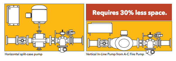
1580 Series vertical in-line fire pumps | AC Fire Pump
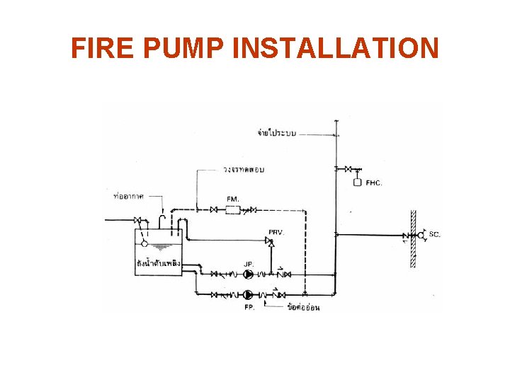
Fire Water Pump Station Design, Piping ... - Cad Crowd Fire Water Pump Station Design, Piping Instrumentation Diagram (P&ID), Flow diagrams and Hydraulic Calculations 2,863 views 28 comments (0 reviews) Sesinando Tibule
Installation and Operation Instructions
PDF The Jockey Pump, an Important Part of a Fire Pump System. The Jockey Pump, an Important Part of a Fire Pump System. August 1, 2009 Rev. No. 2 A Jockey Pump is an important component of a fire pump system. The Jockey ... Choosing a PMP for an interior piping system, supplied by a fire pump system taking suction directly from a water supply without any underground, is a very
![nfpa 20 presentation - [PDF Document]](https://static.fdocuments.in/img/1200x630/reader025/reader/2021042921/54514918af795915308b465e/r-1.jpg?t=1.1.9)
nfpa 20 presentation - [PDF Document]
Typical Configuration of Pump in Piping and ... Typical Configuration of Pump on PID. Figure above reprsents typical piping and instrumentation diagram of pump. Pump should have: Pump Symbol. Make sure you use proper pump symbol. As for example above, I use centrifugal pump. Check your P&ID legend. All the nozzles should be correctly represented with size and flanges.

Jockey Pump Sizing | Prosafe-HSE-Safety Engineering
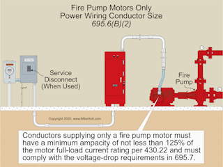
PDF INSTALLATION AND OPERATION INSTRUCTIONS Jockey Pump ... Firetrol Jockey Pump Controllers are listed by Underwriters' Laboratories, Inc., in accor- ... piping procedure of the sensing line between the pumping system and the controller. ... consult the appropriate field connection diagram included with the manual. For proper wire sizing, refer to the National Electrical Code, NFPA 70.

Electric Jockey Pump with Diesel Fire Pump System (PEDJ 50Hz ...
PDF Patterson Pump Company STANDARD JOCKEY PUMP CONTROLLER NEMA TYPE 3R ENCLOSURE A TYPICAL STANDARD JOCKEY PUMP CONTROLLER ELECTRICAL SCHEMATIC PS1 L2A/N 0.33 - 2 240/1/60 (1) #14 AWG (1) [2 MM SQ.] HAND OF F AUT O Patterson Jockey Pump Control Panel Model No. Voltage H.P. Rating Serial No. Encl. Type FLA. A SUBSIDIARY OF THE GORMANN-RUPP COMPANY MADE in U.S.A. 12.01
RESPONSE QUICK
PDF User's Manual - Pump Manufacturing Lag pump stops after the lag stop pressure is achieved and the flow rate is lower than the flow start setting for the off-delay time period. When all lag pumps are stopped, the jockey pump will restart and if the pressure is still being maintained, the pump will shut down after the off -time delay.
ME 444 ENGINEERING PIPING SYSTEM DESIGN CHAPTER 9
PDF QUICK RESPONSE Fire Pumps - Sensing Lines.doc - pdfMachine ... D = Jockey Pump Controller C D A B January 2009 From Supply To System F E FIRE PUMPS ΠSENSING LINES Most commonly the pump controller is connected to the fire protection system by means of piping know as a sensing or pilot line. Each pump, including the jockey pump, shall have its own individual

tpmcsteel on Twitter: "A vivid diagram of fire fighting ...
Fire Pumps Mains.pdf - Geared Project Engineering Pty Ltd TANK & PUMPSET PIPING &. INSTRUMENTATION DIAGRAM. NOT TO SCALE. EXISTING 400kL ... NEW DIESEL & ELECTRIC FIRE PUMPSETS WITH JOCKEY.1 page

PDJ Series Fire Fighting Set With Diesel Pump And Jockey Pump ...
PDF OPERATION & MAINTENANCE MANUAL for VERTICAL TURBINE FIRE PUMPS All pumps are shop serviced and ready for operation when delivered, but there are occasions when considerable time elapses between the delivery date and the time the pump is put into operation. Equipment, which is not in service, should be kept in a clean, dry area. If equipment is to be stored for long periods of time (six months or
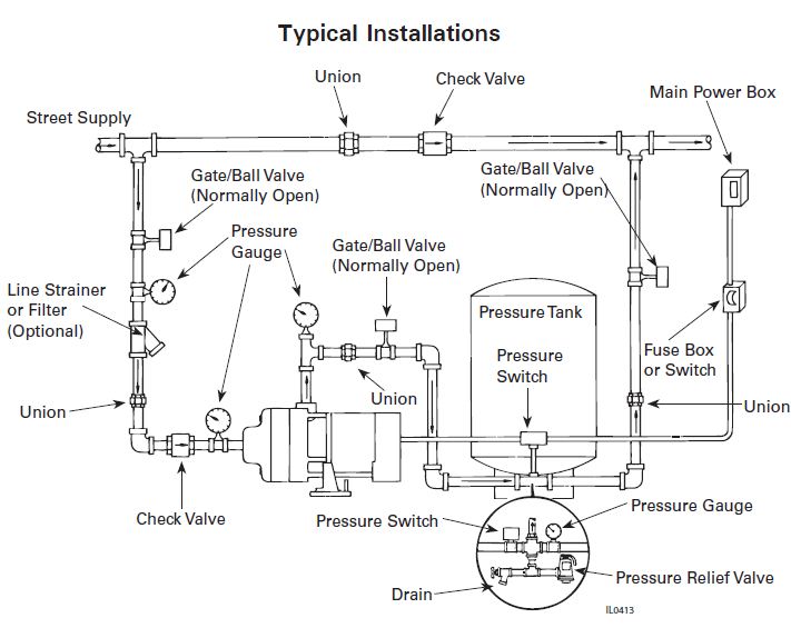
Flint and Walling Typical Piping Diagrams
DRAWING HL-26019, "JOCKEY PUMP SYSTEM P & ID AND ... 5 Oct 1998 — PIPING HIGH POINT VENTS AND LOW POINT ... JOCKEY PUMPS OPERATE ON EMERGENCY AC POWER. ... PROCESS FLOW DIAGRAM FOR THE.1 page
Pumps
Installing Sensing Lines in Jockey and Fire Pump Systems The first part is understanding that the jockey pump and the fire pump need to be located on the high-pressure side of the fire pump piping. Generally, the layout will be the pump suction or inlet, the pump discharge or outlet, and then you must pipe onto the fire pump discharge piping a ¾ "casing relief valve.

Fire Fighting - Pump Room with fire pump , Jockey Pump and Diesel Pump installation Details in hindi
PDF General Information Typical Pressure Sensing Line ... between the pump discharge flange and the discharge control valve, as appropriate. A.10.5.2.1 Installation of the pressure-sensing line between the discharge check valve and the control valve is necessary to facilitate isolation of the jockey pump controller (and sensing line) for maintenance without having to drain the entire system (See figure

Fire pumps sensing line - Fire Protection Specialists
PDF PJPC Jockey Pump Controller - Peerless Pump Figure A-10-5.2.1(a) Piping connection for each automatic pressure switch (for fire pump and jockey pumps). If water is clean, ground-face unions with non-corrosive diaphragms drilled for 3/32-in. orifices can be used in
Installation and Operation Instructions
PDF Fire Pump Package Pumping Systems - Xylem Inc. 2.4.3 Refer to fire pump panel and jockey pump panel wiring diagrams for additional switch/alarm connections. 2.5 MISCELLANEOUS CONNECTIONS 2.5.1 Certain items are shipped loose and are intended to be field installed. Items that may be shipped loose are: hose header and valves, muffler, 10ft fuel tank vent pipe, ball drip valve. If applicable
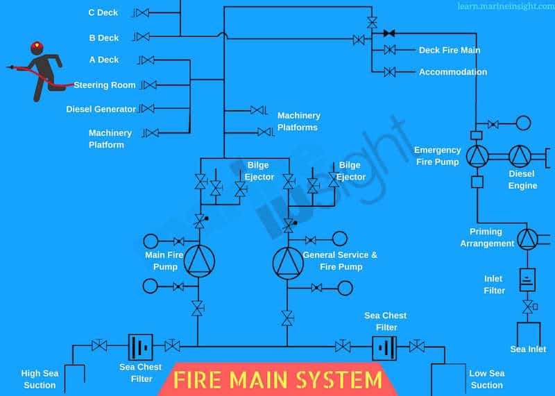
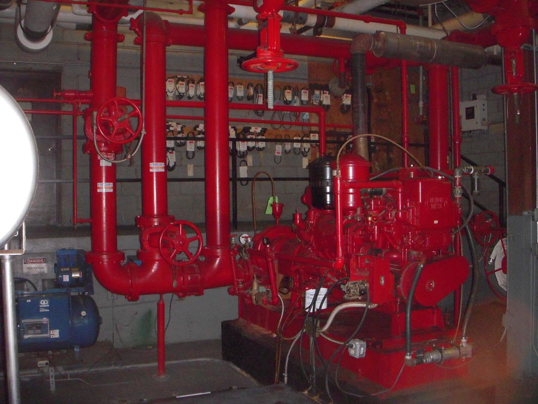
A Guide to Fire Pumps on Ship

Fire pumps sensing line - Fire Protection Specialists

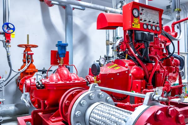
Fire Pump Room
Aurora Packaged Fire Pump Systems - Fox Valley Fire & Safety

Fw pump basis nfpa

Pressure sensing Line in a Fire Fighting Pump Room-Malayalam

ANVIL FIRE - Pump Sizing App

Fire pump settings - NFPA 20 - Fire Protection Specialists
Apresentação do PowerPoint

Examples of Proper Fire Pump Equipment Installations | Steven ...
Fire Pump Systems | EC&M
A-C Fire Pump - Xylem Applied Water Systems - United States
Time is Money and Peerless Pump can save you both
CDL Jockey pump,jockey pump price - ZJBetter
Corcoran Fire Pumps | Fire Sprinkler Service Company in ...

Pin on Meal plan
design of a building fire pump system with integrated parallel ...

FIRE ALARM CHECK VALVE AND FIRE PUMP CONTROLLER SENSING LINE ...

UL Fire Pump | Fire fighting pumps, Pumps, Fire systems
NFPA 20: Changes to the fire pump standard: Regardless of ...

Piping and instrumentation Diagram | Chemical Engineering Portal
MTH Pumps - Fire System Jockey Pumps

Fire Water Pump Station Design, Piping Instrumentation ...
Instruction Bulletin Jockey Pump Controller
0 Response to "40 jockey pump piping diagram"
Post a Comment