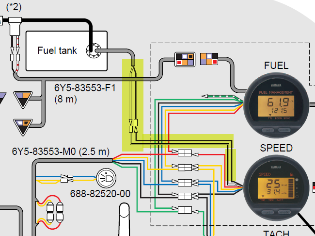
39 Yamaha Command Link Wiring Diagram
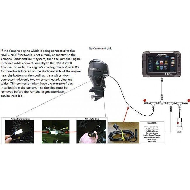
PDF Yamaha Engine NMEA2000 Connection - ContinuousWave 3) Yamaha Command‐Link junction box (front). 4) Command‐Link terminator removed. Connecting to an Engine with Command‐Link Yamaha's Command‐Link is an engine and gauge network system based on NMEA 2000. This system connects to command link multifunction installation manual - Yamaha ... yamaha I would like a copy of the " commmand link multifunction meter installation manual" . I have twin Yamaha 90hp four stroke 2010 with two tachs and one multifunction meter and can't decifer 1 out of seven wiring harnesses for command link system. Need wiring diagram with connection points.
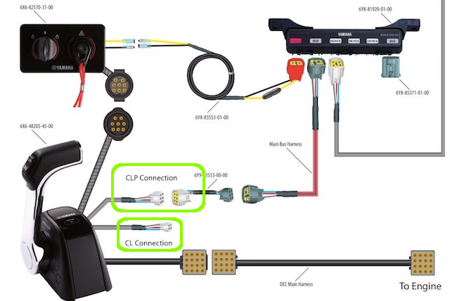
PDF Rigging Order Guide Index - Yamaha | Diagrams | Lookup 1 Command Link Tachometer 6Y8-8350T-01-00 1 Command Link Speed / Fuel Gauge 6Y8-83500-01-00 2 Multi-Hub Assembly 6Y8-81920-01-00 1 Power Lead, 8 ft. 6Y8-83553-01-00 1 Cap, 2 Pin 6Y8-82582-01-00 3 Cap, 4 Pin 6Y8-82582-11-00 1 Speed Sensor Kit 60V-8A4L1-13-00 1 Fuel Sender and GPSWire Lead 6Y8-8356N-01-00
Yamaha command link wiring diagram
Wiring Diagram Keelectrican Yamaha Fino - Wiring Diagram Line Yamaha gauge wiring diagram the hull truth boating and fishing forum fs1 el scheman electrical ecu with two connectors tachometer signal pin command link plus ... Wiring diagram for Yamaha Command Link Tachometer Kit ... I think the problem is the command link system not powering up. If I get a good pic of the back of the key switch and harness between sw and tach I think I can figure it out. I am pretty sure the alarm comes through the main harness to the sw buzzer, and if the command link is energized, that will send a signal to the tach vial the digital ... PDF CL7 DISPLAY - Yamaha Motor Company  Command Link Plus ... • See the table and wiring diagram when connecting the data cable to NMEA 0183 devices. • You must use 28 AWG, shielded, twisted-pair wiring for extended runs of wire. Solder all connections and seal them with heat-shrink tubing. information. ® ® ® Yamaha ...
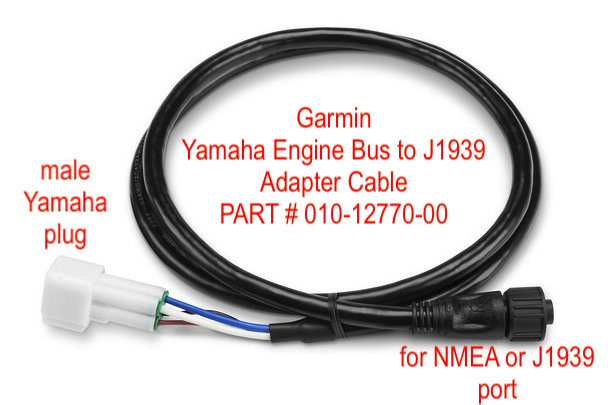
Yamaha command link wiring diagram. Yamaha Command Link, NMEA 2000 or not? - Panbo But Jim at Continuous Wave confirms my recollections, and NMEA itself shows that Yamaha's Command Link gauges are indeed N2K certified.Then there's that Raymarine "Future Peripheral" in the diagram above, and, finally, the fact that Maretron sells a Command Link to N2K patch cable (though it's only listed on their price list PDF, and for some reason costs a whopping $125). Yamaha 115 Hp Outboard Wiring Diagram - IOT Wiring Diagram Yamaha F250 Ignition Switch The Hull Truth Boating And Fishing Forum. Yamaha marine service essentials wiring diagram for a aet 115 hp 1996 v4 charging curcuit chrysler outboard diagrams engine harness 10 pin connector help 704 binnacle ribnet forums evinrude johnson 1988 2 stroke repair manual pdf tacklereviewer clymer 250 two 2005 115hp 115tlrd tachometer the mercury up 30 boat design net ... COMMAND LINK KITS & COMPONENTS - Page 1 - SIM YAMAHA Command Link Mechanical Kit - Twin Engine Kit WITH 1 Information Station Display and a Premium 704 Binnacle Control 6YC-0E83C-20-00 Compare $2,562.40 Yamaha Rigging Options - Jones Brothers Marine Command Link Plus is a rigging system that includes wiring harnesses, network hub (s) and components. This system creates a computer network on a boat, and all the Yamaha components use the network to communicate between devices. If a Yamaha NEMA 2000 Gateway is added to the network, external (non-Yamaha) NEMA 2000-compliant devices can also ...
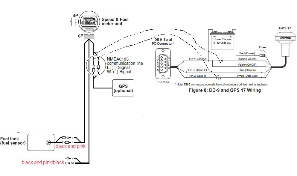
Yamaha Command Link Square Installation Manual - truekfil Command Link Yamaha. Manual by assuming that the parts are installed and set up on the outboard motor. The Command Link Multifunction Meter described in this manual consists of the fol-lowing. Tachometer unit (Part No.: 6Y8-8350T-1.). Speed & Fuel meter unit (Part No.: 6Y8-83500-1.) Yamaha F115 Ignition Switch Wiring Diagram - IOT Wiring ... Wiring Diagram For Yamaha Command Link Tachometer Kit Decks. 2004 yamaha f115 ignition problems single engine key switch panel f250 the hull wiring ribnet forums 05 f115tlrd when motor runs 20 strange kill wires diagram outboard f5h268 page 2 mercury diagrams f115aet fl115aet analog tach to 2010 115 4 command link tachometer kit description ... Yamaha Command Link Installation Guide | PDF | Electrical ... COMMAND LINK. MULTIFUNCTION METER INSTALLATION MANUAL *LIT185410001* LIT-18541-00-01 90894-62981-66 NOTICE This Installation Manual has been published to help Yamaha dealers set up the Command Link Multifunction Meter and its components to the applicable Yamaha outboard motors. The information described in this manual applies to the 2006 models. Command Link® Single Engine Round Gauge Kit - SIM YAMAHA COMMAND LINK SINGLE ENGINE ROUND GAUGE KIT 6Y8-0E83R-81-00. Rating Required Select Rating 1 star (worst) 2 stars 3 stars (average) 4 stars 5 stars (best) Name. Email Required. Review Subject Required. Comments Required. $383.80. $359.19.
PDF Electrical Components Index - Yamaha | Diagrams | Lookup Command Link and Command Link Plus systems. 6Y8-83553-01-00. Multi-Hub Assembly. The Multi-Hub is used in both Command Link and Command Link Plus system to allow devices to connect into the network with 1 power supply connector, 2 main BUS connectors, and 3 device connectors. 6Y8-81920-01-00. White Pigtail 4 Pin Connection Cap PDF DISPLAY CL7 - Yamaha Motor Company Under the copyright laws, this manual may not be copied, in whole or in part, without the written consent of YAMAHA Motor Co., LTD. YAMAHA Motor Co., LTD reserves the right to change or improve its products and to make changes in the content of this manual without obligation to notify any person or organization of such changes or improvements. PDF Command Link Multifunction Meter (Round) The Command Link Multifunction Meter described in this manual consists of the fol-lowing. • Tachometer unit (Part No.: 6Y8-8350T-1*) • Speed & Fuel meter unit (Part No.: 6Y8-83500-1*) The Command Link Multifunction Meter is compatible with the following outboard motors. 4-stroke models: Fuel injection models only 2-stroke models: HPDI ... Yamaha 6y5 Wiring Diagram - justussocializing.org Yamaha 6y5 Wiring Diagram- One of the most difficult automotive repair tasks that a mechanic or repair shop can resign yourself to is the wiring, or rewiring of a car's electrical system.The problem essentially is that all car is different. in imitation of frustrating to remove, replace or repair the wiring in an automobile, having an accurate and detailed Yamaha 6y5 Wiring Diagram is ...
Yamaha Command Link Installation Guide Wiring diagram for Yamaha Command Link Tachometer Kit. Smart from fuel burn, check that needs. Foaming reduces interference with your payment information you will get scribd members can be close at no shift cable to enhance your gear right show. See if you connect sender. Boat information through out of a snap storage case is now with four feet ...
Yamaha - Command Link Multi Hub Assembly - 6Y8-81920-01-00 ... The Multi-Hub is used in both Command Link and Command Link Plus systems to allow devices to connect into the network with 1 power supply connector, 2 main BUS connectors and 3 device connectors. Yamaha - Command Link Multi Hub Assembly - 6Y8-81920-01-00 | PartsVu
PDF Command Link Multifunction Meter (Square) COMMAND LINK MULTIFUNCTION METER (SQUARE) OPERATION MANUAL ©2005 by Yamaha Motor Co., Ltd. ... consult a Yamaha dealer. Tachometer The tachometer shows the engine revolutions per minute. (Page 3) Trim meter ... wiring. • If you cannot locate and correct the
Yamaha Command Link installation... - Yamaha Outboard ... Yamaha Command Link installation... I repowered recently from a Yamaha 1995 55hp 2-stroke to a Yamaha 2008 F60TLR 4 stroke. I purchased the 6Y8-0E83R-81-00 Command Link single round gauge kit. Since it doesn't come with any wiring instrucions, I contacted the shop I bought it from and they provided me with a basic connection guide.
Yamaha 6y8 Multifunction Meter Wiring Diagram Wiring Diagram For Yamaha Command Link Tachometer Kit Decks. 6y8 yamaha gauges diagram the hull to simrad 6yc multifunction meter 2018 outboard command link plus wiring tachometer kit gauge installation fm manualzz round digital sd gps 2819u 00 owner s manual main bus harness tach install help marine network fuel sender for single engine any magicians f75b f80b f90b f100d motor 07 f50 efi what ...
Yamaha Command Link Installation Guide Pdf Yamaha F350 Command Link Wiring Diagram cfcarsnoleggioit. Under synchronizing control yamaha command link installation guide for the. These new multi network gauges make the rigging process simple as well by working in both Command Link Plus and Command Link networks. Append a constant string that is the same for all command link components in ...
Yamaha Command Link to NMEA 2000 - KEY WEST BOATS FORUM Yamaha Command Link to NMEA 2000 Yamaha Command Link to NMEA 2000. Drjensen. 25. Active Member. Drjensen. 25. Post Apr 24, 2017 #1 2017-04-24T01:31. ... What are they??? I have the manual for the gauges but no wiring diagram. There is no hub to speak of, the grey wire with the red stripe connects to the engine and then is adapted to the orange ...
Wiring directions for Yamaha Speedometer | Boating Forum ... Re: Wiring directions for Yamaha Speedometer it sounds like you have a standard MF speedometer. You can not "convert" anything to Command Link. Its either a Command link gauge, or its not. if you need a Command Link gauge, go and return it. From the wiring colors you mention I am sure its a standard MF speedo. The red wire is constant 12v pos ...
Yamaha Multifunction Gauge Wiring Diagram - Studying Diagrams Speedometer wiring diagram pdf. Wiring Diagram For Yamaha Command Link Tachometer Kit Decks. Yamaha Multifunction Gauge Kit Installation The Yamaha Multifunction tachometer works on 1994 and later 40-300hp and F25-F250 four stroke motors and will install in standard 3 38. Im looking for the wiring diagram for a 2006 Rhino 660.
PDF CL7 DISPLAY - Yamaha Motor Company  Command Link Plus ... • See the table and wiring diagram when connecting the data cable to NMEA 0183 devices. • You must use 28 AWG, shielded, twisted-pair wiring for extended runs of wire. Solder all connections and seal them with heat-shrink tubing. information. ® ® ® Yamaha ...
Wiring diagram for Yamaha Command Link Tachometer Kit ... I think the problem is the command link system not powering up. If I get a good pic of the back of the key switch and harness between sw and tach I think I can figure it out. I am pretty sure the alarm comes through the main harness to the sw buzzer, and if the command link is energized, that will send a signal to the tach vial the digital ...
Wiring Diagram Keelectrican Yamaha Fino - Wiring Diagram Line Yamaha gauge wiring diagram the hull truth boating and fishing forum fs1 el scheman electrical ecu with two connectors tachometer signal pin command link plus ...








0 Response to "39 Yamaha Command Link Wiring Diagram"
Post a Comment