39 Push Button Horn Wiring Diagram
Horn button wiring | Team Chevelle Hey all, planning on installing a horn in my '72 Elco this weekend (original horn/wiring was removed by PO) and have some questions.. The back of the steering wheel button (pic attatched) has one male connector where it looks like one wire may have ran up to it thru the largest hole next the nut at the end of the steering column, is this correct? Air Horn Wiring Diagram - Wirings Diagram Air Horn Wiring Diagram - air horn wiring diagram, air horn wiring diagram compressor, air horn wiring diagram switch, Every electric structure is composed of various unique pieces. Each component should be set and linked to other parts in particular manner. Otherwise, the structure will not work as it should be.
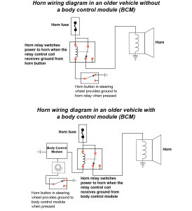
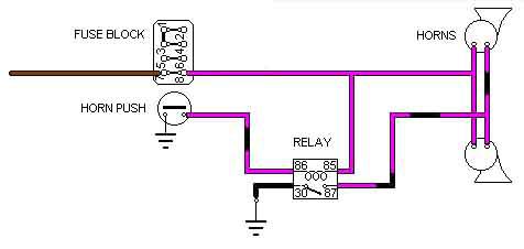
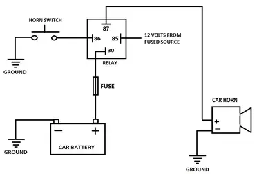
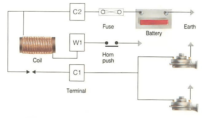
Horn Diagram Please - Hot Rod Forum When you push the horn, it depresses the element, and provides ground to the relay, which in turn closes the relay. This activates power to the horns. The horn power wire in this diagram is GREEN. This runs from the horns, and back to the normally open contact of the relay. The Center wiper (CW) contact on the relay, Is wired to the power wire.
Push button horn wiring diagram
Push button Horn Wiring Diagram - autocardesign push button horn wiring diagram electrick wiring diagram co. Architectural wiring diagrams operate the approximate locations and interconnections of receptacles, lighting, and steadfast electrical facilities in a building. Interconnecting wire routes may be shown approximately, where particular receptacles or fixtures must be upon a common circuit. 1-Way System) 2-Way Paging System REMOTE START SYSTEM WIRING Low Current 12 Pin Plug YELLOW: (-) HORN CHIRP HONK OUTPUT (Programmable 15, 20 or 40 milliseconds) Connect to the LOW CURRENT Negative Horn Trigger wire usually located near the steering column. If the vehicle horn circuit requires 12V, then a relay is required. RELAY WIRING: Connect the Yellow wire to terminal #85, connect relay Horns & Wiring Diagram - YouTube Horns & Wiring DiagramAmazon Printed Bookshttps:// Kindle Editionhttp:// ...
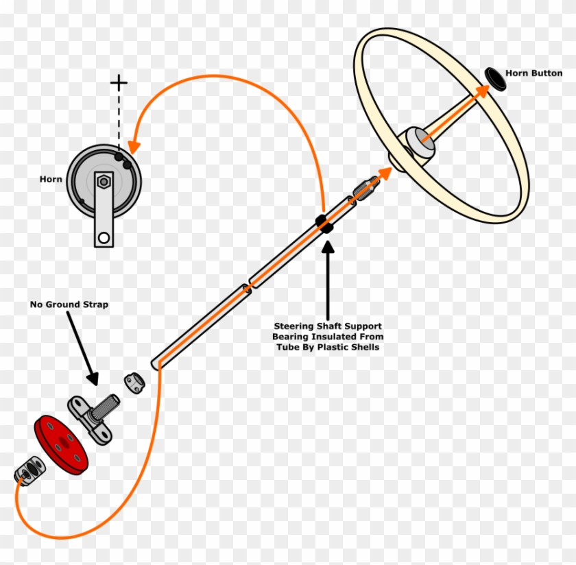
Push button horn wiring diagram. How to Wire a Boat Horn - Our Pastimes Slide the black wire underneath and tighten it down. Run a section of red wire from the horn to the switch, then to the battery and cut to length. Strip 3/8 inches of insulation off both ends of the wire. Connect the red wire to the positive wire at the horn with a butt connector. Loosen the two terminals on the switch with a screwdriver. Horn Button Installation...wiring the Fast Clear Easy Way ... I searched youtube and found an easy way to hook up the horn button however the guy was showing wiring which made it complicated, I had to keep rewinding his... Horn Push - mgb-stuff.org.uk Horn Push. North American Mk1, and up to and including 1969 (other markets): The brush rubs on a brass cylinder (slip-ring) attached to the column, but insulated from it. A wire comes from the slip-ring up through the centre of the column to a ball-shaped end ('bullet' below). This presses on a brass contact attached to the middle of the horn push. How to Install a Universal Horn Button | It Still Runs The single wire button will require only one wire connection, which will be a hot (positive) wire to the fuse block or to original horn wire in the horn wiring loom. The single wire button requires that you mount the button directly into the metal of the dashboard frame or some other metal source.
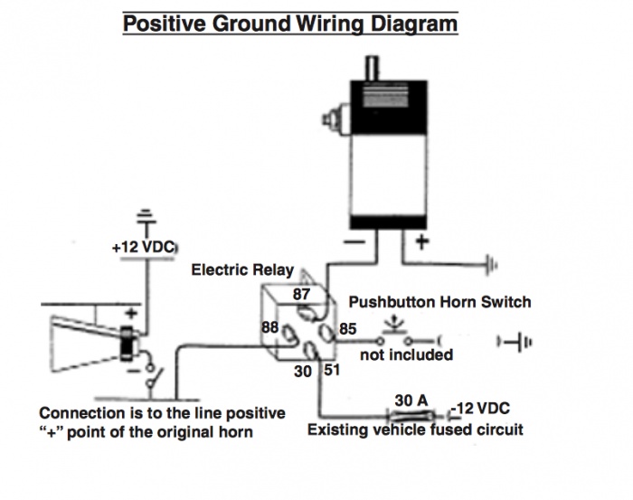
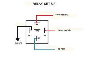
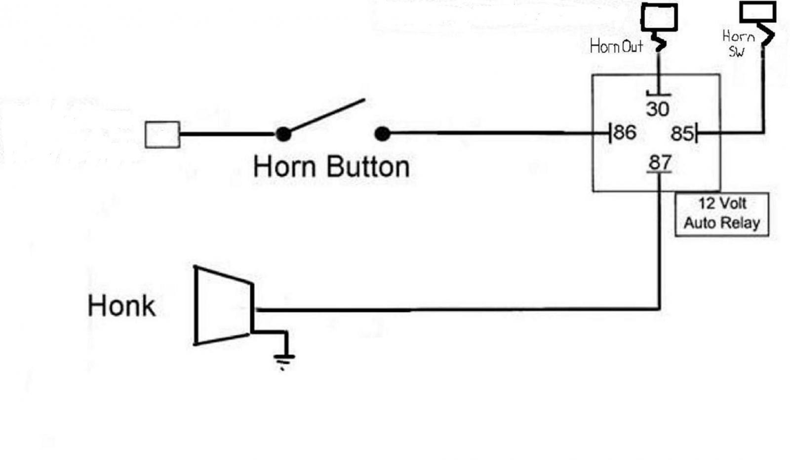
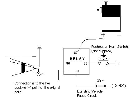
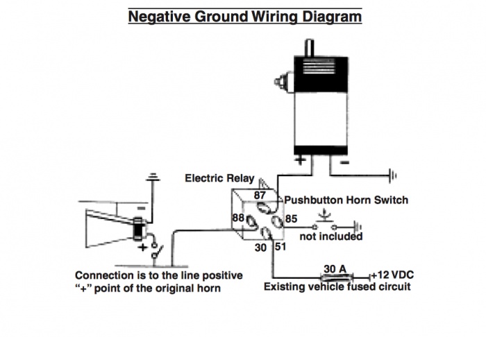
Great Wiring Diagram For Horn Relay HORN RELAY Simple ... Guys .. my defender originally came with the original bullbar with spots attached . they use to work when I trigger brights via the steering stalk. the lighting system was poor so I added the headlight relay wiring harness and couple months ago removed bumper and spots. deceided recently to install a new set of spots...now they don't switch on. the spots has a seperate 4 pin relay ..I checked ... diagram 41 push button horn wiring diagram. A diagram which summarizes the four imperatives expressed in being artisa… Written By Demetrius Gleichner November 22, 2021 Add Comment Edit. Written By Demetrius Gleichner Wednesday, November 17, 2021 Add Comment Edit. Home. Subscribe to: Posts (Atom) PDF How to Wire a Horn Button Using a Relay horn will only honk ... HOW TO WIRE A HORN BUTTON USING A RELAY 12 GAUGE 12 GAUGE 20 AMP FUSE . AUTOMOTIVE Homvs PUSH BUTTON - HORN BUTTON GROUND SOLENOID VALVE ON HORN 87A GROUND . Author: Gary Wright Created Date: 5/26/2016 8:36:40 AM ... SOLVED: How to wire a push button horn? 2002 Lancer ... Options. Permalink. History. You need to wire in a relay. The switch will not carry the current needed. Run positive from the switch to terminal 85 on the relay. Ground the switch to the body near the switch. Run a wire from terminal 86 to ground (negative). Run battery power into terminal 87 on the relay and run from terminal 30 to the horn.
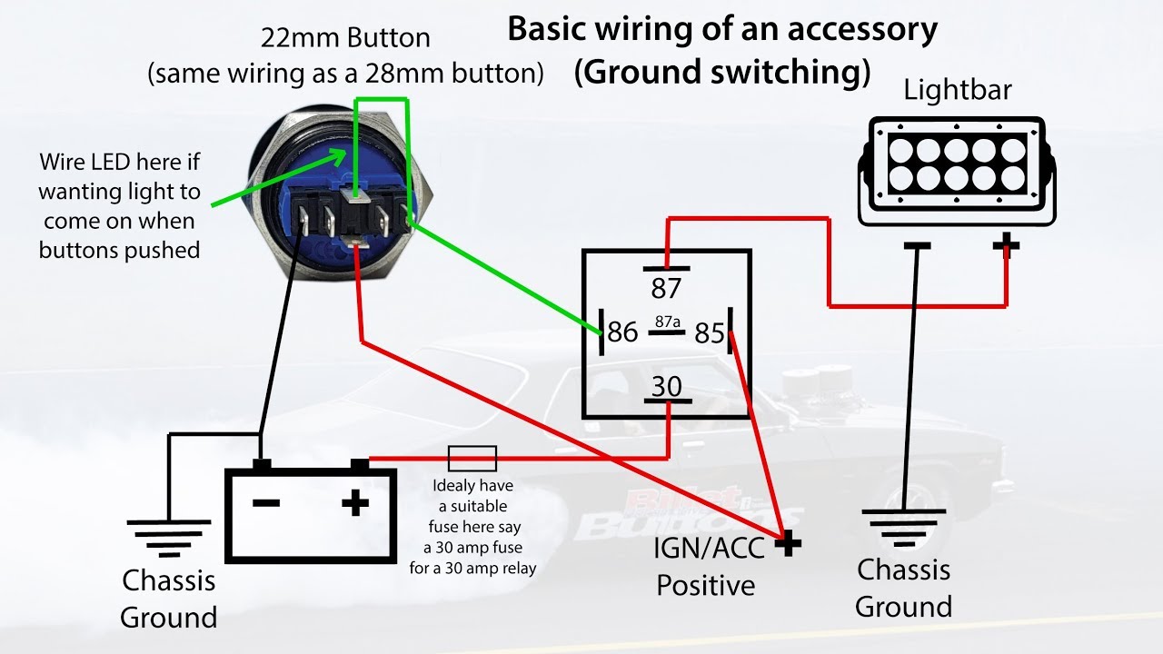
Wiring diagram - Custom Billet Buttons RGB LED button are polarity sensitive. The 19, 22 and 25mm buttons with an RGB Led have a Common Anode. That means they share a common Positive (+12vdc) lead and you must ground each color pin you want to light. The wire color on the pigtail will match the buttons LED color pin. You can use them for a single color or make your combination of color. PDF ST280 - LCS770 PLITSTR311 REV D - Galls Auxiliary Input Function - The auxiliary input (green wire) allows activation by an external source of either the Horn or the Manual push -button functions. This input is usually wired into the vehicle horn switch. The wiring diagram on page 8 shows two connection examples. NOTE: Permanent disconnection of the vehicle horn is NOT recommended. PDF A Simple Way to Improve the Mgb'S Horn Circuit The horn proved to be fine, though, checked by applying an earth lead directly to the terminals. Further checks with a multi-meter ensured that the circuit as such was OK, i.e. pushing the horn button provided earth. So why didn't the horn sound? A closer look at the MGB's wiring diagram revealed that no relay was provided, which means HOME - Car PDF Manual, Wiring Diagram & Fault Codes DTC 2015-01-12 · horn wiring diagram for Toyota auris 2008 model #359. Liz (Wednesday, 20 October 2021 02:55) I need a great wall steed Ute 2018 service log book and manual please #358. Carla McClinton (Friday, 15 October 2021 15:34) I need manual for 1993 Panoz roadster #357. Bongani (Thursday, 14 October 2021 09:25) Hi.. I need Zafira B 1.8 Enjoy 2007 codes …
Horn doesn't work — Ricks Free Auto Repair Advice Ricks Free ...
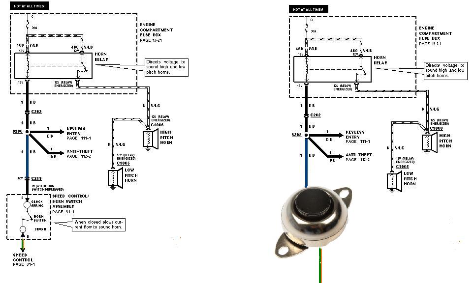
1971 F100 Horn wiring!? - The FORDification.com Forums FYI, that diagram is WRONG on some parts of the horn wiring... It shows the Horn button wire going to the instrument lights and the instrument lights to the horn signal wire. Here is what I'm talking about; This is how it is now and it is WRONG!!! No way - No how does the horn wire come from the light switch or the horn button go to the ...
Need help! Horn from Harbor Freight I have no idea how to ...
Amazon.com: ESUPPORT 12V Car Auto Blue LED Light Momentary ... WOWLED Laser Horn Rocker Switch, Waterproof Train Horn Wiring Kit, LED Illuminated Backlit + Relay Wiring Harness Kit for Truck Car Boat SUV ATV UTE 4X4 On/Off Toggle Switch Twidec/16MM Raised Speaker Horn Momentary Push Button Switch 5/8" Mounting Hole 12V Blue Led Light Black Stainless Steel Shell 1NO 1NC SPDT with Pre-wiring Wires Switch For ...
SOLVED: How to wire a push button horn? 2002 Lancer ...
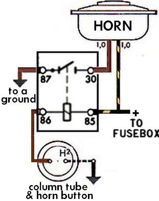
Technical - Need some help wiring a horn button | The H.A.M.B. When the button is pushed, it establishes a ground, completing the circuit to the coil (electromagnet). When energized, the horn contact is made and it blows. If you've ever seen a crashed car whose horn blows continuously, likely the isolated 12v wire in the column got damaged and grounded out. Hope this helps.

55.2-59 Horn Wiring - WTH? - The 1947 - Present Chevrolet ...
Horn Buttons | O'Reilly Auto Parts Part #: 5899. Line: GNT. Horn Buttons. Select a store to see pricing & availability. Search for a store page input 6. When autocomplete results are available use up and down arrows to review and enter to select. Touch device users, explore by touch or with swipe gestures.
TheSamba.com :: Beetle - 1958-1967 - View topic - Horn Wiring
How to wire a horn to a button instead of using the horn ... Is it possible to connect the horn wire to a simple button? Does the horn work by grounding the circuit to make the horn sound? I have tried to find a wiring diagram for this circuit, but have been unsuccessful. VOLVO-V70 September 24, 2016, 3:02am #2. I looked at your profile and apparently you have had this vehicle since 2008 or longer. ...

14-'18) - 2015 - Trying to install a secondary push button ...
PDF ST160 - SS750 - Galls Auxiliary Input Function - The auxiliary input (green wire) allows activation by an external source of either the Horn or the Manual push -button functions. This input is usually wired into the vehicle horn switch. The wiring diagram on page 5 shows two connection examples. NOTE: Permanent disconnection of the vehicle horn is NOT recommended.

install a horn button Questions & Answers (with Pictures) - Fixya
small boat electrical horn wiring help | Boating Forum ... 34,933. Mar 31, 2016. #2. The horn should have one side going to ground. The other side should go from a fuse/breaker to the horn button/switch and to the other side of the horn. Start at the horn button and see if you have 12V on one side and that 12V goes to the other side when pressed.

Horn Problem - Morris Minor Owners Club
Push Button Starter Switch Wiring Diagram - Wirings Diagram Push Button Starter Switch Wiring Diagram - push button ignition switch wiring diagram, push button start switch wiring diagram, push button starter switch wiring diagram, Every electrical arrangement consists of various distinct parts. Each component ought to be placed and linked to other parts in specific manner. Otherwise, the arrangement won't work as it ought to be.
Horn Circuit Question | GM Truck Club Forum
How to Shut Off a Jammed Horn: 10 Steps (with ... - wikiHow 2019-12-23 · Push the horn several times. ... The fuse box cover or the manual should have a diagram that tells you which fuse is part of the horn's wiring. Turn off the ignition, then pry the fuse out by hand or with fuse pullers. If you do not have your car manual, search online for your make and model, followed by "manual" or "fuse diagram." The fuse box is usually located …
wiring a horn relay 77 mgb : MGB & GT Forum : MG Experience ...
PDF 800-2.0 Typical Wiring Diagrams for Push Button Control ... Typical Wiring Diagrams For Push Button Control Stations 3 Genera/ Information @ Each circuit is illustrated with a control circuit (continued) schematic or line diagram and a control station wiring diagram. l The schematic or line diagram includes all the components of the control circuit and indicates their
Can you help? Which is the horn power wire? - Kawasaki Forums
switches - 5 pin push button switch with LED AC wiring ... \$\begingroup\$ Thanks Jim but what you linked is for a DC application and a 6 pin switch. I have my wiring diagram above. the push button switch can handle 250v/5a. What I'm trying to figure out is, if I wire this into an AC wall lamp as the switch, how should I wire in the LED part of the switch, which is presumably DC) to achieve what I discussed in my questions?(ie.

Passing Light Using Horn switch Diagram I Busina at ilaw sabay Gagana
APIELE 16mm 12V Momentary Speaker Horn Push Button Toggle ... Twidec/19MM Raised Speaker Horn Momentary Push Button Switch 3/4" Mounting Hole 12V Blue Led Light Silver Stainless Steel Shell 1NO 1NC SPDT with Pre-Wiring Wires Switch for Car Modification G19LB-BU 4.4 out of 5 stars 524
TheSamba.com :: Beetle - Late Model/Super - 1968-up - View ...
PEUGEOT Fault Codes DTC - Car PDF Manual, Wiring Diagram ... 2017-01-07 · horn wiring diagram for Toyota auris 2008 model #359. Liz (Wednesday, 20 October 2021 02:55) I need a great wall steed Ute 2018 service log book and manual please #358. Carla McClinton (Friday, 15 October 2021 15:34) I need manual for 1993 Panoz roadster #357. Bongani (Thursday, 14 October 2021 09:25) Hi.. I need Zafira B 1.8 Enjoy 2007 codes …
Need help wiring an air horn with a Relay - The Hull Truth ...
Ooga Horn Relay Wiring Diagram Package Includes: Ooga Horn, Mounting Hardware, 12V Relay, Horn Button, Installation wire kit with fuse and installation Instructions. Ships from our West. wire is coming from the horn button on the steering wheel to the relay, trying to find why the horn does not work, relay, fuse ok, but can't find a wiring diagram.
Horn Wiring Diagram Wiring Diagram Air Horn Wiring - 1963 Vw ...
PDF Helix Chrome Trim & Accessories Installation Manual switch and then push the crank button on the column. This diagram shows the difference between the wires (that come out of the column wire hole) for the column operation and the wires for the push button start operation. See the following pages for the correct wiring of the push button functionality. RA1000 3 RAS12 3 SW20 1 Operation & Features

Amazon.com: Twidec/16MM Raised Speaker Horn Momentary Push ...
Horns & Wiring Diagram - YouTube Horns & Wiring DiagramAmazon Printed Bookshttps:// Kindle Editionhttp:// ...

Car Horn Wiring Diagram || Single Terminal Horn Wiring || Single Pole Horn
1-Way System) 2-Way Paging System REMOTE START SYSTEM WIRING Low Current 12 Pin Plug YELLOW: (-) HORN CHIRP HONK OUTPUT (Programmable 15, 20 or 40 milliseconds) Connect to the LOW CURRENT Negative Horn Trigger wire usually located near the steering column. If the vehicle horn circuit requires 12V, then a relay is required. RELAY WIRING: Connect the Yellow wire to terminal #85, connect relay
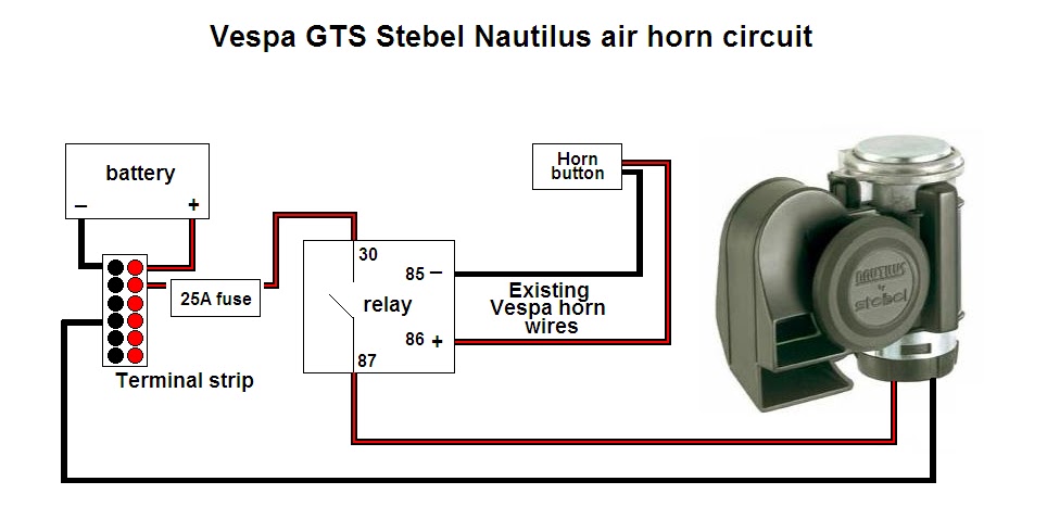
Stebel horn fitting on a 2010 Speed Triple | Triumph Rat ...
Push button Horn Wiring Diagram - autocardesign push button horn wiring diagram electrick wiring diagram co. Architectural wiring diagrams operate the approximate locations and interconnections of receptacles, lighting, and steadfast electrical facilities in a building. Interconnecting wire routes may be shown approximately, where particular receptacles or fixtures must be upon a common circuit.
CAR HORN-HOW TO FIX-TEST-REPLACE-ADJUST AND MORE -

Motorcycle Horn Relay Diagram and Wolo Wiring Diagrams ...
19mm 22mm Billet Automotive Buttons Wiring Diagram Video RGB Controller
Technical - Need some help wiring a horn button | The H.A.M.B.

Clip Buttons Wire - Vw Beetle Horn Wiring Diagram 1969 - Png ...

Air Horn Wiring Diagram Switch Dual Relay 12v Car Nitro Boat ...
Horn Options Lighted vs Non-Lighted Switch Install | Kawasaki ...
Starter Kill - Passive with Horn Output and Horn Interrupt ...

Horn Wiring | Car horn, Horns, Electrical diagram

Horn Rocker Switch | Carling Contura II | Illuminated | Accessory
busted clockspring - F150online Forums
Horn wiring help needed | Triumph Rat Motorcycle Forums
Car horn not working? | How a Car Works

Upgrading Your Stock Motorcycle Horn: A Quick Primer
how to wire 12 volt oooga horn | Hot Rod Forum

Upgrading Your Stock Motorcycle Horn: A Quick Primer
Air Horn Relay
12V Universal Horn Wiring Harness Relay Kit Installation ...

Train horn relay switch
Need help! Horn from Harbor Freight I have no idea how to ...
BAD BOY™
0 Response to "39 Push Button Horn Wiring Diagram"
Post a Comment