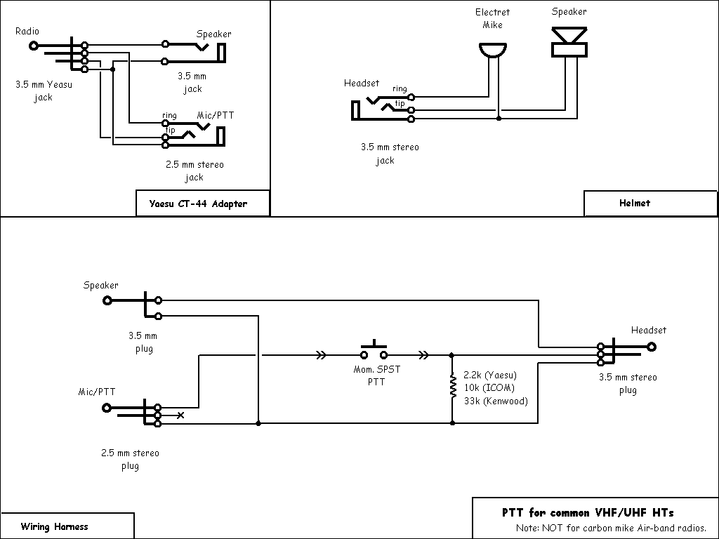
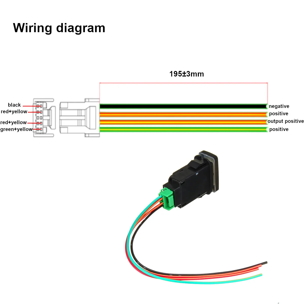
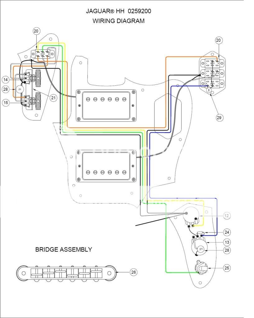
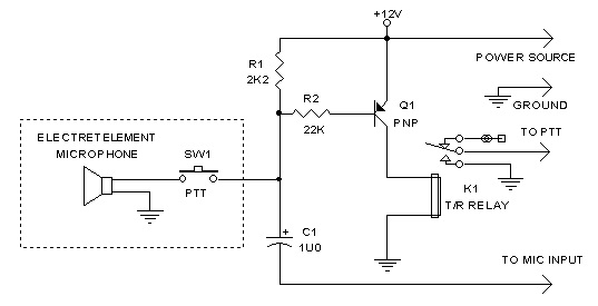
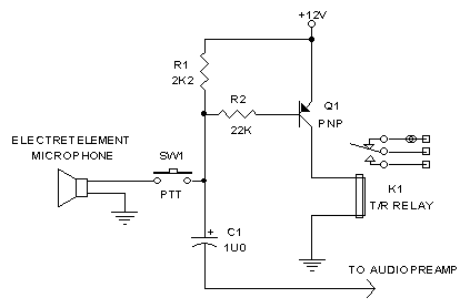
42 push to talk switch wiring diagram
PTT refers to "push-to-talk or press-to-talk". When an operator pushes the button on a hand held microphone or "walkie talkie" as shown below, the transceiver ... 01-25-2009, 08:18 AM. Jerry Carter. Join Date: May 2005. Location: Montrose, CO. Posts: 127. Push to talk wiring. Almost done with wiring, but I need a little help on wiring the push to talk switches. My Stark-supplied harness has two bundled wires of six wires each coming from the PMA9000X audio panel for the headphone and mic jacks.
Push to Talk Switch Wiring Diagram – wiring diagram is a simplified suitable pictorial representation of an electrical circuit. It shows the components of the circuit as simplified shapes, and the capacity and signal associates along with the devices.
Push to talk switch wiring diagram
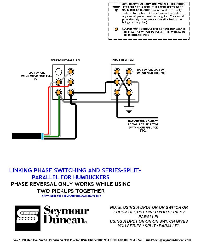
Product FAQ · Wiring Diagrams · Installation & Dimensions. Orders & Info. There are a billion wiring diagrams for 4 and 5 wire pickups, and most don't really explain the . Pulling up on the push pull will split the pickup. Well, here we'll talk about how to wire a humbucker pickup so that it can be split into a single coil pickup using a push ... David Clark Isocom Wiring Diagram. Interconnect Wiring Diagram (PTT ICS & VOX Version) the output power of current Sigtronics SPA or David Clark Isocom systems. David Clark ISOCOM Intercom (Unit Only) P/N: G, , 6h 35m . Telex PT Push To Talk Switch for aircraft w/o wired-in intercom PTT, Connect the jacks with the proper wire and according to ... Positive pressure on diaphragm produces positive voltage on pin 1 (red wire) with respect to pin 2 (black wire). Switch. Built-in, leaf-type, non-locking, Push-to-Talk. Shock Mount. Internal rubber vibration isolator. Cable. Highly durable cable with effective hum shielding, four conductors (two-shielded), plastic jacketed
Push to talk switch wiring diagram. No soldering, wiring or tools required for installation. ... Push-To-Talk Switches, including the David Clark Company Incorporated Model C10-15,.2 pages Wanted to install a PTT switch on the co-pilot yoke. I see the wire (on the pilot side) goes from the microphone jack connection to the PTT switch and then to the intercom DB-9 connector. So I assumed pushing (closing) the PTT switch causes the intercom to channel the audio from the mike to the appropriate radio. 30 Oct 2019 — In a 3.5mm, you have 3 or 4 wires depending on the plug. For example, this one has wires for both a mic and a headphone: ...2 answers · Top answer: A Normally Closed Momentary Switch (NKK) - Very cheap and tiny, on Amazon: XLX 50pcs Red ... The function of a Push-To-Talk Switch (“PTTS”) is to place the aircraft radio ... (or use the existing hand-microphone jack and wire in a headset jack).2 pages
Emergency Push button Wiring Diagram Download. Assortment of emergency push button wiring diagram. A wiring diagram is a simplified standard photographic depiction of an electrical circuit. It shows the elements of the circuit as streamlined forms, and the power as well as signal connections between the gadgets. A wiring diagram generally gives info regarding the loved… wiring the push-to-talk functions to the aircraft. ... if the aircraft already has a push-to-talk switch hard wired to the mike input jack, it must be disconnected [Filename: perm4way.pdf] - Read File Online - Report Abuse I'm replacing a standard light switch with a smart one. The wiring diagram confuses me. Neutral goes to N, and to the plant which is presumably earth, and to L1? I'm completely flummoxed. I'd have thought Neutral to N, permanent live L, switched live L1, earth to? Anywhere? Anywhere here's the diagram, appreciate any help. [https://imgur.com/a/bsSvfpb](https://imgur.com/a/bsSvfpb) FWIW, the earth(s) are not currently fixed to the back of the metal junction box. 1. The Telex PT-300 push-to-talk switch will enhance your current radio system and increase safety. This lightweight, compact black switch attaches directly to the yoke for hands-free communications. Simply use your thumb to flip the Telex switch and enjoy perfect radio transmission. Hands-free intercom use is no longer a luxury with the PT-300.
1 Nov 2020 — Your PTT button most likely is just a SPST momentary switch, so it has two wires that are connected when the button is depressed. One wire goes ... top case, normally used for trim, and one switch in the bottom case, normally the push to talk (PTT). It may look like there is one long switch in the center of the top case, but there are actually two switches, mounted end to end (these are switches #1 and #3 in the drawings). The single pole double throw switches in the G205 stick grip are ... Sigtronics Ptt Switch Intercom Use with headset and a portable intercom. Cannot use with headset alone. Quick Shop. ... Reliable and easy to use push-to-talk has a rubber non-slip grip and robust velcro strap. Ive used them in our previous Cub and again in the most recent Cub. Hey everyone, I have tried to search around for this on Google but haven't found it. I picked up some new Mojotone 500k push-push pots for a cheap guitar that I received as a present and dropped it off to my guitar guy to wire up. I tried to describe what I was after and the old guy gave me a little guff about it and said he'd need a diagram. So here I am. I have 2 volume pots and 1 tone pot. I would like to have each volume pot be able to be muted with the push. The tone pot I was thinking ei...
Hi, I've got a 1950's motor that i would like to wire to a push button on/off switch. Is the a push button switch on the market to do what i want in the diagram or a way of wiring one as i can not find any on ebay? The only ones i can find that is a close match is the 3 phase switches like this one (ebay No. 290930766073).
Aircraft Spruce is a worldwide distributor of certified and homebuilt aircraft supplies.
Talking on the communication radio in your homebuilt aircraft requires a simple push-to-talk (PTT) switch—an electrical push-button switch of the momentary-contact type. This switch is often mounted on the grip of the control stick for convenience so that a press of a finger gets you on the air.
on a material list to fabricate a PTT switch assembly. for a Icom A-22 hand held. I have the headset adapter, but I need to make a PTT for a top of stick. mount. Purchased a over the counter unit, disassembled. and has four wire contact at the switch and what I am assuming a 1/8 inch jack plug.
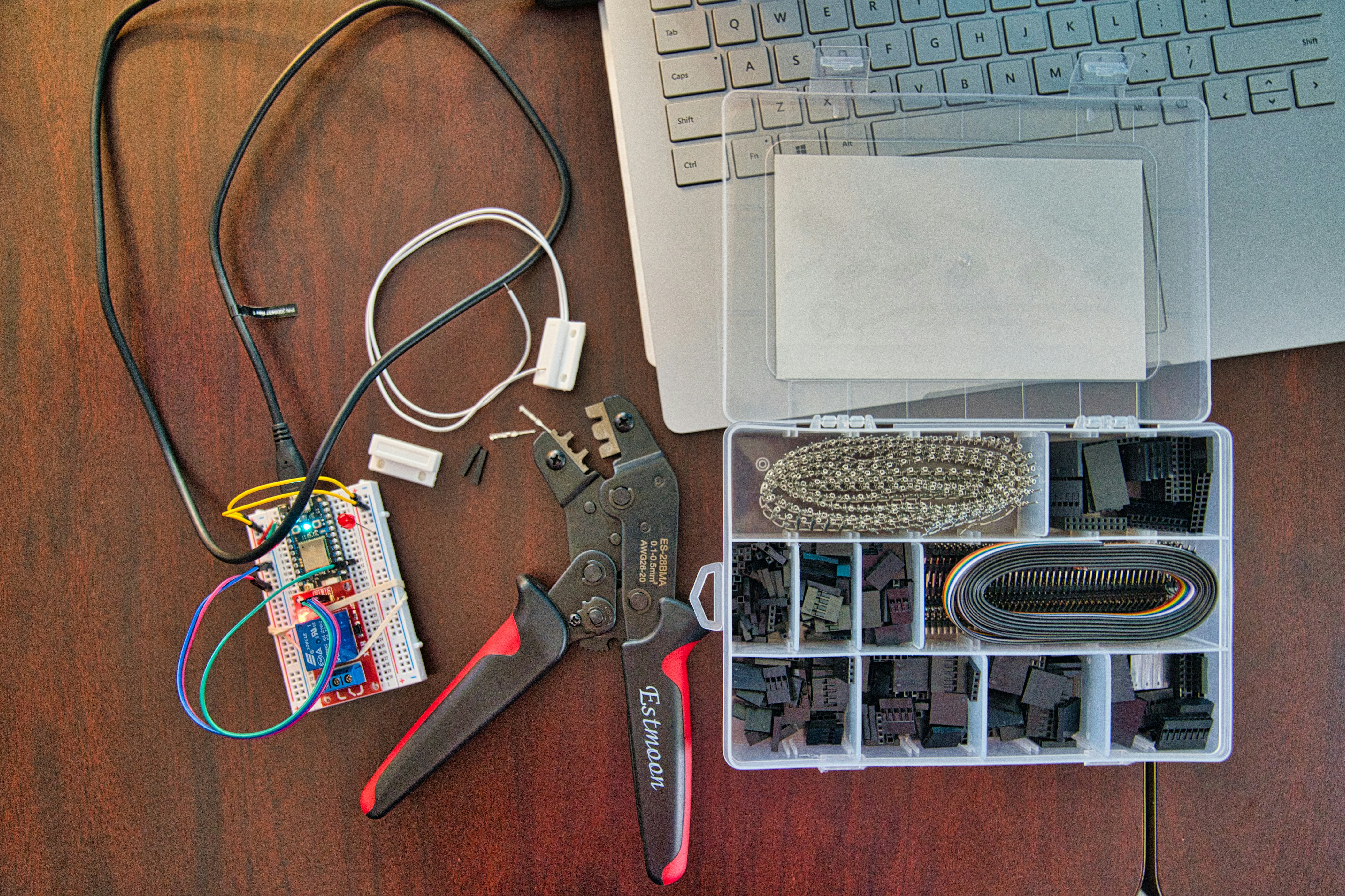
A wire crimper, particle IOT device, magnetic reed switch, laptop, and jumper wires at the start of an internet of things connected project
I have a push-to-talk (PTT) button permanently installed on my left yoke that works fine. It's the only PTT switch in my aircraft. I hooked up an in-line portable PTT switch on the right yoke, but it doesn't work correctly. I tried a second one with the same result, so I'm thinking it must be the way the aircraft interphone sockets are wired on the aircraft.
I have some ditch lights that I installed that I'd like to come on with the high beams as well as a switch that I installed. I know how to do the wiring on that side, but what I'm not sure is which wire I need to tap into (I'll try to connect the wire into the harness, rather than literally tapping the wire) for the high beam signal. ​ I am thinking that my easiest option to accomplish this is from the wires that come from the multifunction switch. I have searched for any indicatio...
Connect the loop of the bare wire in a hook shape to both box and the switch. Now, connect the loop of the black wire to the terminal at the bottom of the switch. Connect the white wire in a hook shape at the top of the switch's terminal. Insert the configuration inside the box, tight the screw, and again turn ON the light to check.
WIRING INSTRUCTIONS Connections should be made as shown in Figure 4 and indicated in Table 1 *A. White / red (pilot push-to-talk) must correspond with white / black (pilot mic input) as shown. *B. The blue wire from Pin 3 must be connected to the aircraft radio headphone output- NOT the speaker output.
Collection of push to talk switch wiring diagram. A wiring diagram is a streamlined standard photographic depiction of an electrical circuit. It reveals the elements of the circuit as simplified shapes, as well as the power as well as signal links in between the tools.
This switch controls one single outlet (which shows 20V when the switch is off - phantom voltage? safe for a power strip + computer to be plugged into?). The (plastic) box has FOUR different NM cables (I think I'm using the right terminology) - 3 are white/black/bare and one is white/black/red/bare. The switch was mounted upside-down, which I understood once I saw the sheer amount of wires shoved behind it. Pics below but I think the lovely MSPaint wiring diagram makes it easier to see what's...

If you like my photos vote on me in the Morocco Web Awards instagram section in here: https://vote.marocwebawards.com/instagram/themastersphotography-699
The first aircraft radios used carbon-granule microphones almost identical to microphones used on telephones. However, a second function was needed on the microphone in the form of a push-button to key the transmitter and effect a changeover from receive to talk . . . hence the name push-to-talk or PTT switch.
over the radio. An instructor can talk to a student pilot over the intercom, while the student is transmitting over the radio w ithout the instructor's voice also being broadcast. Music will never be transmitted. If your push-to-talk switch fails, you can use an existing handhel d mic to talk on the radio while listening over the intercom. 2 ALL
Jun 12, 2020 · push to talk switch wiring diagram – What is a Wiring Diagram? A wiring diagram is a straightforward visual representation with the physical connections and physical layout of the electrical system or circuit. It shows how a electrical wires are interconnected and will also show where fixtures and components may be attached to the system.
Telex Pt-300 Push-To-Talk Switch Attaches to any control wheel. Simple installation, no tools required. Simply wrap hook and pile strap around control wheel.
THIS IS MY MOST VIEWED VIDEO!!! Use my Amazon links to buy whatever you need!!WE HIT 1000 SUBS!!! NOW LIKE THE VIDEO HAHAHAWe go step by step in wiring up a ...
18.02.2017 · To find out if this is the case with your rig, get a 12-volt test light, push the switch to Storage, then disconnect the negative terminal on one of the batteries. Touch the probe to the post and the alligator clip to the cable. If the light comes on, you have a draw. Safe travels, David Solberg. Related: RV Battery Basics: A Beginner’s Guide
May 28, 2021 · Push to talk switch wiring diagram collections of wiring diagram ptt switch wire center. Pin out pin 1 mic pin 2 ptt pin 3 nc pin 4 nc pin 5 nc pin 6 5vdc pin 7 gnd pin 8 gnd. What you will have is a further engaged target market and the go with the go with the flow of information is clean and quick our site is updated every day with new powerpoint templates.
Multiple Light Wiring Diagram. This diagram illustrates wiring for one switch to control 2 or more lights. The source is at SW1 and 2-conductor cable runs from there to the fixtures. The hot and neutral terminals on each fixture are spliced with a pigtail to the circuit wires which then continue on to the next light.
10.11.2021 · Here are the steps you need to take to wire the ignition switch yourself. However, depending on the vehicle in question, you might need a push-button starter switch wiring diagram. Step 1: Park the Vehicle. Ensure that your vehicle is parked on level ground before turning off the engine. Step 2: Ascertain the Terminals on the Ignition Switch
I only see a phase switch if it has a mini toggle on the seymour duncan site
Feb 28, 2018 · Push to Talk Switch Wiring Diagram Collection. August 9, 2018. February 28, 2018 by headcontrolsystem. push to talk switch wiring diagram – A Novice s Overview of Circuit Diagrams. A first consider a circuit layout may be confusing, yet if you can check out a metro map, you can check out schematics. The objective coincides: obtaining from factor A to direct B. Literally, a circuit is the path that enables electrical energy to circulation.
Full disclosure - I have no business trying to wire anything up. :) I feel like this should be easily found but I’ve watched too many YouTube videos and google searches and still cannot understand how to wire up my switch correctly. I have a two button NO / NC - start / stop pushbutton box. It has standard 110 coming into the box via a pigtail plug. On the other side I have a fan with hot neutral and ground. If I wire the NO switch into the system by passing the hot through the button then t...
Car Harness and Push-To-Talk (PTT) switch To helmet kit Nexus TP-120 Nexus TJ -101 socket, or equivalent Connector for Motorola radio Female mini-XLR socket, looking into connector e.g. Switchcraft TA3F Push -to -talk switch (PTT) Radio ground Ear + Mic + Ear - Mic - Radio ground PTT This diagram shows the layout of a typical race
Hey all, would appreciate any advice, even rudimentary diagrams if anyone can spare the time. I'm trying to wire up a Fender wide-range humbucker with a volume pot, and a push/pull pot which in the down position would act as a regular tone knob, but in the up position act as a 'spin-a-split' mod, blending between single-coil and full use of the humbucker's double coils. I understand how to wire up a humbucker in the standard way, and how to do the spin-a-split \*\*in place\*\* of the tone knob, ...
Common Wiring diagrams. wiring diagram for QEL panics mag lock wiring diagrams. chexit wiring diagram. lever locks for fire doors. emergency release tool. two single doors with panic bars. two single doors with panic bars. push button release electric strike. - WIRING INSTRUCTIONS— magnetic lock or fail safe strike with button, keypad and PIR ...
Typical Wiring Diagrams For Push Button Control Stations 3 Genera/ Information @ Each circuit is illustrated with a control circuit (continued) schematic or line diagram and a control station wiring diagram. l The schematic or line diagram includes all the components of the control circuit and indicates their function.
Positive pressure on diaphragm produces positive voltage on pin 1 (red wire) with respect to pin 2 (black wire). Switch. Built-in, leaf-type, non-locking, Push-to-Talk. Shock Mount. Internal rubber vibration isolator. Cable. Highly durable cable with effective hum shielding, four conductors (two-shielded), plastic jacketed
David Clark Isocom Wiring Diagram. Interconnect Wiring Diagram (PTT ICS & VOX Version) the output power of current Sigtronics SPA or David Clark Isocom systems. David Clark ISOCOM Intercom (Unit Only) P/N: G, , 6h 35m . Telex PT Push To Talk Switch for aircraft w/o wired-in intercom PTT, Connect the jacks with the proper wire and according to ...
Product FAQ · Wiring Diagrams · Installation & Dimensions. Orders & Info. There are a billion wiring diagrams for 4 and 5 wire pickups, and most don't really explain the . Pulling up on the push pull will split the pickup. Well, here we'll talk about how to wire a humbucker pickup so that it can be split into a single coil pickup using a push ...
![[ZH_9566] Wiring Diagram Ptt Switch Schematic Wiring](https://static-resources.imageservice.cloud/107629/ham-radio-station-grounding-schematic-free-download-wiring-diagram.jpg)










![[ZH_9566] Wiring Diagram Ptt Switch Schematic Wiring](https://static-cdn.imageservice.cloud/175493/push-to-talk-switch-wiring-diagram-wiring-diagram-third-level.jpg)


![[WO_4415] Wiring Diagram Ptt Switch Free Diagram](https://static-cdn.imageservice.cloud/175536/wiring-diagram-ptt-switch-schematic-diagram-download.gif)
![[VS_7738] Wiring Diagram Ptt Switch Free Diagram](https://static-assets.imageservice.cloud/175497/ptt-switch-wiring-diagram.jpg)

0 Response to "42 push to talk switch wiring diagram"
Post a Comment