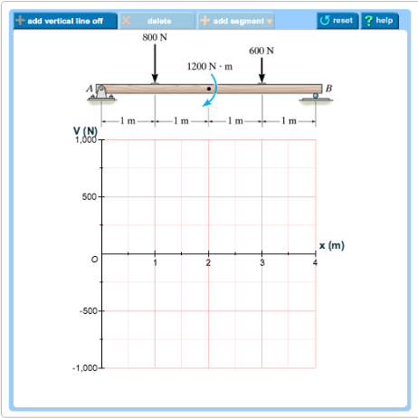
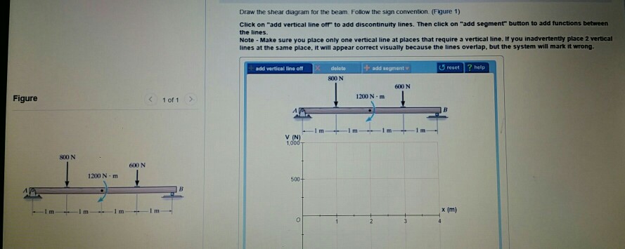
42 7.76 draw the shear diagram for the beam. follow the sign convention. (figure 1)
When solving beam diagrams in class and at home you may check your answers by using this free online beam calculator: SkyCiv Cloud Engineering Software Problem 1: State the maximum shear force and bending moment values. Problem 2: State the maximum shear force and bending moment values. Problem 3: A 24 meters long beam is simply supported at 3 meters from each end. 30.09.2021 · N. Korea's parliamentary session. This photo, released by North Korea's official Korean Central News Agency on Sept. 30, 2021, shows Kim Yo-jong, North Korean leader Kim Jong-un's sister and currently vice department director of the ruling Workers' Party's Central Committee, who was elected as a member of the State Affairs Commission, the country's …
Problem 7.76: For the beam and loading shown, (a) Draw the shear and bending-moment diagrams, (b) Determine the location and magnitude of the maximum absolute value of the bending moment. View Answer. Solve Prob. 7.78 assuming that the 2-kip force applied at E is directed upward.
7.76 draw the shear diagram for the beam. follow the sign convention. (figure 1)
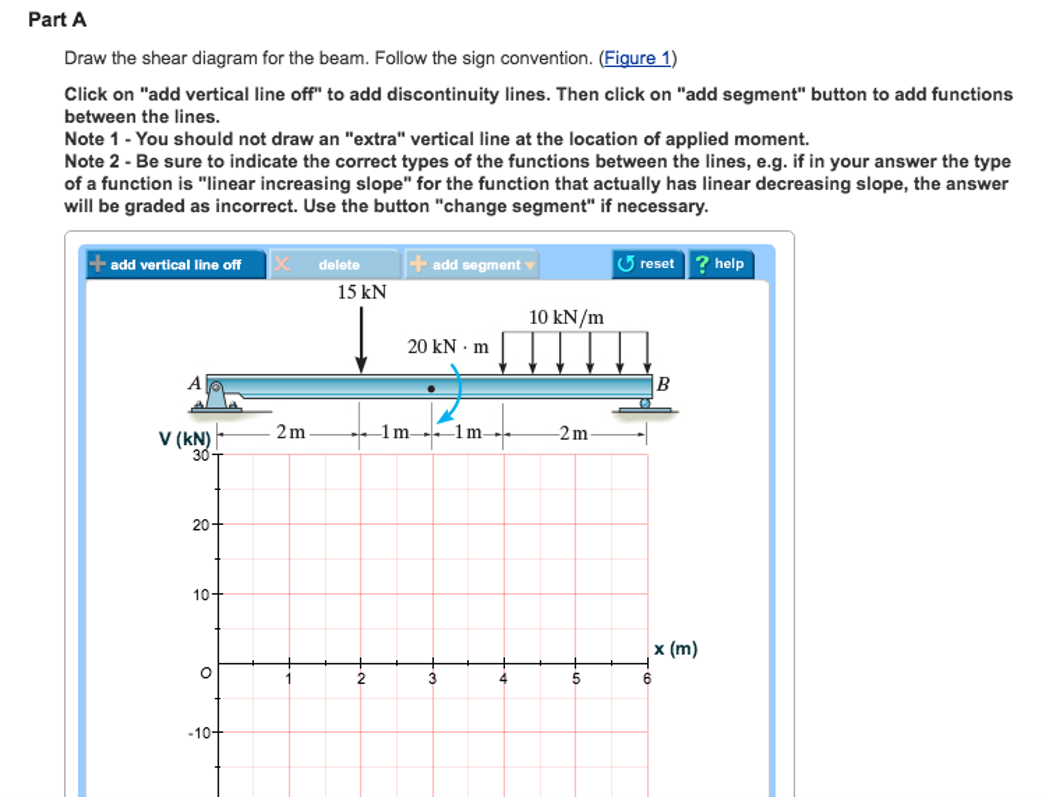
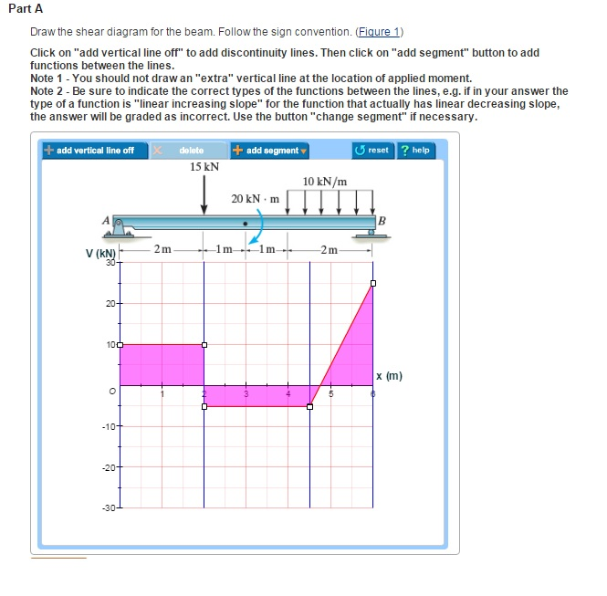
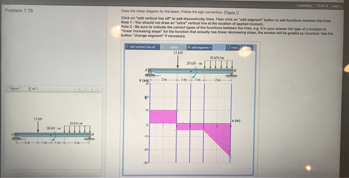
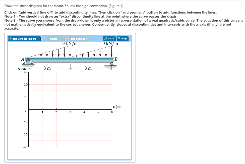
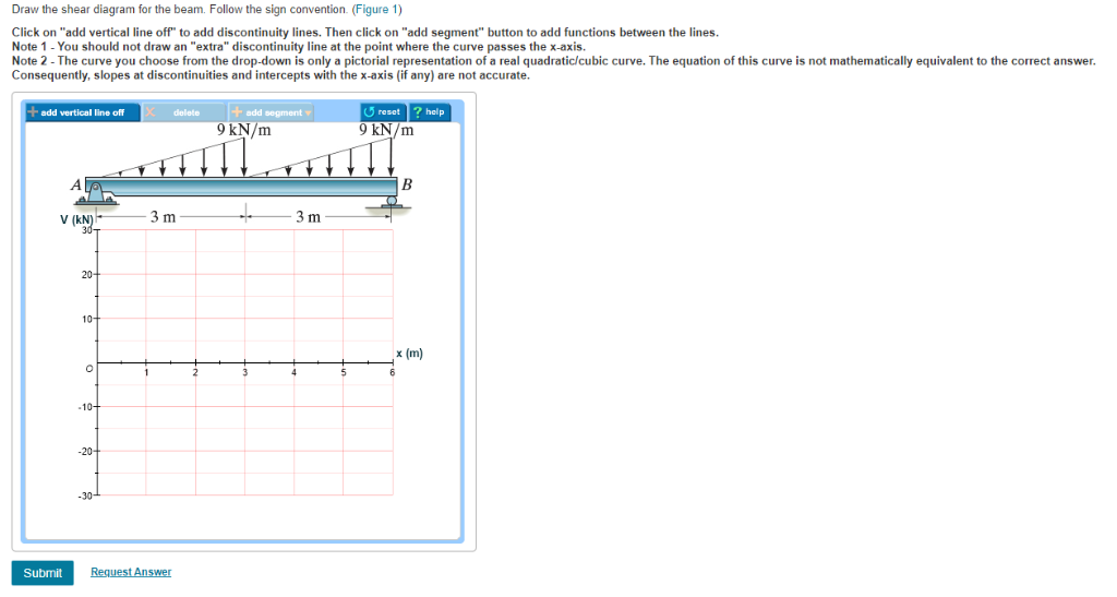
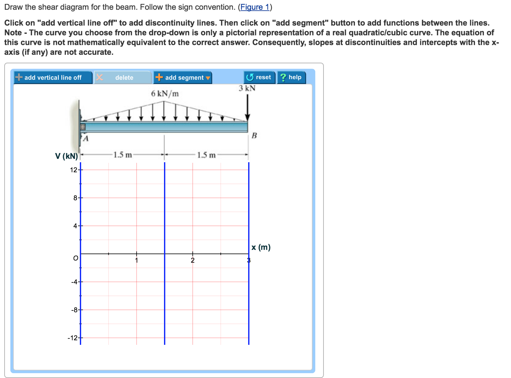
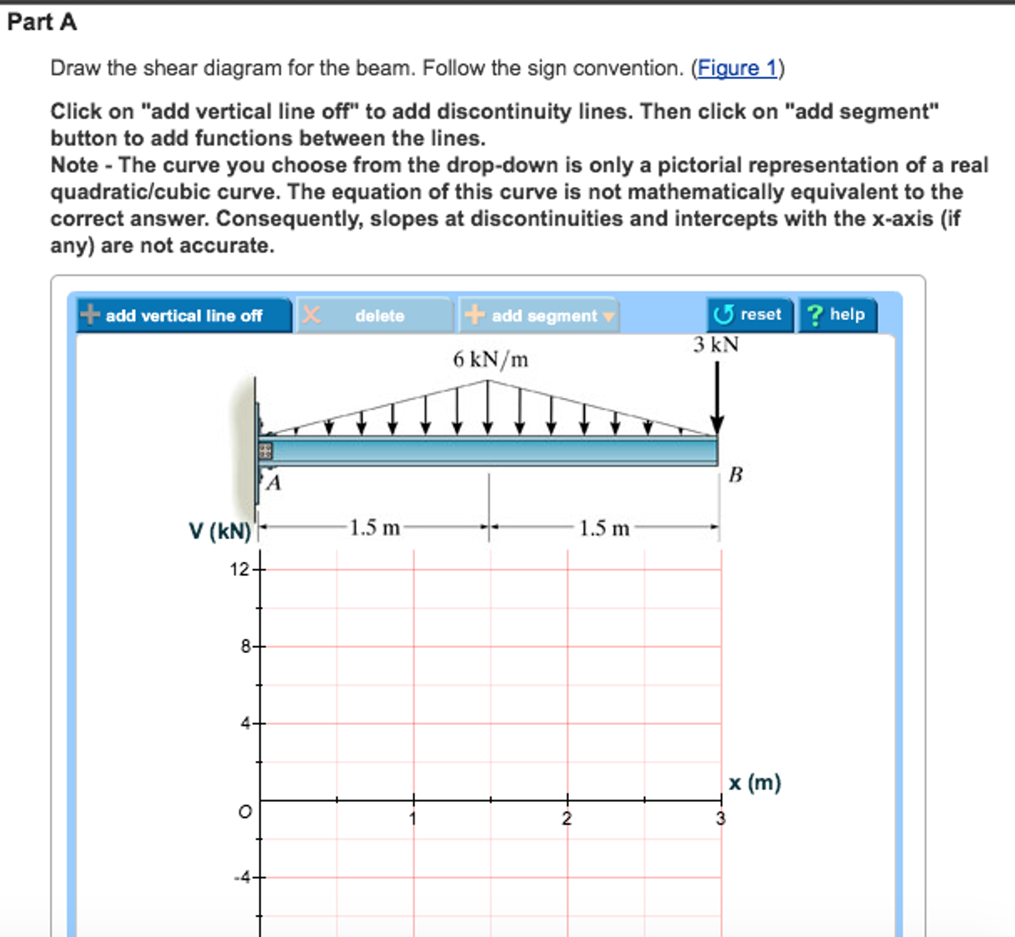
Problem 7.76 4 of 7 Rey Part A Draw the shear diagram for the beam. Follow the sign convention. (Figure 1) Click on "add vertical line off" to add discontinuity lines. Then click on "add segment" button to add functions between the lines. Note 1 - You should not draw an "extra" vertical line at the location of applied moment. Step 2 of 3. (A) Draw the free body diagram of the section of the beam at the range as shown in Figure (3). Here, horizontal location on the beam with respect to point A is x and the maximum magnitude of distributed load at the x location is y. Determine expression for the maximum magnitude of distributed load ( y) using similar triangles rule ... beam from the left hand end and summing up the areas of shear force diagrams using proper sign convention. xThe process of obtaining the moment diagram from the shear force diagram by summation is exactly the same as that for drawing shear force diagram from load diagram.
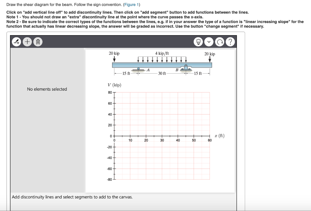
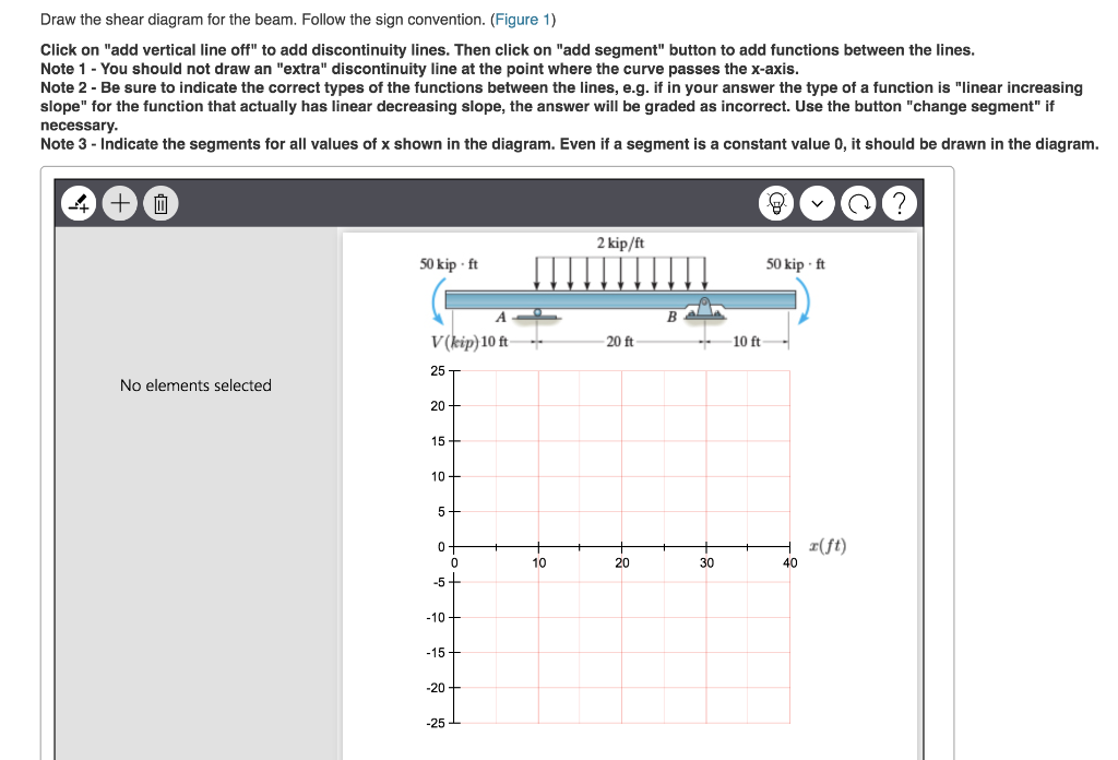
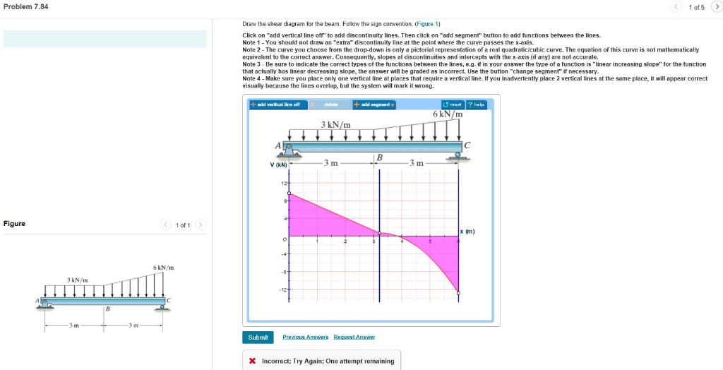
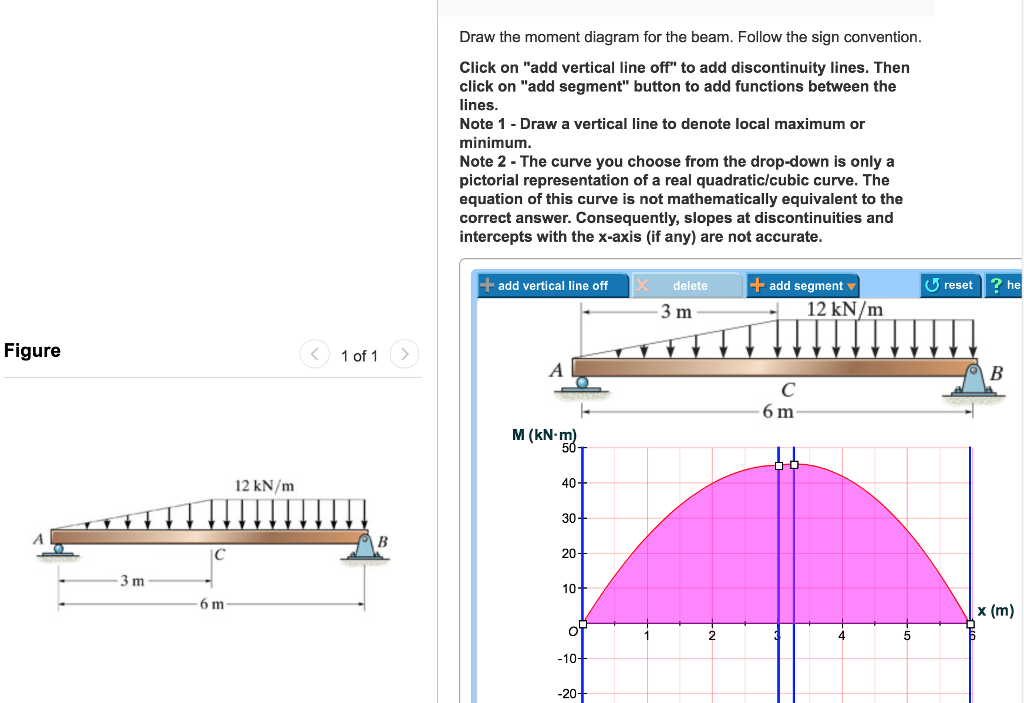
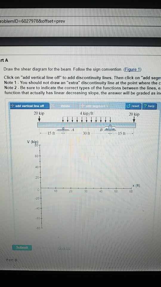
7.76 draw the shear diagram for the beam. follow the sign convention. (figure 1). Transcribed image text: Problem 7.77 Part A Draw the shear diagram for the beam. Follow the sign convention. (Figure 1) Click on "add vertical line off" to add discontinuity lines. Then click on "add segment" button to add functions between the lines Note 1- You should not draw an "extra" discontinuity line at the point where the curve passes the x-axis Note 2 Be sure to indicate the correct ... Question: Draw the shear and moment diagram for the beam.Problem 7-71 from:Engineering Mechanics: Statics, 14th editionRussell C. HibbelerThank you guys for ... The shear diagram of a beam is shown in the figure. Draw the shear diagram for the beam. 6.8.Place the appropriate function between the lines of discontinuity, ensuring the endpoints have the correct values. 1.6 2.4 (kn) 36 16 6. Problem 7.84 Draw the moment diagram for the beam. Follow the sign convention. Click on "add vertical line off" to add discontinuity lines. Then click on "add segment" button to add functions between the lines. Note 1 - Draw a vertical line to denote local maximum or minimum.
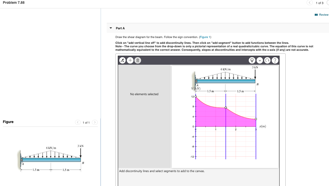
*7—56. Draw the shear and moment diagrams for the cantilevered beam. 300 1b - diagram of the beam's left through an arbitrary shown in fig. b will be to write the and mcnnent quations. The inœnsity the triangldar útributed load at of sectioning is — = 3333r Referring Fig. b , o V = {-300- 1b — +3001-0 The shear and diagrams shown in ... Problem 7.88. Part A. Draw the shear diagram for the beam. Follow the sign convention. (Figure 1) Click on "add vertical line off" to add discontinuity lines. Then click on "add segment" button to add functions between the lines. Note - The curve you choose from the drop-down is only a pictorial representation of a real quadratic/cubic curve. Academia.edu is a platform for academics to share research papers. Problem 7.76 Part A Draw the shear diagram for the beam. Follow the sign convention. (Figure 1) Click on "add vertical line off" to add discontinuity lines. Then click on "add segment" button to add functions between the lines. Note 1 Note 2 - Be sure to indicate the correct types of the functions between the lines, e.g. as incorrect.
1 Answer to Draw the shear force and moment diagrams for the beam The supports at A and B are a thrust bearing and journal bearing, respectively. (Figure 1) Follow the sign convention. 1 Answer to Problem 4.24 Part A Conslder the beam shown in (Fioure 1). Follow the sign Draw the shear diagram for the beam. Click on "add vertical line off" to add discontinuity lines. Then click on "add segment" button to add functions between the lines. Note 1 Bc sure to indicate the correct types of the... Take A Sneak Peak At The Movies Coming Out This Week (8/12) Minneapolis-St. Paul Movie Theaters: A Complete Guide; Best Romantic Christmas Movies to Watch To determine the shearing stress in a connection such as a bolt, pin, or rivet, you first show the forces exerted by the various members it connects. In the case of pin C (Fig. 1.23a), draw Fig. 1.23b to show the 50-kN force exerted by member BC on the pin, and the equal and opposite force exerted by the bracket.
Solved: Draw The Shear Diagram For The Beam. Follow The Si ...
Problem 4.3-1 Calculate the shear force V and bending moment M at a cross section just to the left of the 1600-lb load acting on the simple beam AB shown in the figure. Solution 4.3-1 Simple beam 4 Shear Forces and Bending Moments 259 AB 800 lb 1600 lb 120 in. 30 in. 60 in. 30 in. M A 0: R B 1400lb M B 0: R A 1000lb Free-body diagram of segment ...
Solved: Part A Draw the shear diagram for the beam. Follo
Beam sign convention shear forces and bending moments in lecture 13 equilibrium of beams chapter 9 deflections of beams mechanics e shear moment diagrams. ... Solved Problem Statement The Cantilever Beam Shown In Figure Is 1 Transtutors. ... For The Figure Below Determine Part A Draw Shear Diagram Beam Follow Sign Convention B Moment.
Solved: Problem 7.88 1 Of 3 M Review Part A Draw The Shear ...
Note 1 You should not draw an "extra" discontinuity line at the point where the curve passes the x-axis. Note 2 Be sure to indicate; Question: Problem 7.80 3 of 3 Draw the shear diagram for the beam. Follow the sign convention. (Figure 1) Click on "add vertical line off" to add discontinuity lines.
Solved: Part A Draw the shear diagram for the beam. Follo
A beam which is fixed at one of its end and the other end is free is called a cantilever beam. Figure 5.1 (a) shows a cantilever beam with one end rigidly fixed and the other end free. The distance between fixed and free ends is called the length of the beam. Simply Supported Beam Fig.5.1: Types of beams
Solved: Draw The Shear Diagram For The Beam. Follow The Si ...
12.09.2012 · ;KategProblem:cats: 50 words: 42069: 0:$, 1: 2:(1b-4b),(T,q),(for_example_490oC),-10.3,360o,GO,RPE,RPM,VBE,ability,abscence,absence,absorbance,abuttment,acceptability ...

Neon love sign
diagrams for the beam 7 76 draw the shear and ... opposite directions of the positive beam sign convention 8 shear and bending moment diagrams zero shear, shear and moment diagrams procedure ... beam shown below do the following draw the shear and moment diagrams for shaft bearings at a b
Solved: Draw The Shear Diagram For The Beam. Follow The Si ...
At all nodes, the following sign conventions are used on the global level: 1.Bending momentsm are positive if they cause the beam to bend concave up. 2.Shear forces V are positive is the cause the beam to rotate clockwise. Beam Stiffness Beam Stiffness (+) Bending Moment (-) Bending Moment CIVL 7/8117 Chapter 4 - Development of Beam Equations ...

I was in New York, visiting an old friend. I stumbled across this sign on an otherwise empty wall. It felt strange, as there was no business named as such in the area, but the colors gave me such a chilling feeling, that I had to snap the photo.
Draw The Shear And Moment Diagrams For Beam Determine Throughout As Functions Of X Study. Beam formulas for multiple point lo structural ering general discussion eng 329 6 1 draw the shear and moment diagrams for shaft bearings at a b exert only vertical reactions on solution draw the shear force and bending moment diagrams for beam shown in ...
Solved: Draw The Shear Diagram For The Beam. Follow The Si ...
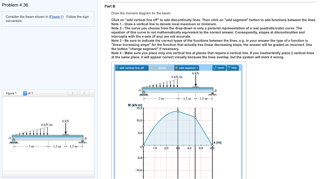
Figure 1 click on add vertical line off to add discontinuity lines. Follow the sign convention. Problem 770 draw the shear diagram for the beam. Part a draw the moment diagram for beam follow sign. Note 2 you should not draw an extra discontinuity line at the. B draw the moment diagram for the beam.

Never a truer word spoken about both work and life in general. I saw this sign at a Thai Festival held annually in Poole, Dorset, UK
Irving H. Shames-Engineering Mechanics (Statics and Dynamics).(1996) - Free ebook download as PDF File (.pdf), Text File (.txt) or read book online for free. For Combined Statics and Dynamics courses.This edition of the highly respected and well-known book for Engineering Mechanics focuses on developing a solid understanding of basic principles rather than rote …
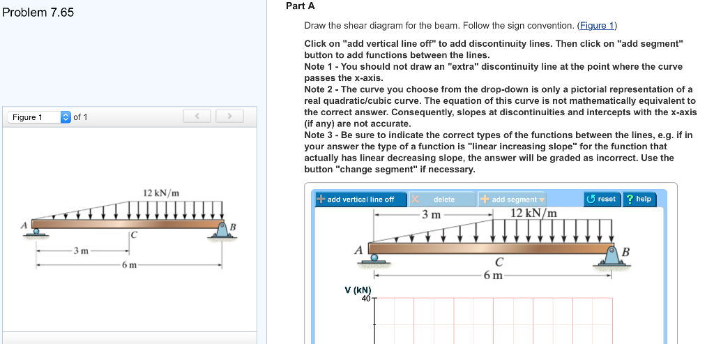
Solved: Problem 7.65 Of 1 Figure 1 3 M 12 KN/m 6 M Part A ...
Answer (1 of 2): EDIT 2020-09-14 Without explaining all the calculus to prove it, a simple rule of thumb is: 1. the change in shear = -(area under the load curve (w)) 2. slope of the V curve = -(w) 3. slope of the M curve = V 4. the change in M = area under the V curve. Here's how I got my numb...
Draw the shear diagram for the beam. Follow the sign ...
Answered: 7-76. Draw the shear and moment… | bartleby. Start your trial now! First week only $4.99! arrow_forward. We've got the study and writing resources you need for your assignments. Start exploring! Engineering Mechanical Engineering Q&A Library 7-76. Draw the shear and moment diagrams for the beam 15 kN 10 kN/m 20 kN · m А -2 m -1 m ...

Draw The Shear Diagram For The Beam Follow The Sign ...
1- Draw the FBD of the beam. In the FBD, the directions of the unknown force and moment are assumed positive according to the member sign convention. 2- Solve the equations of equilibrium for the support reactions. 3- Make a cut in the FBD of the beam at an arbitrary point x meter away from the left end of the beam as shown.

Photo was taken at a Switchfoot concert in San Diego, California.
beam from the left hand end and summing up the areas of shear force diagrams using proper sign convention. xThe process of obtaining the moment diagram from the shear force diagram by summation is exactly the same as that for drawing shear force diagram from load diagram.
Draw The Shear Diagram For The Beam Follow The Sign ...
Step 2 of 3. (A) Draw the free body diagram of the section of the beam at the range as shown in Figure (3). Here, horizontal location on the beam with respect to point A is x and the maximum magnitude of distributed load at the x location is y. Determine expression for the maximum magnitude of distributed load ( y) using similar triangles rule ...
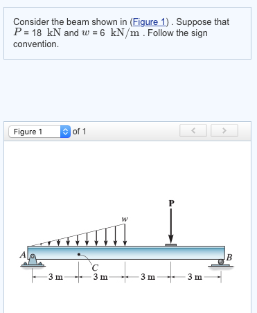
Solved: Consider The Beam Shown In (Figure 1) Suppose That ...
Problem 7.76 4 of 7 Rey Part A Draw the shear diagram for the beam. Follow the sign convention. (Figure 1) Click on "add vertical line off" to add discontinuity lines. Then click on "add segment" button to add functions between the lines. Note 1 - You should not draw an "extra" vertical line at the location of applied moment.
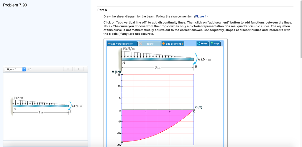
Solved: Problem 7.90. Draw The Shear Diagram For The Beam ...
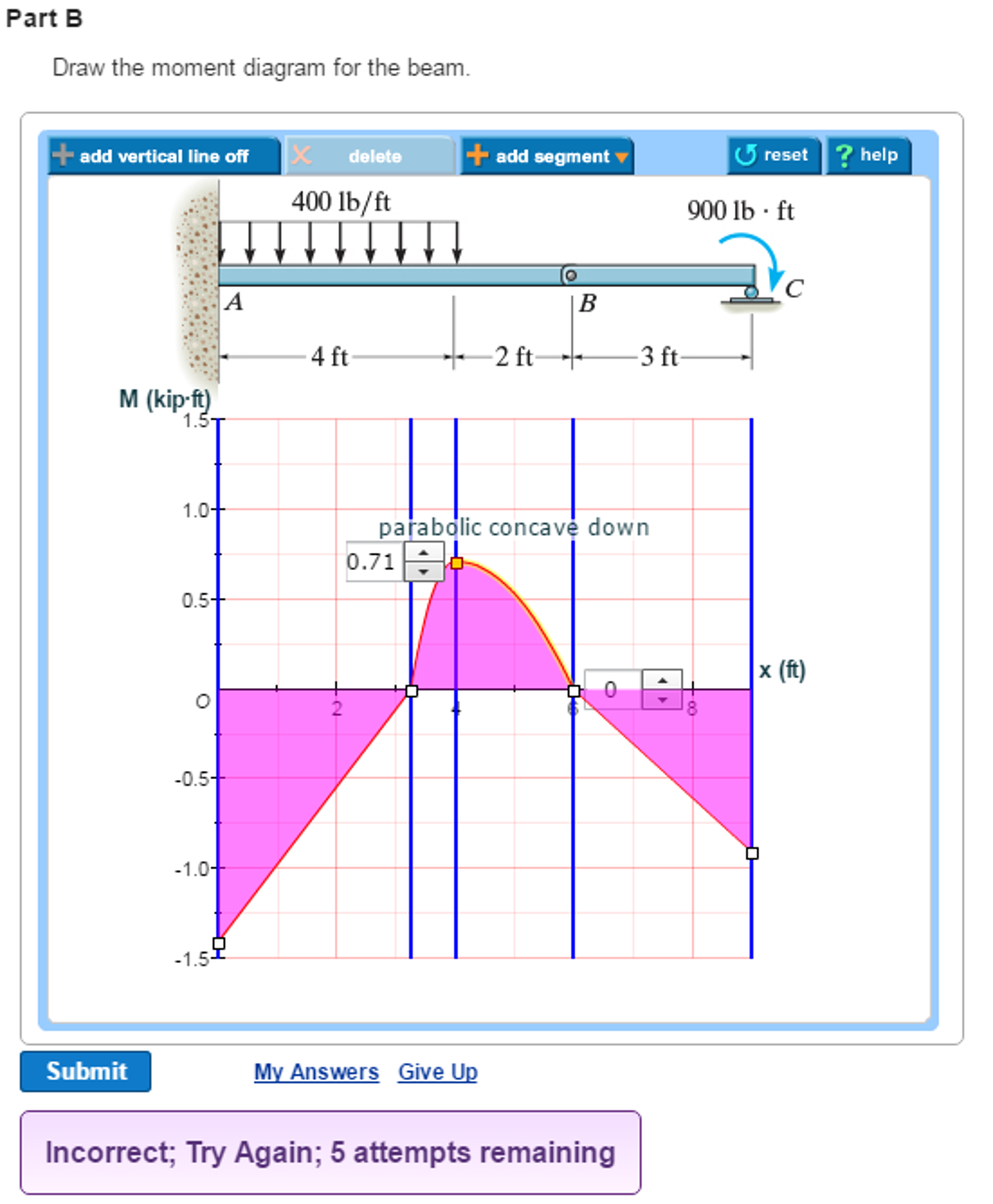
Solved: Draw The Moment Diagram For The Beam. Follow The S ...

With All Your Heart 2
Solved: Problem 7.56 3 Of 4 Part A Draw The Shear Diagram ...
Solved: Previous 12 Of 14 Problem 7.76 Draw The Shear Diag ...
Solved: 1) Draw The Shear Diagram For The Beam. Follow The ...

Draw The Shear Diagram For The Beam Follow The Sign ...
Solved: Draw The Shear Diagram For The Beam. Follow The Si ...
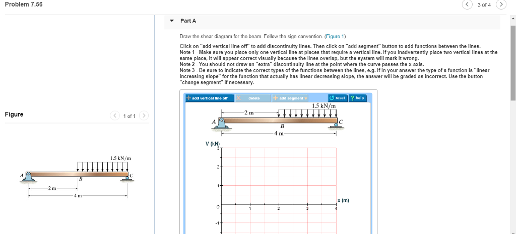
Solved: 1.5 KN/m - 4 M Part A Draw The Shear Diagram For T ...
Solved: Draw The Shear Diagram For The Beam. Follow The Si ...
Solved: Draw The Shear Diagram For The Beam. Follow The Si ...

Draw The Shear Diagram For The Beam. Follow The Sign ...
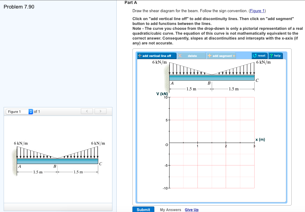
Solved: Problem 7.90 Part A Draw The Shear Diagram For The ...

I was in #MWC18 for 4 days. I was looking for a different perspective of technology and innovation. A human point of view.
Solved: Draw The Shear Diagram For The Beam. Follow The Si ...
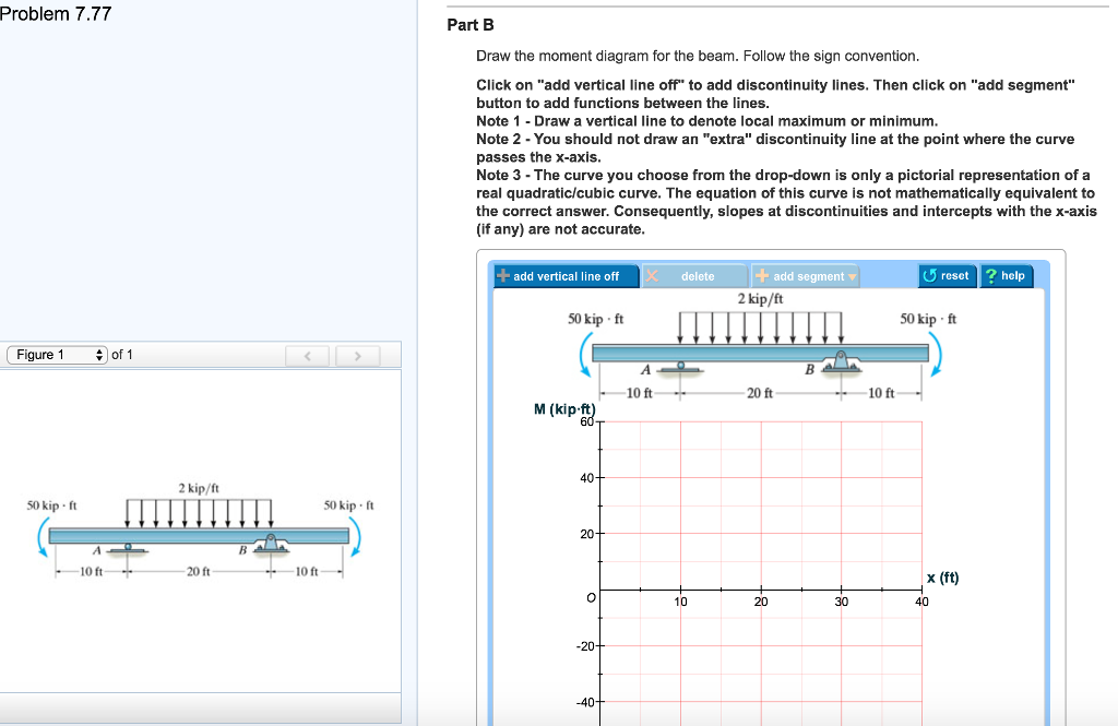
Solved: Problem 7.77 Part A Draw The Shear Diagram For The ...
Solved: Part A - Draw The Shear Diagram For The Beam. Foll ...

Draw The Shear Diagram For The Beam. Follow The Sign ...

Draw The Shear Diagram For The Beam Follow The Sign ...
Solved: Draw The Shear Diagram For The Beam. Follow The Si ...
Solved: Draw The Shear Diagram For The Beam. Follow The Si ...
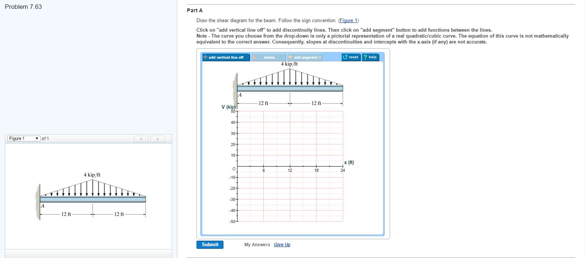
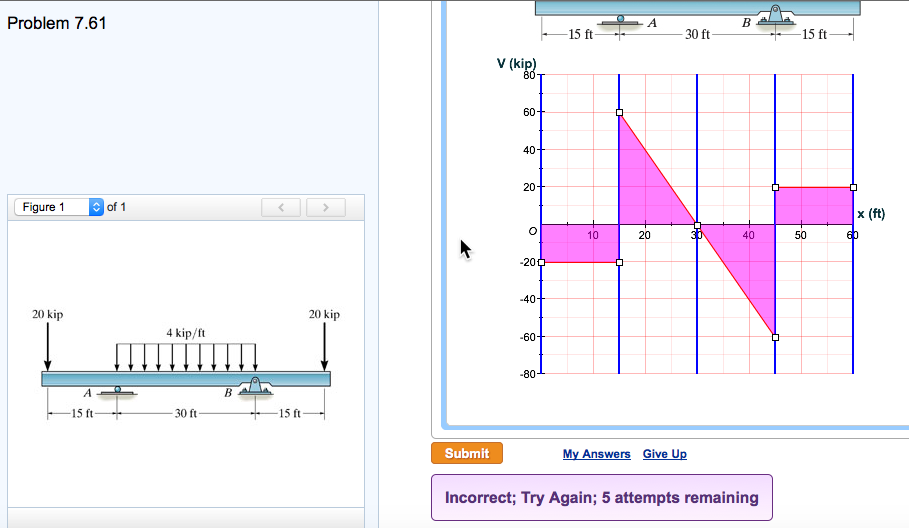
Solved: Problem 7.63 Part A Draw The Shear Diagram For The ...
Solved: Draw The Shear Diagram For The Beam Follow The Sig ...
Solved: Consider The Beam Shown In (Figure 1). Follow The ...
Solved: Part A Draw The Shear Diagram For The Beam. Follow ...

Solved: Draw The Shear Diagram For The Beam. Follow The Si ...
0 Response to "42 7.76 draw the shear diagram for the beam. follow the sign convention. (figure 1)"
Post a Comment