41 part winding start motor wiring diagram
ind560 user manual mettler dl 38, motor wiring diagram 12 lead dual voltage wye start delta run or part winding start motors designed by us motors for part winding start may also be used for across the line starting using only the full winding connection damage will occur if the motor is operated with load for more than 2 seconds on part ... Part Winding Start Motor Wiring Diagram from mrelectrician.tv Print the electrical wiring diagram off in addition to use highlighters to trace the routine. When you use your finger or perhaps the actual circuit together with your eyes, it's easy to mistrace the circuit. A single trick that We 2 to printing a similar wiring picture off twice.
In this video I cover the basics of an part winding motor starterFor other videos on reduced voltage starting methods:Wye-delta starter: https://youtu.be/kQU...

Part winding start motor wiring diagram
488076 motor wiring diagram 12 lead single voltage wye start delta run or part winding start motors designed by us motors for part winding start may also be used for across the line starting using only the full winding connection. In such case each cable will be marked with the appropriate lead number. Aug 04, 2021 · Motors designed for part winding start utilize only a portion of the winding at start up. Part winding start compressor wiring diagram wiring diagram is a simplified conventional pictorial representation of an electrical circuit it shows the components of the circuit as simplified shapes and the capability and signal associates surrounded by the devices. Circuit diagrams Autotransformer & part winding Autotransformer - HOA An autotransformer starter reduces inrush current by using a transformer in the line just ahead of the motor to step down the voltage applied to the motor terminals. By reducing the voltage, the current drawn from the line is reduced during start-up.
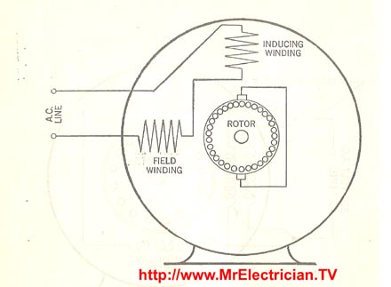
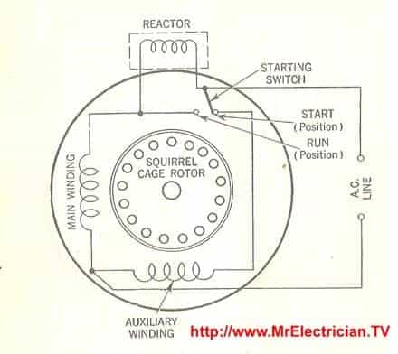
Part winding start motor wiring diagram. motor starts. The start sequence alerts the power company that the line needs more power. The Comparing Differences In Wye-Delta And Part-Winding-Start Connections 1 One common PWS connection divides the winding in half. 3 2 9 7 8 By Chuck Yung EASA Technical Support Specialist One of the most misunderstood winding connections is the part ... Aug 26, 2018 · MOTOR WIRING DIAGRAM 12 Lead, Single Voltage, Wye Start – Delta Run or Part Winding Start Revised: 1/8/ NIDEC MOTOR CORPORATION. Typical Wiring Diagrams Always use wiring diagram supplied on motor nameplate CONNECTION DIAGRAMS (#Co Leads Part Winding) WEG Three Phase Motors Volts / 12 Lead / Part Winding 12 10 11 12 3 L1 L2 12 10 11 64 5 78 9 12 L1 L2 12 10 11 64 5 L1 L2 Starting Type ( Volts) Across Line Starting Type ( Volts) Soft. motor leads 1237894&5&6 nema and iec nomenclature—12 leads single voltage or low voltage of dual-voltage motors t1 t2 t3 t7 t8 t9 nema 1,6 2,4 3,5 7,12 8,10 9,11 iec u1,w2 v1,u2 w1,v2 u5,w6 v5,u6 w5,v6 terminal markings and connections part winding start 12 9 6 3 11 8 5 2 10 1 7 4 w6 w5 w2 w1 v6 v5 v2 v1 u6 u1 u5 u2 nema iec nema nomenclature ... In split phase motors, changing the winding causes the motor to work in reverse. Both windings must be identical as to size of wire and number of turns. Use this when you need a reversible high-torque, intermittently rated capacitor type motor. Reactor Start Split Phase Induction Electric Motor. Reactor Start Split Phase Induction Electric Motor.
Nov 07, 2017 · Part Winding Start Motor Wiring Diagram. By Admin | November 7, 2017. 0 Comment. Part winding motor starters start connection electric motors generators engineering eng tips reduced voltage starter direct from galco electronics designed for utilize only a portion of the at up this means wind terminals terminal plate electrician talk control ... Describe the construction and operation of a part winding motor starter. • Draw and interpret diagrams for part winding motor starters. Part Winding Start Compressor Wiring Diagram - wiring diagram is a simplified conventional pictorial representation of an electrical circuit. It shows the components of the circuit as simplified shapes, and the capability and signal associates surrounded by the devices. Part Winding. This method used only a portion (usually one-half, but sometimes two-thirds) of the motor winding, increasing the impedance seen by the power system. It is to be used only for voltage recovery, and must not be left on the start connection for more than 2 to 3 seconds.
Motor Wiring Diagram 12 Lead, Single Voltage, Wye Start - Delta Run or Part Winding Start Motors designed by US Motors for Part-Winding Start may also be used for across the line starting using only the full winding connection. Damage will occur if the motor is operated with load for more than 2 seconds on part-winding without transition to full MOTOR WIRING DIAGRAM 466703 12 Lead, Single Voltage, Wye Start - Delta Run or Part Winding Start Revised: 1/8/2014 NIDEC MOTOR CORPORATION ST. LOUIS, MISSOURI. MOTORS . Title: Microsoft Word - 466703 Author: emd2324 Created Date: 1/8/2014 1:14:06 PM ... Capacitor Start Motors Diagram amp Explanation of How a. Single Phase Induction Motor Wiring Diagram taesk com. ... Basics of 3 phase Induction Motor part 1 EEP. Motor Connection 1 / 26. ... Electrical Motor calculator Wiring Diagram Apps on. Motor Winding Diagram Products amp Suppliers Engineering360. Basics of 3 phase Induction Motor part 1 What is part winding starter? '' Part-winding starters are used with motors having two separate and parallel windings in the stator, connected either wye or delta. This type of starting does not necessarily reduce the starting current but rather starts the motor incrementally, thereby splitting the inrush current in sections.
Single Phase Capacitor Start Motor Wiring Diagram ...
May 06, 2020 · Part Winding Start Motor Wiring Diagram. Part Winding Start Motor Wiring Diagram from mrelectrician.tv. Print the wiring diagram off plus use highlighters to trace the signal. When you make use of your finger or perhaps the actual circuit with your eyes, it is easy to mistrace the circuit. 1 trick that We 2 to printing a similar wiring plan off twice.
Part Winding Start Motor Wiring Diagram - Collection ...
always use wiring diagram supplied on motor nameplate. single-phase wiring diagrams always use wiring diagram supplied on motor nameplate for motors without thermal protection ... y only start ti-blu t2-wht t3.org t4-yel t5-blk t6-gry z a tio til t4 t5 t12 3 tio til t4 t5 t12

MOTOR START RELAYS BASICS AND TUTORIALS | TRANSMISSION ...
Motor Wiring Diagram Single Voltage, Wye or Delta Connection Part Winding Start (PWS) Or Full Winding - Across the Line Start To reverse direction of rotation, interchange leads L1 & L2. Each lead may have one or more cables comprising that lead. In such case, each cable will be marked with the appropriate lead number.
Part Winding Start Motor Wiring Diagram – Collection ...
MOTOR WIRING DIAGRAM 12 Lead Single Voltage Wye Start Delta Run or Part Winding Start Revised. Part winding start compressor wiring diagram . 18 NIDEC MOTOR CORPORATION. Typical Wiring Diagrams Always use wiring diagram supplied on motor nameplate CONNECTION DIAGRAMS Co Leads Part Winding WEG Three Phase Motors Volts 12 Lead Part Winding.

Part Winding Start Compressor Wiring Diagram - easywiring
Wiring diagrams for the various configurations are below. If you are unsure, please feel free to contact us. We are happy to explain further or talk about custom options if you don't see what you're looking for. Figure 1: Parts JCXX06P1X-XX - 3phase Starter with Start/Stop button, direct- online wiring diagram

Wiring diagram 230v cscr start circuit
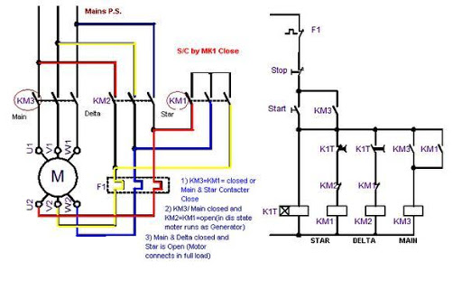
The post start with a wrong winding diagram, this drawing belongs to one two speed one winding motor (dahlander),and post sayd Part Winding, later we have receive a semi-hermetic compressor name plate and exetrnal wiring, both belongs to part winding motor.

Typical Connection Diagrams Three Phase Motors - "Y" Start ...
Part winding motor starters connection electric start overload terminals at the terminal plate 12 wire 3 phase. Motor Wiring Diagram 12 Lead Single Voltage Wye Start - Delta Run or Part Winding Start Motors designed by US Motors for Part-Winding Start may also be used for across the line starting using only.
50 Electric Fan Motor Winding Diagram - Wiring Diagram Plan
3Ø WIRING DIAGRAMS 1Ø WIRING DIAGRAMS Diagram ER9 M 3~ 1 5 9 3 7 11 Low Speed High Speed U1 V1 W1 W2 U2 V2 TK TK Thermal Overloads TWO SPEED STAR/DELTA MOTOR Switch M 3~ 0-10V 20V 415V AC 4-20mA Outp uts Diagram IC2 M 1~ 240V AC 0-10V Outp ut Diagram IC3 M 1~ 0-10V 4-20mA 240V AC Outp uts These diagrams are current at the time of publication ...

Help Please ~ Wiring the Switch to the motor - Page 2
2 Speed, 2 Winding, Single Voltage, Wye Connected, With Current Transformers, Lightning Arrestors & Surge Capacitors; Low Speed Winding: 466703 : 12 Lead, Wye Start - Delta Run or PWS Single Voltage Assembled in Conduit Box: 488075 : Wye Start Delta Run or PWS Connection, 12 Lead, Dual Voltage: 488076

water falls on rocky shore during daytime
Note: Suitable for unit previously approved for part winding start (a standard. Star - Y 230/460 9 lead motor may often be used for 230V part winding - a.1 page

trees in forest
Starter Motor Wiring Diagram – auto starter motor wiring diagram, basic starter motor wiring diagram, bosch starter motor wiring diagram, Every electrical arrangement is made up of various diverse parts. Each component should be set and connected with different parts in specific manner. If not, the structure will not work as it ought to be.
Weg Part Winding Start Wiring Diagram 12 Lead
Stromdämpfung beim Start und nied- ... Part Winding Motor (PW) Content 1 General 2 Construction 3 Electrical connection 1 General When 3-phase asynchronous motors are started direct on line an inrush current occurs which is, according to ... 3.1 Schematic wiring diagram and motor connection 3 Raccordement électrique 3.1 Schéma de ...

Patent US3761792 - Switching circuit for motor start ...
This type of motor requires no connection diagram because the electrician simply connects the three motor leads (which may be labeled T1, T2 and T3) to the ...

6 Lead Wye Start Delta Run Wiring / 6 Lead Wye Start Delta ...
4/5/2018 Part Winding Start: How It Works and Advantages ... Motors that divide the winding in half will se e a 50% reduction in current at start-up. Motors that split the winding two thirds to one third energizing two thirds will see a current reduction of 33% at start-up. A couple of advantages of using part windi ng start is to minimize ...

Starter Control Circuit Components
Circuit diagrams Autotransformer & part winding Autotransformer - HOA An autotransformer starter reduces inrush current by using a transformer in the line just ahead of the motor to step down the voltage applied to the motor terminals. By reducing the voltage, the current drawn from the line is reduced during start-up.

Start Capacitor & Inrush Facts and Myths - Part #1 - HVAC ...
Aug 04, 2021 · Motors designed for part winding start utilize only a portion of the winding at start up. Part winding start compressor wiring diagram wiring diagram is a simplified conventional pictorial representation of an electrical circuit it shows the components of the circuit as simplified shapes and the capability and signal associates surrounded by the devices.

Tech@electrical india : Single Phase Induction Motor and ...
488076 motor wiring diagram 12 lead single voltage wye start delta run or part winding start motors designed by us motors for part winding start may also be used for across the line starting using only the full winding connection. In such case each cable will be marked with the appropriate lead number.

35 Part Winding Start Motor Wiring Diagram - Wiring ...
Capacitor Start 220v Single Phase Motor Wiring Diagram ...

3Hp Single Phase Induction Motor Winding | Electric Motor ...

person in red jacket and black pants standing on snow covered ground during daytime

Pin on Electrical Concepts

horses on green grass field near body of water during daytime

KBREEE: Capacitor Start Induction Motors

Zoeller Pumps Wiring Diagram With Thermal Overload Single ...
Part-winding connection - Electric motors & generators ...
Download Star delta wiring diagram on PC & Mac with ...

Multiple Speed Single-Phase Fan Motor

PART WINDING START BITZER COMPRESSOR WIRING DIAGRAM - Auto ...

Patent US6271639 - Capacitor start single phase induction ...

43 Dahlander Motor Winding Diagram - Wiring Diagram Source ...
Weg Part Winding Start Wiring Diagram 12 Lead
Why is it necessary to switch off the centrifugal switch ...

Motor Winding Connection Diagram» All Motor Winding ...

empty concrete road
grayscale photography of International Motor Trucks store

Ceiling Fan Starting And Running Winding Connection ...
Starter motor, starting system Part 2

athletic's on starting line during daytime

480V 3 Phase 6 Lead Motor Wiring Diagram : Weg Part ...
yellow blue and black coated wires
0 Response to "41 part winding start motor wiring diagram"
Post a Comment