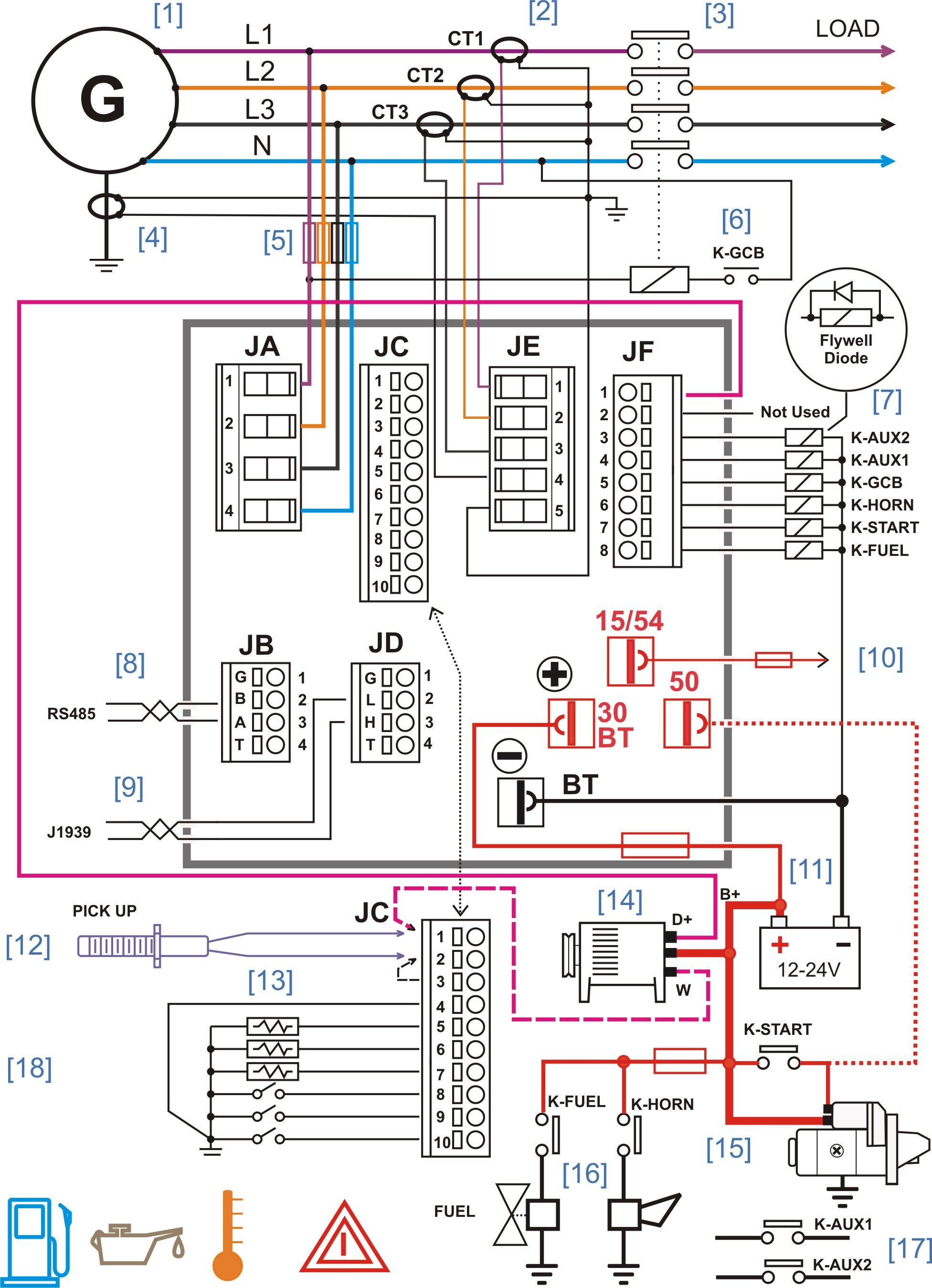
41 kohler transfer switch wiring diagram
Transfer Functions. Standard-transition operation with either automatic or non-automatic control. Standard-transition transfer time less than 100 milliseconds (6 cycles @ 60 Hz) Double-throw, mechanically interlocked design (break-before-make power contacts) Solid, switched or overlapping (make-before-break) neutral. Jan 16, 2020 · January 16, 2020 by faceitsalon. kohler transfer switch wiring diagram – What is a Wiring Diagram? A wiring diagram is a simple visual representation of the physical connections and physical layout associated with an electrical system or circuit. It shows the way the electrical wires are interconnected which enable it to also show where fixtures and components could be coupled to the system.
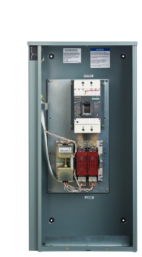
ATS. KOHLER® transfer switches bridge the gap between loss of utility and standby power. Featuring Kohler designed and built MPAC® controllers, they're factory-tested to ensure transfer of power from the utility to the generator and back again. Learn More.
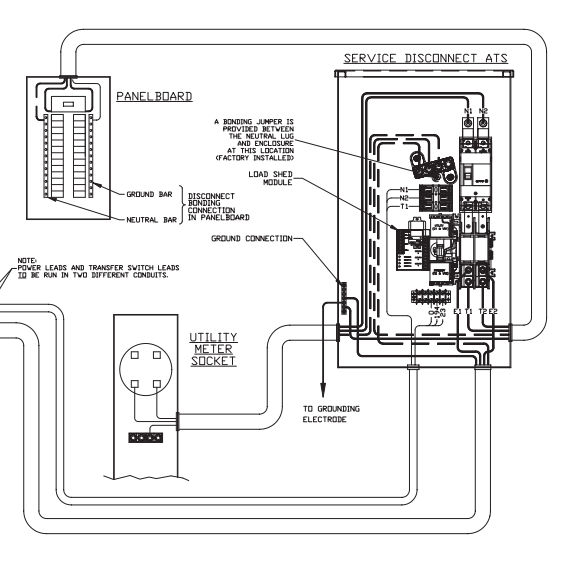
Kohler transfer switch wiring diagram
Nolan Web Development is coming soon. Electrical Wiring Be28 Automatic Transfer Switch Controller Connections Diagra Diagrams# : Kohler Ats Wiring-diagram (+89 ... A bypass-isolation transfer switch bundles an automatic and a manual transfer switch into a single unit. Bypass isolation is used to transfer power to the manual switch to allow servicing of the ATS while maintaining power to the facility. When the primary automatic transfer switch is in test or isolate position, the manual transfer switch is ... May 03, 2018 · August 9, 2018. May 3, 2018 by headcontrolsystem. Variety of kohler transfer switch wiring diagram. A wiring diagram is a streamlined traditional pictorial depiction of an electric circuit. It shows the parts of the circuit as streamlined shapes, and the power and also signal links in between the devices. A wiring diagram normally provides information about the loved one placement as well as plan of gadgets and also terminals on the devices, to assist in structure or servicing the tool.
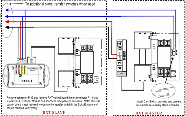
Kohler transfer switch wiring diagram. Model RXT Automatic Transfer Switch The Model RXT automatic transfer switch is designed for use only with Kohlerr generator sets equipped with RDC2 or DC2 generator set/transfer switch controls. The transfer switch operation is controlled by the RDC2/DC2 controller. Standard Features D Allows utility voltage display on the RDC2/DC2 generator ... A wiring diagram is a streamlined standard photographic representation of an electrical circuit. Rxt switch pdf manual download. Assortment of kohler transfer switch wiring diagram. Record field installed kit numbers after installing the kits. It shows the parts of the circuit as streamlined shapes and also the power and signal links between ... The Model RXT automatic transfer switch is designed for use Refer to the transfer switch dimension drawings and wiring diagrams for planning and installation. G11-140 (Model RXT Automatic Transfer Switch) 3/20g Page 3 SiteTecht software, which is only available to Kohler-authorized distributors and dealers. Priority Setting Wiring Diagram Version No. Kohler generator manual l0402312 standby on off switch diy 12 000 watt bspp home system 25 150rezg wiring diagrams power automatic transfer diagram 14resal 14 air cooled 20resal installation with 200 amp ats 20rescl 200sels 20kw composite starter generators parts 3 phase 12resvl 12kw s for rxt 100 service entrance kcs ...
For a complete description of the transfer switch part number, see ''Explanation of Kohler Part Number". 1. Record transfer switch part number on the following page. Example: K-566341-0150 2. Determine group in which service part is needed using figure 1, page 3. Example: Need enclosure door. 3. Locate the NEMA Type 1 section in ... Available in service-entrance models. Includes RXT single phase combined interface/load management board. Optional external LED display or optional external LED display with load management. Corrosion-resistant aluminum enclosure. 5-year, 2000-hour limited warranty. 200-amp models available. Volts: 240 V (single-phase). KOHLER® transfer switches bridge the gap between loss of utility and standby power. Featuring Kohler designed and built MPAC® controllers, they're factory-tested to ensure transfer of power from the utility to the generator and back again. Transfer switches are available in standard, bypass-isolation and service-entrance configurations with ... Kohler transfer switch K-164231-0225 23G Serial K24143 ... With that he can identify the proper wiring diagram and then call a legacy distributor (again, as described in the posts at the top of the forum which everyone should read before asking questions) and get a wiring diagram.
Transfer Switch Identification Numbers Record the product identification numbers from the transfer switch nameplate. Model Designation Serial Number Accessories - Alarm Board - Battery Module - California OSHPD Approval - Controller Disconnect Switch - Current Monitoring - Digital Meter - Heater - IBC Seismic Certification - I/O Module ... 4 Schematics and Wiring Diagrams TP-6918 2/16 Schematics and Wiring Diagrams Model Description Part Number Schematic Wiring Diagram KSS Standard Transition, Specific Breaker, 40--260A GM89713 GM89714 Standard Transition, Specific Breaker, 400--600A GM89715 GM89716 Standard Transition, Specific Breaker, 800--1000A GM89717 GM89718 KSP Sep 24, 2021 · A wiring diagram is a simple visual representation of the physical connections and physical layout associated with an electrical system or circuit. Kohler transfer switch wiring diagram. Determine the wiring diagram numbers for your unit. Attach the connectors to the wires using PVC cement. Transfer Switch Controls ... Wiring Diagram is a schematic drawing of the wiring of an electrical system. Spec Sheets ... One more reason to spec KOHLER.
Wiring Diagram Ac Generator Valid Modern Dc Wiring Gallery Circuit Diagram Electrical Circuit Diagram Diagram . Electrical Wiring Be28 Automatic Transfer Switch Controller Connections Diagra Diagrams Kohler A Transfer Switch Electrical Circuit Diagram Wiring Diagram . Cutler Hammer A831443 7 Unit Wiring Diagram In 2021 Diagram Electrical ...
generator set/transfer switch controller, available exclusively ... Refer to the transfer switch dimension drawings and wiring diagrams for planning and ...6 pages
Transfer Switch Identification Numbers Record the product identification numbers from the transfer switch nameplate. Model Designation Serial Number Accessories - Alarm Board - Battery Module - Controller Disconnect Switch - Digital Meter - Heater - I/O Module, Standard (max. 4) qty: - I/O Module, High Power (max. 4) qty: - Load Shed - Line ...
Sep 02, 2018 · The automatic transfer switch ats continuously monitors the power coming from your utility. Kohler ats wiring diagram. Dynagen designs manufactures and supports a wide variety of generator controls kits. View and download kohler kcs operation and installation online. Welcome to a2z military collectables.
This diagram explains the Kohler Transfer Switch model numbering system. The sample number shown is for a microprocessor-logic automatic transfer switch, 480-Volt, 60-Hertz, 3-phase, 3-pole, 4-wire, 150-ampere model in a NEMA Type 1 enclosure. Voltage & Frequency Phase-to-Phase 240V AC Max. 600V AC Max. 600V AC Max. Available in 30-100 ampere ...
4 Wiring Diagrams TP-6712 4/10 Wiring Diagrams Use the Wiring Diagram Cross-Reference chart to determine the wiring diagram version number for a given model number and spec number. Then find that version number, the controller type, and the alternator type on the Wiring Diagrams Reference chart to determine the wiring diagram numbers for your unit.
of the switch in amperes: Record the transfer switch model designation in the boxes. The transfer switch model designation defines ratings and characteristics as explained below. Sample Model Designation: RXT-JFNC-0200A 0100 0150 0200 0300 0400 Note: GM85273-SA_ is a 100 amp single-phase model with a 12-circuit load center and NEMA 1 enclosure.
A wire crimper, particle IOT device, magnetic reed switch, laptop, and jumper wires at the start of an internet of things connected project
May 03, 2018 · August 9, 2018. May 3, 2018 by headcontrolsystem. Variety of kohler transfer switch wiring diagram. A wiring diagram is a streamlined traditional pictorial depiction of an electric circuit. It shows the parts of the circuit as streamlined shapes, and the power and also signal links in between the devices. A wiring diagram normally provides information about the loved one placement as well as plan of gadgets and also terminals on the devices, to assist in structure or servicing the tool.
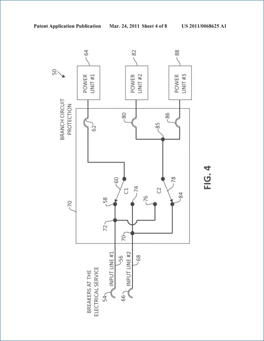
A bypass-isolation transfer switch bundles an automatic and a manual transfer switch into a single unit. Bypass isolation is used to transfer power to the manual switch to allow servicing of the ATS while maintaining power to the facility. When the primary automatic transfer switch is in test or isolate position, the manual transfer switch is ...
Nolan Web Development is coming soon. Electrical Wiring Be28 Automatic Transfer Switch Controller Connections Diagra Diagrams# : Kohler Ats Wiring-diagram (+89 ...


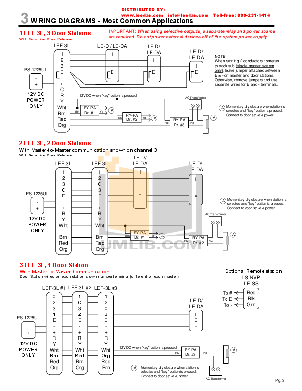







![[SZ_7878] Automatic Transfer Switch On Three Phase Manual ...](https://static-resources.imageservice.cloud/1635118/kohler-automatic-transfer-switch-wiring-diagram-wiring-diagram-m6.jpg)
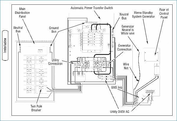
![[DIAGRAM] Kohler Automatic Transfer Switch Wiring Diagram ...](https://www.outsidesupply.com/product_images/images/images/transfer-switch-wiring_diagram.jpg)





0 Response to "41 kohler transfer switch wiring diagram"
Post a Comment