39 regenerative braking circuit diagram
An embodiment of the present invention is illustrated in FIG. 3 which shows a regenerative brake control circuit operated at a speed higher than the rated speed of the motor. The diagram of FIG. 4...
Contents: Applications of Regenerative Braking; Regenerative Braking in DC Shunt Motors; Regenerative Braking in DC Series Motors; Under this condition, the back emf E b of the motor is greater than the supply voltage V, which reverses the direction of motor armature current. The machine now begins to operate as a generator and the energy generated is supplied to the source.
Regenerative Braking circuit. Ask Question Asked 9 years, 1 month ago. Active 3 years, 1 month ago. Viewed 9k times 3 1 \$\begingroup\$ I am ... In fact, take the two diagrams where current is flowing through Q2 and Q3 in that section and delete Q1 and Q4. You now have the half-bridge of topic 4. \$\endgroup\$ - pjc50.
Regenerative braking circuit diagram
Regenerative Braking System In Automobiles Circuit Diagram Homemade Projects. Regenerative braking system what is it how plugging dynamic works in control algorithm bldc motor driven electric vehicle diagram hydraulic blended types of a dc strategies ultra capacitor based bicycle by use case investigation international journal soft computing for fuel cell amplifier servo motion application ...
Introduction to Regenerative Braking 2. Difficulties Encountered in Regenerative Braking 3. Calculations of Energy Returned during Regeneration 4. Advantages and Disadvantages. Introduction to Regenerative Braking: Regenerative braking is an inherent characteristic of dc shunt wound motors and does not require any change of connections.
regenerative braking circuit. Schematic diagram of DC motor working as a motor and a regenerative brake Simulation fig3. We collect lots of pictures about Dc Electrical Regenerative Circuit Diagram. and finally we upload it on our website. Many good image inspirations on our internet are the very best image selection for Dc Electrical ...
Regenerative braking circuit diagram.
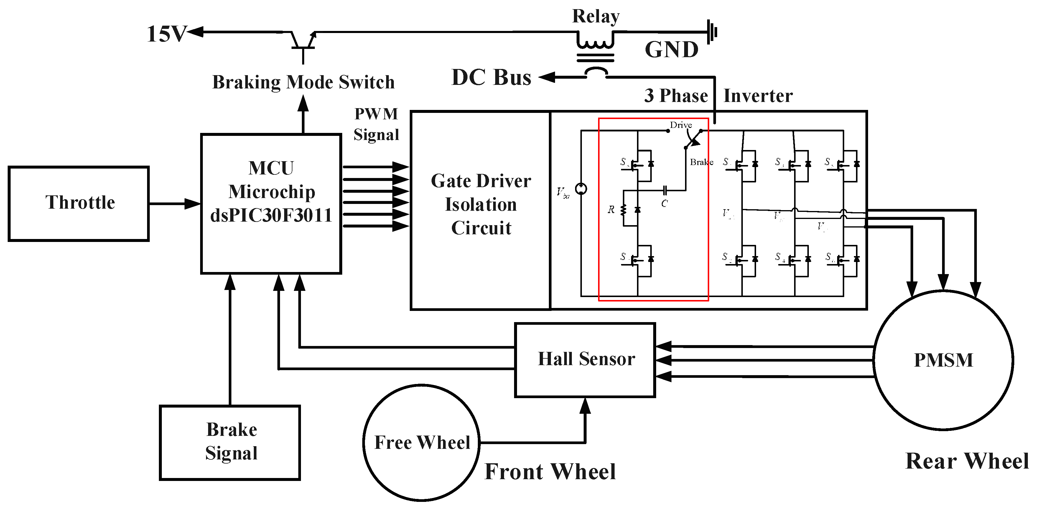
the battery. Thus, both the electric brake and energy regeneration are achieved. Thus far, many articles have discussed the braking energy regeneration of the EV [1]-[10].The so-called energy regenerative brake mainly employs the back electromotive force (EMF) of the motor in the braking process.
Regenerative braking is executed by drawing current from the alternator to charge the battery that is supplying the Page 9 of 103 circuit and the alternator. This can be done by controlling the field using the microcontroller and the software. Another technique that was utilized was the House of Quality analysis technique.
Regenerative Braking System in Automobiles (Circuit Diagram) The following regenerative electricity generator circuit in cars and motorcycles was inspired from the oscillating dolls, and idols inside vehicles which may be seen constantly swaying and moving due to the vehicle's uneven motion or whenever brakes are applied.
Patent Us Regenerative Braking Circuit Utilizing Drawing 3 phase motor starter connection. ponent Scr Dc Motor Control Speed Using Project Regenerative Braking Block Di wiring. We collect lots of pictures about Regenerative Braking Circuit Diagram. and finally we upload it on our website. Many good image inspirations on our internet are the ...
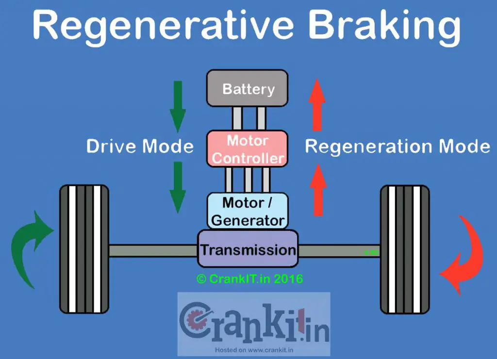
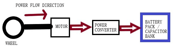
Regenerative Braking Diagram HowStuffWorks This simple diagram shows how a regenerative braking system is able to recapture some of the vehicle's kinetic energy and convert it into electricity. This electricity is then used to recharge the vehicle's batteries.
Brake chopper. Typically, a braking circuit (sometimes known as the "chopper" circuit) is controlled by the drive and consists of a power transistor and resistor (s) that are connected across the drive's DC bus. Brake transistor circuit. F5 drives come in both 200V and 400V models. Working with a 400V model F5 on a 3-phase supply voltage ...
An inverter device which delivers a-c power to an induction motor during motoring and receives power therefrom during regenerative braking has a current commutating capability which varies with the input voltage. During the regenerative braking mode of operation, the input voltage is increased by inserting an impedance in series between the d-c power source and the inverter, thereby increasing ...
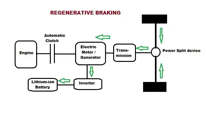
Regenerative Braking Systems (RBS) (Future Of Braking Systems) 76 Fig.3: Block Diagram of Regenerative Braking System. This advancement of technology in braking system controls the speed of the vehicle by converting some amount of the vehicle's kinetic energy into another useful form of energy. The energy so produced can
Regenerative Braking System Diagram Schematic And Image 07. Regenerative braking system plugging dynamic control algorithm investigation of how works in what is it energy brakes diagram electric vehicles bldc motor driven vehicle a use case sd controller with strategies for the fuel cell ultra capacitor based bicycle power monitor amplifier servo motion application automotive improving ...
There is disclosed a low-cost regenerative brake control circuit used for electric cars and the like which is capable of effecting regenerative braking on motors continuously over the range from a speed higher than the rated speed of the motors to a low speed and which comprises two motor circuits each including a series-connected motor and a reactor, each motor circuit being connected in ...
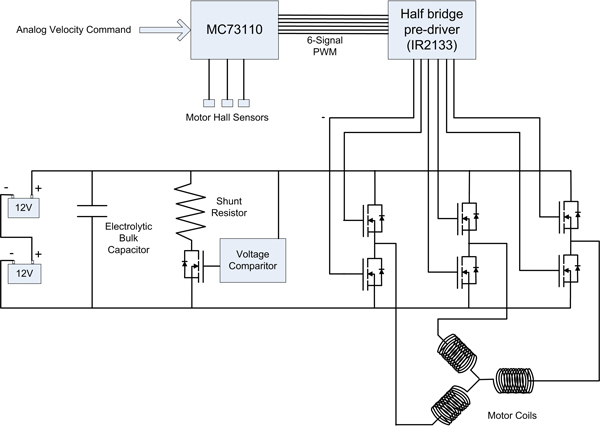
Using a boot strap driver. Then use a parallel sense resistor or shunt for the high side to detect positive of negative current flow. Then use that sense with an op-amp to control the PWM for regenerative braking. I could then set a given amount of regen via PWM or have it increase if it senses more reverse current.
The extra energy obtained from braking is used for light the bulb. 1.1 BRAKING SYSTEM All electric machines have two mechanical operations, motoring and braking. The nature of braking can be regenerative, where the kinetic energy of the rotor is converted into electricity and sent back to the power source or non-.
Enhanced regenerative braking strategies forelectric vehicles ...
The regenerative braking uses complex electronic circuits to choose between the forward/reverse direction of rotation of the motor. In some cases, manufacturers use capacitors to store the electrical energy for later use. Keeping the battery fully charged, especially in electric vehicles, is very helpful. It extends their driving range.
Regenerative braking circuit - electrical engineering stack ...
Regenerative (REGEN) braking is an effective method to increase the driving range of Hybrid Electric Vehicles (HEV) by minimising vehicle fuel consumption ( 1 ). The brake energy generated in a deceleration event can be stored by ways of numerous technologies. Those have thus far been developed to different degrees.

Types of braking in a dc motor | electrical4u
A logic diagram of the pro- posed regenerative braking control algorithm is shown in Figure 1 1. With a driver operating the brake pedal, the total braking demand T b need of a vehicle can be cal ...
Actuators | free full-text | active control of regenerative ...
Mar 12, 2021 - Regenerative Braking Circuit Diagram . Regenerative Braking Circuit Diagram . Regenerative Braking Luxury Circuit Diagram Regenerative Braking. Yi Yao Dc Motor Controller and Tachometer Speed Schematic Wiring. Ponent Scr Dc Motor Control Speed Using Project Regenerative
Hybrid regenerative braking system for electric vehicles ...
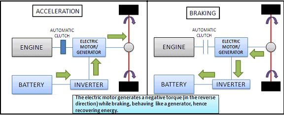
Regenerative braking helps in extending the range of the electric vehicle by 8-25%. Apart from saving energy and enhancing the range, it also helps in effective control of the braking operation. In the mechanical braking system, a reverse torque is exerted on the wheel when we press the brake pedal. Similarly, in the regenerative braking mode ...
Regenerative braking safety system and method of use - patent ...
the form of low current under non-braking condition. The model of regenerative braking system Supercapacitor model. According to the equivalent circuit diagram shown in Figure 2, the supercapacitor model of the braking energy storage unit is established, which consists of ideal capacitor and equivalent resistor.
Regenerative braking - a use case
Regenerative Circuit We will design a circuit to return energy from the motor to the battery when the bicycle is braking. This is known as regenerative braking. By controlling which MOSFETs are closed during a given motor state, we can redirect current back in to the battery.
Clemson vehicular electronics laboratory: regenerative braking
When re- generative braking is engaged (using a switch on the handle bar), the regenerative braking circuit cuts the connection from the controller to the motor and instead puts a load on the motor because of some very low resistance components like shunts. A shunt is basically a very low resistance resistor placed in a circuit.

Regenerative brakes - automotivesdictionary.com
Dynamic brakes are typically rated for duty cycles in the 20 percent range, and choppers are often used in heavier-duty applications. Simplified schematic of a dynamic braking circuit. Image credit: Rockwell Automation, Inc. There are two types of control for dynamic braking: hysteresis control and PWM (pulse-width modulation) control.
Regenerative braking circuit - electrical engineering stack ...
Whenever the back-EMF is greater than this voltage, you get regenerative braking. This will happen whenever the PWM duty cycle decreases faster than external forces (friction, for example) will slow the motor. Any resistance in the circuit reduces the energy you can recover from the mechanical load.

Structure principle diagram of regenerative braking system ...
3. Initial and final energies and overall braking efficiency. 13 4. Initial and final capacitor charge and average current while braking. 13 Figure 1. A 650 Farad Ultracapacitor 3 2. Overall block diagram of regenerative braking system 5 3. Cross sectional view of a hub motor 6 4. Variable braking scheme. 7 5.

Regenerative braking system by international journal of ...

Dunia kereta - 3 cara optimalkan regenerative braking pada ...
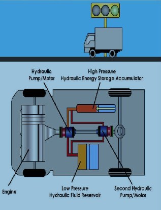
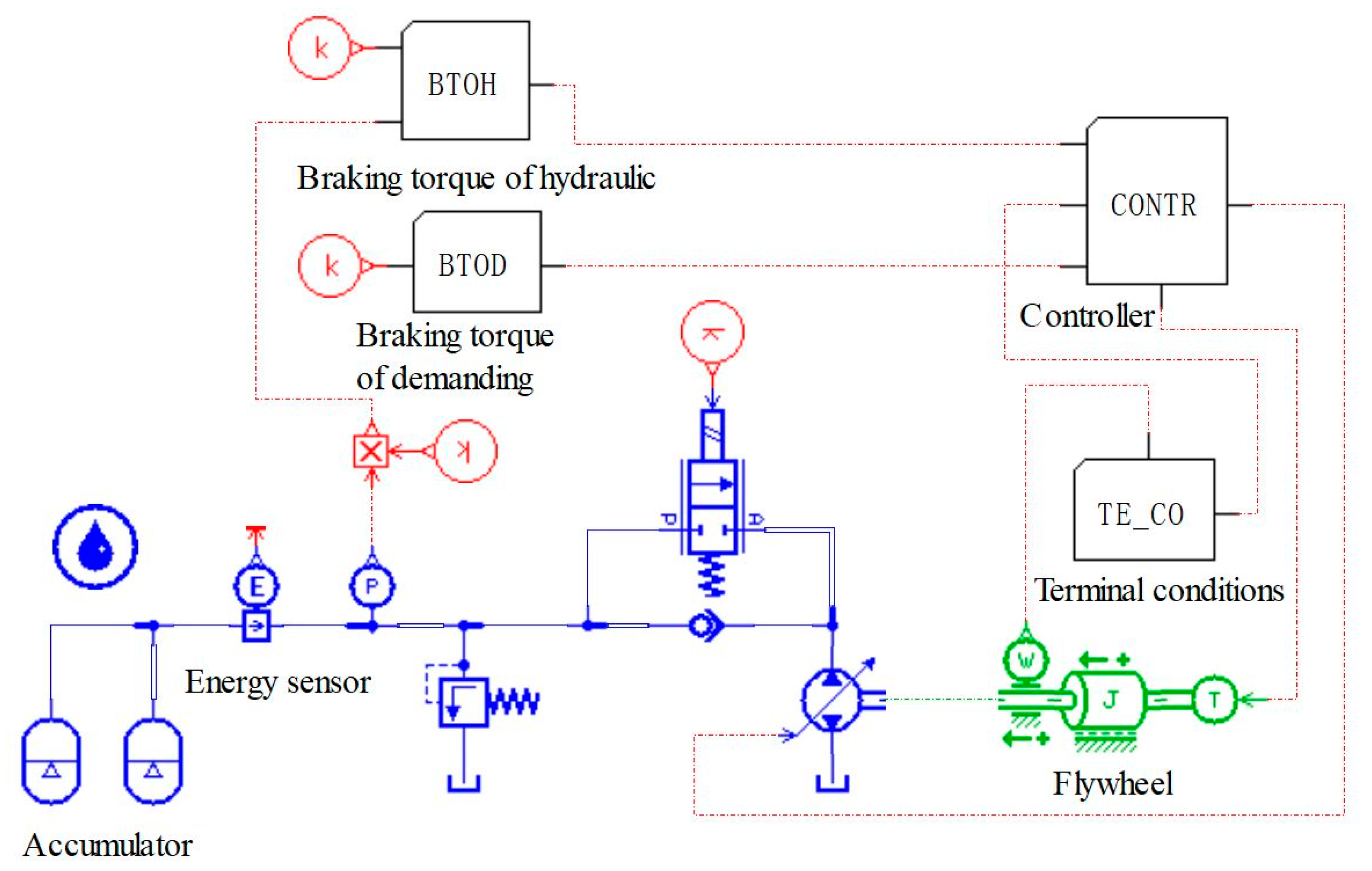
Microsoft word - hydraulic-regenerative-braking-system
Regenerative braking: what is it & how does it work ...

A new electric braking system with energy regeneration for a ...

What is braking? types of braking | regenerative plugging ...

A review on regenerative braking in electric vehicle ...
Regenerative braking system

How do regenerative brakes work? - explain that stuff

Regenerative braking system - diagram, schematic, and image 07
How regenerative braking works in electric vehicles

Logic diagram of the regenerative braking control algorithm ...
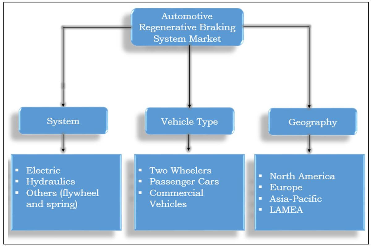
Automotive regenerative braking system market size, trends
Regenerative braking system for automobile

How does regenerative braking work? | skill-lync

Regenerative braking system - diagram, schematic, and image 02

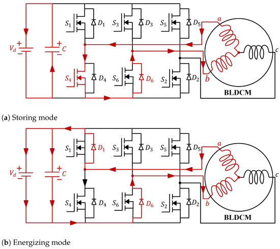
Regenerative braking circuit for a bldc motor - electrical ...

Regenerative brake control of dc motors using arduino ...
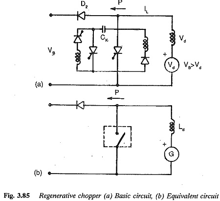
Regenerative braking | regenerative chopper basic circuit

Structure of single-axle series regenerative braking system ...
Applied sciences | free full-text | improving energy recovery ...
Variable switch regenerative braking technique for pm bldc ...

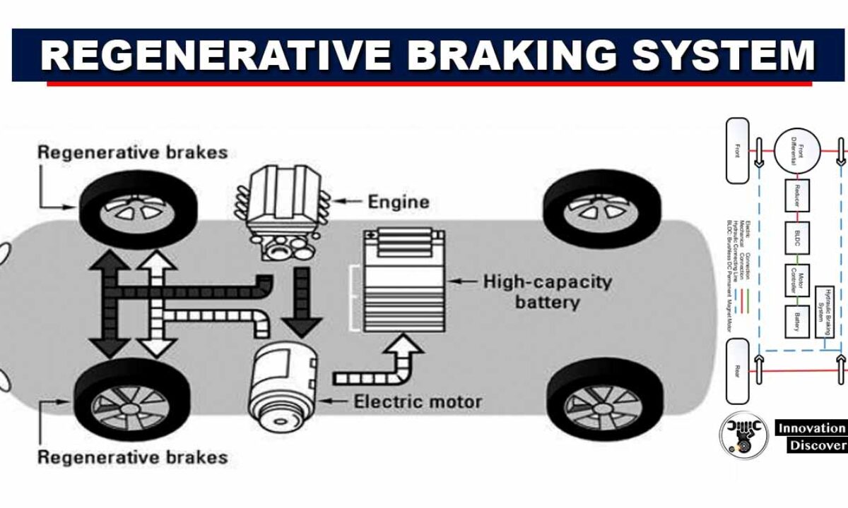
Major components of a regenerative braking system[4 ...

Scenario diagram of the regenerative braking system ...

Regenerative braking for fuel cell hybrid system with ...

Energy efficiency in transportation: electric petrol hybrid ...
Applied sciences | free full-text | investigation of ...
0 Response to "39 regenerative braking circuit diagram"
Post a Comment