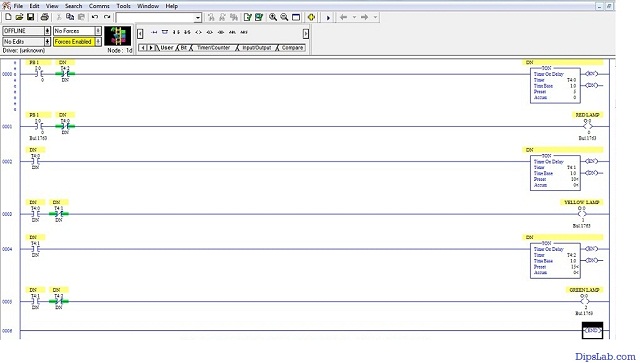
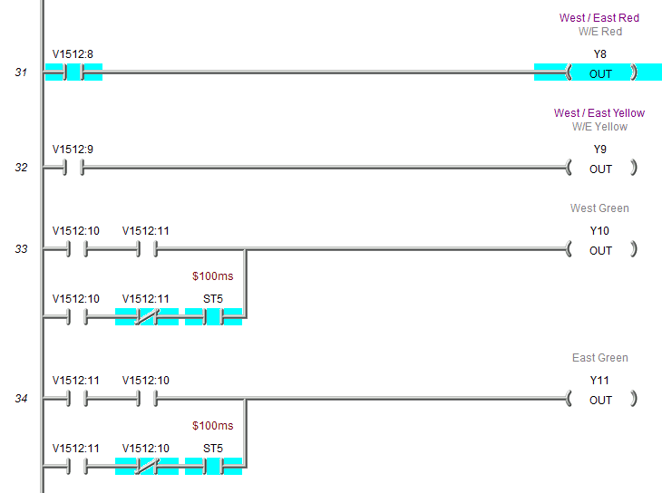
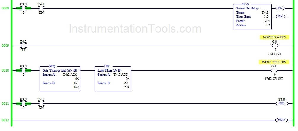
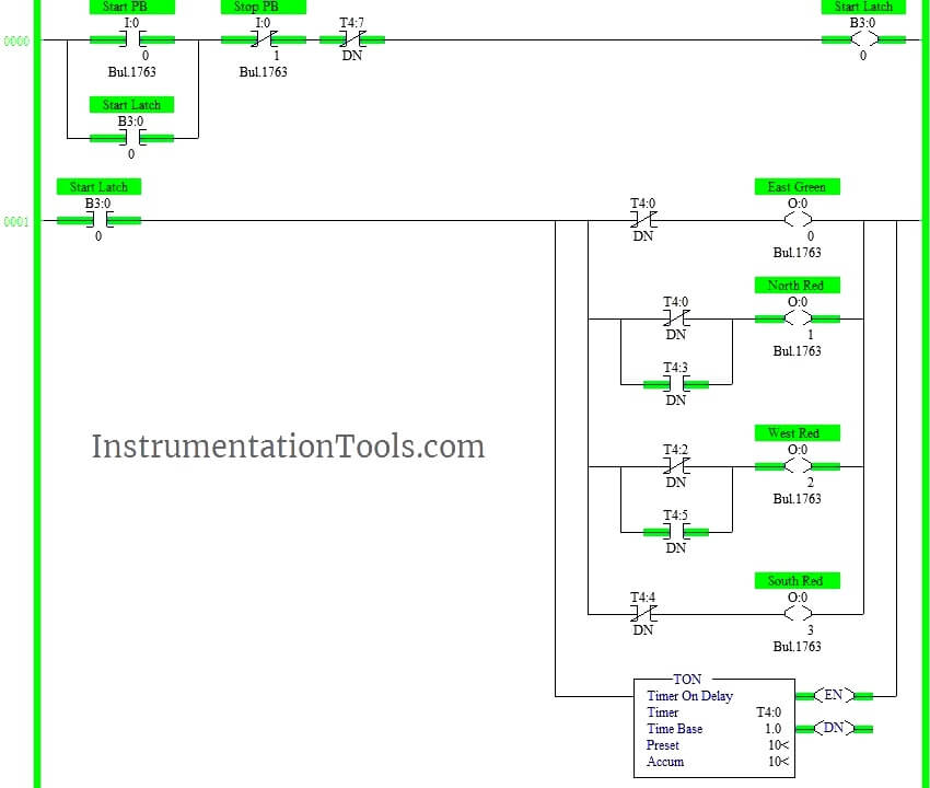
39 plc ladder diagram for traffic light
Now let's have a look at the ladder logic diagram of the PLC based traffic control system. Interlinking all these, let us see how we can actually write a program in PLC. Chapter 8: Ladder Logic Language Reference I. Ladder diagram PLC programming is sometimes referred to as ladder logic.
Understanding the programmable logic controller and its peripherals. Programming the PLC with the STEP 7 software. Applying the PLC to control the operation of a demand-actuated traffic light system in an intersection. Equipments: Table 1. List of Equipments 728 740 Traffic Light Crossing 730 800 PLC Basic Unit
LADSIM uses the PC as a virtual PLC. LADSIM has eight internal simulations; Annunciator, Traffic Light, Car Park, Elevator, Drinks Machine, Packing Line, Bottling Plant, and the ICT3. Logic Diagram Simulator Ladder Logic Simulation software, free download Logic Simulation software, free download 2021

Plc ladder diagram for traffic light
ii. Programmed a ladder logic diagram to control the traffic light. iii. Combine the software part and the hardware part to simulate a traffic light system. 1.5 Problem statement The monitoring and control of city traffic light is becoming a major problem in many countries. The increasing number of vehicles and the lower phase of
CoDeSys is a device-independent PLC-programming system. I already installed the codesys, please say to me: + How to update 2020 year + How to forward date Thank you so much. 3 pentru programare PLC. CoDeSys for Automation Alliance is used by 32 users of Software Informer. Disclaimer This page is not a piece of advice to remove CODESYS V2.
In the circuit diagram only two relays are shown along with the driver circuits consisting of 2n2222 NPN Hands-on PLC programming with RSLogix 500 and LogixPro. • Develop, document, and optimize company software standards (AOI's, PLC coding templates, IPC virtual machines 2. Sc/M. Most of PLC programming software do have simulation mode.
Plc ladder diagram for traffic light.
May 26, 2019 · Most of the PLC programmer works on the ladder diagram programming language. It is pretty easy as compared to other PLC programming languages. How does Programmable Logic Controller Work? The most important working principle is- the PLC is operated by continuously scanning programs. Scanning happens every time per millisecond.
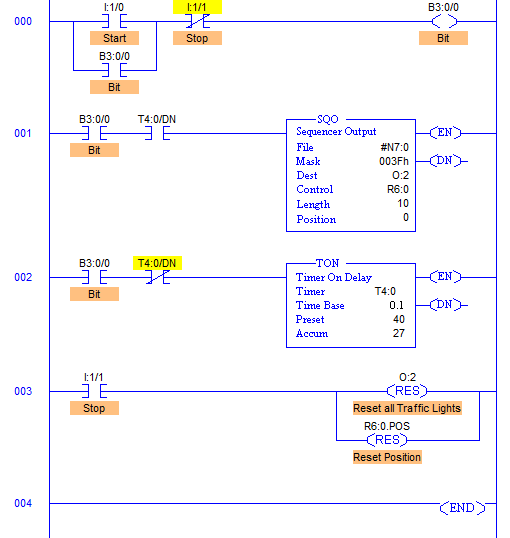
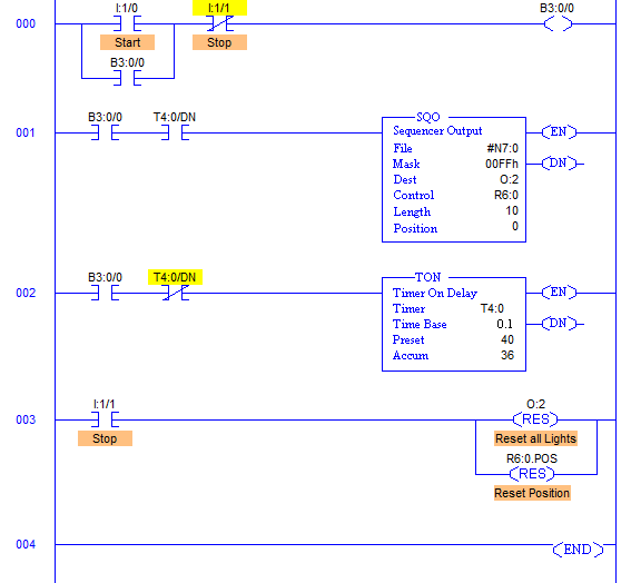
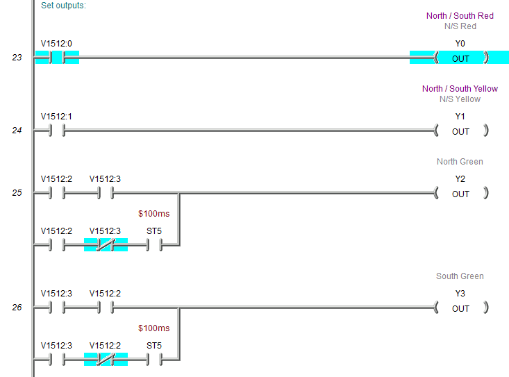
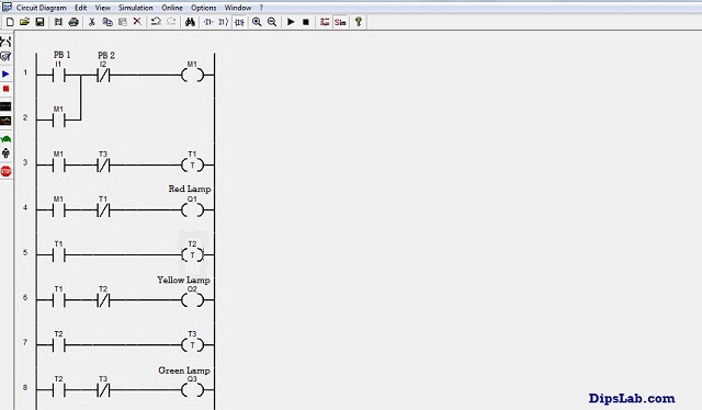
Sep 27, 2019 · PLC based Traffic Light Control System Ladder Logic Diagram: While the switch X0 is turned ON all the lights RED, YELLOW, and GREEN are turned on one by one. This cycle is repeated infinite times until and unless the switch is turned OFF.
Traffic Light: This is a traffic light simulator. In this process animation, you will find a traffic light with 6 outputs. In this process animation, you will find a traffic light with 6 outputs. Enter into the programming window by pressing F5 key and design a Ladder diagram which can simulate this traffic light correctly.
Unit 4 Lab Assignment 7: Ladder Logic Programming for PLC Applications Unit4 Instructor: R. Hakimzadeh Monroe Stockstill I pledge to support the Honor System of ECPI. This article presents an overview of applications of logic programming,classifying them based on the abstractions and implementations of logiclanguages that support the applications.
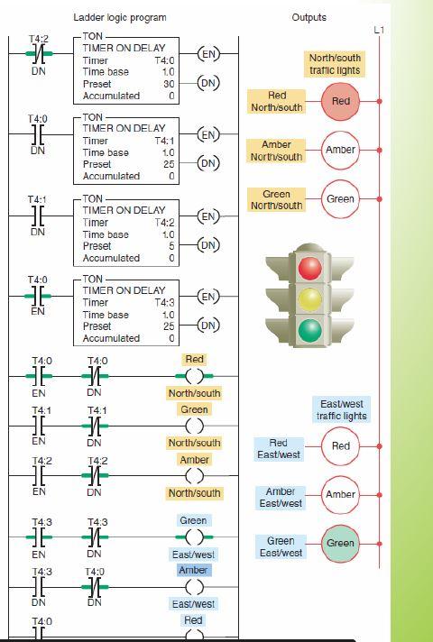
Ladder Diagram or Ladder Logic (LD) Function Block Diagram …Jun 27, 2015 · Traffic Light Ladder Logic Diagram. One of the most used applications for a PLC is the traffic lights. At many schools, universities and even companies you will get the challenge to make a traffic light ladder logic diagram. The traffic light …Nov 05, 2020 · We ...
Design a PLC program and prepare a typical I/O connection diagram and ladder logic program that will correctly execute the industrial control process in Figure 8-38. South African National Department of Basic Education. With the Help of this PDF course You will be able to learn Python Step By Step With Real-time code Examples.
Simple Traffic Light Controller Electronic Schematic Diagram. Traffic lights controller simple four way light circuit sigmatone using 555 timer ic project cd4017 with an arduino schematics com two based 3 signal control led modules let s start 4 complete diagram of the 101 computing implemented on simulator pi my pedestrian tinkercad ics how to build a laptrinhx system program flow chart ...
HVAC UTA - PLC & SCADA Simulatore per unità trattamento aria. The help section can be found on the top menu of the PLC simulator. I'm watting for ur reply. 4: PLC ladder diagram C. Factory I/O 3D PLC Simulator is an impressive software with more than 20 scenes inspired by common industrial applications for real-world control tasks.
Similarly, we will create a ladder diagram for all the gates using the same logic, as discussed above. Ladder Diagram of OR Gate. The ladder diagram of OR Gate is given below: When A = 0 and B = 1, the circuit will appear as: When A = 1 and B = 1, the circuit will appear as: Ladder Diagram of NOT Gate. The ladder diagram of NOT gate is a simple NC.
Analysis to build PLC Ladder logic Diagram program + Demonstration using RS Logix 5000 with Memory c. Plc programming ladder logic online simulator. Example Boolean Equation to ladder logic diagram = (M +11). Today most implementations are done using a specialized microprocessor-based device called a programmable logic controller (PLC).
Arduino traffic light flowchart. Try it out for yourself D. If you have access to an Arduino board you can create your own traffic lights and you can plug your LEDs on a breadboard or use lego bricks to create your traffic lights. 1 x 10k-ohm resistor. Flowchart for traffic light control system. First of we need to build a circuit.
traffic light control using ladder diagram, Mar 10, 2017 · Traffic Light Ladder Logic Diagram; Ladder Diagram for Bottle Filling Plant; PLC Ladder Diagram for Elevator Control; Lets start with basic start and off. Three local teens have been charged in the murder of a 21-year-old Lawrenceville man who was found dead behind a Suwanee home last ...
Ladder Logic Diagram is a symbolic language used in PLC. Block diagram Fig. There is no need for any PLC hardware when using the simulator. This language is covered for Allen-Bradley ControlLogix, CompactLogix, MicroLogix, and SLC-500 processors. The function can be used to start and stop anything like a motor start/stop.
Free PLC Training Software Download : Check out the free PLC lectures, PLC software and example ladder logic programming codes.
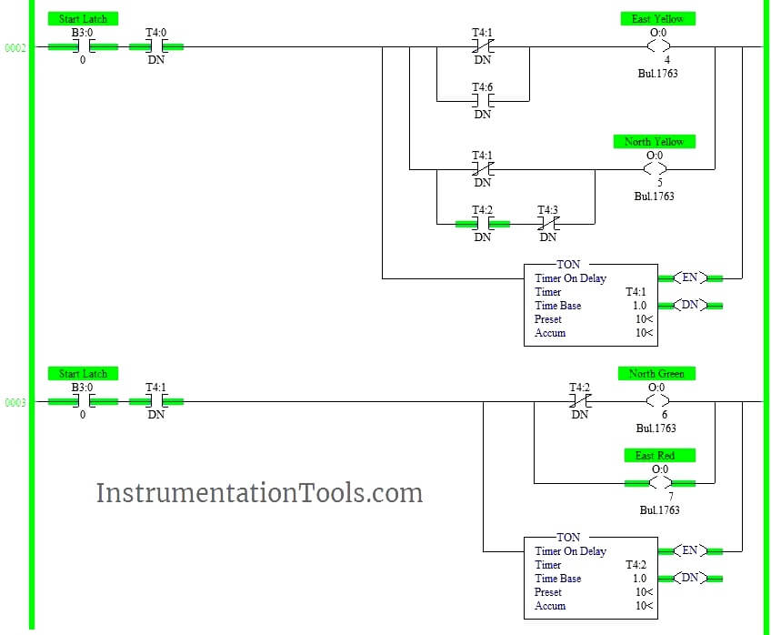
Jun 27, 2015 · Traffic Light Ladder Logic Diagram. One of the most used applications for a PLC is the traffic lights. At many schools, universities and even companies you will get the challenge to make a traffic light ladder logic diagram. The traffic light PLC program is a combination of timers to control which lights are turned on and for how long time.
A plc program like the traffic light is a little more complicated and therefore are a lot more solutions to. In this video you will learn how to make the ladder logic diagram for traffic signal of plc. Plc Ladder Logic Programming Examples With Detailed Explanation from i0.wp.com A program in ladder diagram notation is a circuit diagram that ...
Presentation Topic 4 Way Traffic Lights Ppt. Archaic digital design simple four way traffic light circuit joe s hobby electronics lights tutorial diagram using 555 timer ic 4 implemented on simulation with d flip a system uses logic gates accomplishments christopher mcgill controller sigmatone signal control complete of the simulator question 3 presentation topic an cm 231 two all about ...
Traffic Light Ladder Logic Diagram. This contains seven automata. This application note will not go into the details; it is assumed the user is familiar with setting this. Get Free PLC eBook directly sent to your email, and email subscription to program-plc. An example of discrete (digital) control is: a. (0 - 255) and separated by a dot.
plc programming,plc ladder diagram, plc simulation,and plc training A Programmable Logic Controller is a solid state/computerzied industrial computer that performs discrete or sequential logic in a factory environment. Suggestions for improvement are always. We pride ourselves on helping others learn PLC & HMI automation.
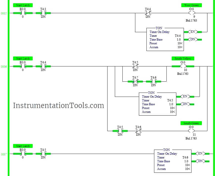
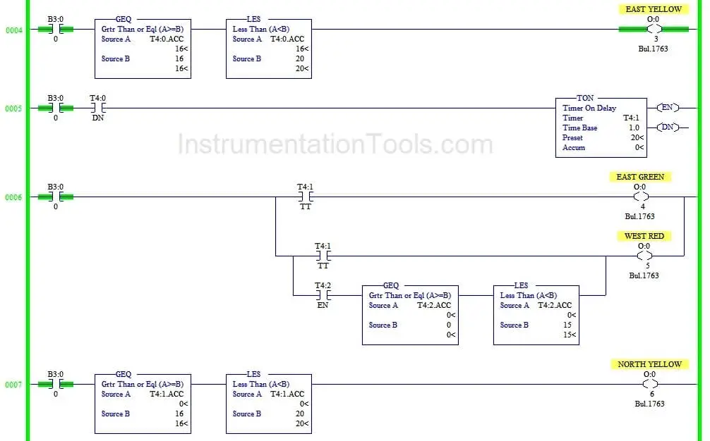
The above explained 4 ways traffic light control using PLC is for example only. It may vary from real time. We can use this example program to understand the working of timers and Interlocking function in AB PLC. Author : Hema Sundaresan. If you liked this article, then please subscribe to our YouTube Channel for PLC and SCADA video tutorials.
[15] light pdf nationzone net, ladder logic examples and plc programming examples, how to write a plc step sequence program control design, traffic light ladder logic diagram using sequence, how to create a ladder logic for 4 way traffic light, experiment 2 traffic light control system for an, lab 10 introduction to ladder logic programming 1 ...
After your training, download one of our FREE PLC software packages from our PLC webpage for hands-on experience with controller programming. The new PLCTrainer version 3 uses RSLogix ladder logic look and feel and now includes analog. Training the HARD SKILLS required to optimize manufacturing performance.













0 Response to "39 plc ladder diagram for traffic light"
Post a Comment