41 ls1 coolant temp sensor wiring diagram
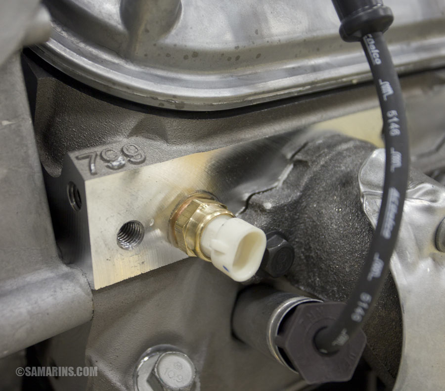
3-wire coolant sensor conversion part numbers - I am not trying to step on any toes, ... Don't all LS engines COME with a 3 wire temp sensor already? Coolant Temperature Sensor Wiring Diagram. On both the v6 4 3 l vortec engine and the 4 8 l 5 3 l and 6 0 l v 8 engines they locate the coolant temperature sensor on the driver side cylinder head. 7 54 throttle position tp sensor 7 69 ambient temperature sensor 7 73 engine coolant level sensor 7 74 oil temperature sensor aw30 40 43 7 76 ...
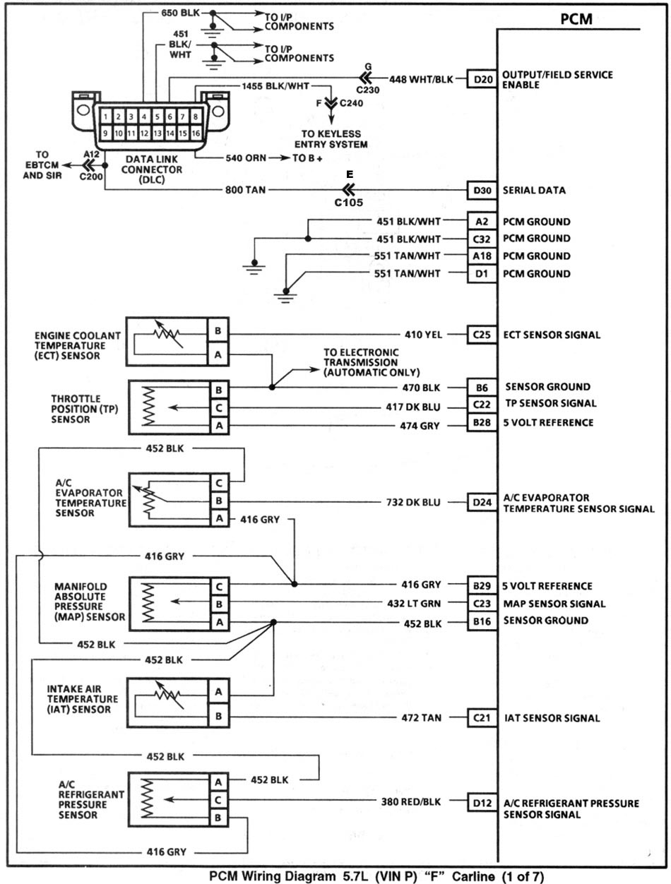
8 Jul 2009 — Im still looking for the coolant temp sensor wires. Does anybody know what is the color codes/ PCM pin numbers? 98 camaro ls1.
Ls1 coolant temp sensor wiring diagram
16 Oct 2006 — Which wires go to the ECM (1 yellow and 1 gray on my 6.0L engine harness) and which wire goes to my temp gauge (green wire for my 93 Yukon)??. Ls1 3 wire coolant temperature temp sensor wiring connector 97 98 gm corvette see more like this. The engine coolant temperature ect sensor is commonly located in either the intake manifold or the cylinder head and measures the temperature of engine coolant. 8 on diagram only genuine oe factory original item. I also drilled a small hole in the thermostat flange. Not only does this help with purging air, it also allows a small amount of coolant flow which I would assume helps the sensor see the correct temperature. For the 5.0, the stock location of the EFI temperature sensor is in the metal tubes for the heater core.
Ls1 coolant temp sensor wiring diagram. Diagram sr20de s14 wiring full version hd quality nissan stereo 200sx service manual sr20det coil pack 35 images question forum forums ls2 truck coils road racing misfire howto p10 p11 sr20ve 29 240sx starter 1990 tail light 1996 in the dash fuse box block circuit breaker carfusebox silvia part 161 into dohc s13 installation specialties harness s14a s15… Read More » 14 Apr 2018 — I followed the steps from LT1swap.com which was very helpful. I have everything wired correctly except the ECT sensor.. using the schematic from ... 22 Jun 2007 — LS1-450 , 06-23-2007 10:58 AM. TECH Junkie. brown top left (ECT ground), yellow top right (ECT signal), gauge wire is bottom center if you ... LT1-LT4 Modifications - Coolant temp sensor - wiring issue? - We replaced my coolant temp sensor which used a 2-wire style pigtail with the new 3-wire style ...
Nov 18, 2020 - Ls1 Engine Wiring Diagram and Ls Engine Controls ... Wiring Diagram For Code 33 - MAP Sensor Circuit (Signal Voltage High - Low Vacuum). Coolant temperature sensor part number 12146312 features design for manufacturability. Ls1 coolant temp sensor wiring diagram. Upgrading to gen iii ls series pcm. For 97 98 ls1 and other gm applications. New pigtail assembly to repair the coolant temperature sensor connector for the listed applications. Ls1 Coolant Temp Sensor Wiring Diagram. The later engines use a two wire sensor and the pcm conditions the signal and a separate signal from the pcm goes to the gauge on the instrument cluster. 8 on diagram only genuine oe factory original item. Sensor Also 1979 Mgb Wiring Diagram On 95 Caprice Lt1 Wiring Harness. The Nissan coolant and oil pressure sensors are required for factory gauge cluster operation. The adapter kit offered by WIRING SPECIALTIES allows the OEM S13/14 coolant temp sensor to thread into the rear passenger head, and the OEM S13/14 oil pressure sensor into the block in the factory GM oil sensor location. The Nissan oil and coolant sensors
Wiring LS1 Fans into 2nd Gen Discussion in 'High ... You want to place the plobe at a place where it can read the temp of cooled coolant. That way if the coolant needs further cooling, the fan speed can be increased or the second fan turned on. ... Hard for me to tell from the description and wiring diagrams they show, but it appears this unit ... Bad coolant temp sensor or ground? help asap. Which coolant temp sensor sends to the gauge?. 4 wire wiring diagram temp sensor diagram base website temp sensor. 035919501 coolant temperature sensor /water temperature sensor for vw,au di,volvo for sale. Oil temp sensor wire diagram. Bmw z3 coolant temperature sensor testing and replacement. 3 pin temperature sensor. this might sound dumb but i was wondering if anybody out there could tell me how i could bypass my 3 wire temp sensor on my 1998 trans am?i dont care about the temp gage not working,would just like to make in run good without flooding itself.theres a car show 6 hours from here that i've been waiting to go to,and my ... 20 Apr 2009 — However the grey wire on the coolant temp sensor was cut. The diagram shows this is supposed to be connected to pin 41 of the computer.
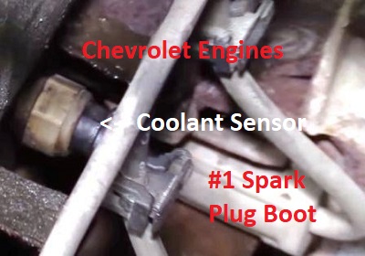
Diagnose Chevrolet Coolant Temperature Sensor Problems
I also drilled a small hole in the thermostat flange. Not only does this help with purging air, it also allows a small amount of coolant flow which I would assume helps the sensor see the correct temperature. For the 5.0, the stock location of the EFI temperature sensor is in the metal tubes for the heater core.
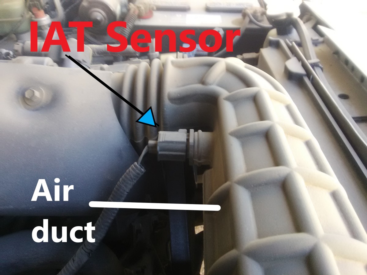
Testing The Intake Air Temperature Sensor Axleaddict
Ls1 3 wire coolant temperature temp sensor wiring connector 97 98 gm corvette see more like this. The engine coolant temperature ect sensor is commonly located in either the intake manifold or the cylinder head and measures the temperature of engine coolant. 8 on diagram only genuine oe factory original item.
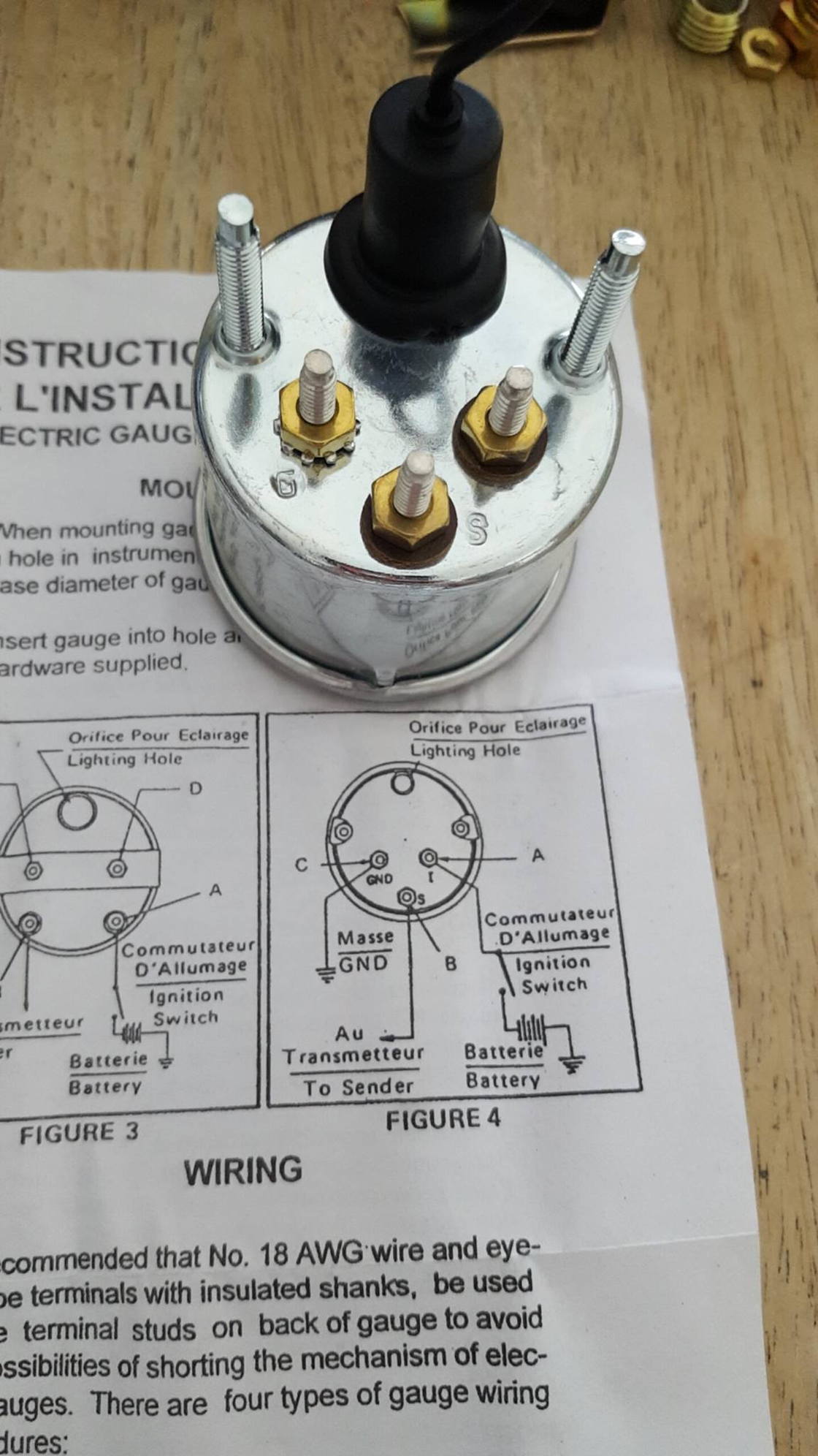
Basic Wiring Water Temp Sensor Gauge Help A Complete Newbie Jeep Cherokee Forum
16 Oct 2006 — Which wires go to the ECM (1 yellow and 1 gray on my 6.0L engine harness) and which wire goes to my temp gauge (green wire for my 93 Yukon)??.
Location Of Coolant Temp Sensor 97 4 6 F150online Forums

Ect Sensor Wiring Diagram Youtube

18 Ls1 Engine Wiring Diagram Engine Diagram Wiringg Net Sensor National Electric Electrical Designer
Coolent Temp Sensor 07 Tb 4 2 Chevy Trailblazer Trailblazer Ss And Gmc Envoy Forum
4th Gen Lt1 F Body Tech Articles

Gm Coolant Sensor 12146312 Interface Sensors Arduino Forum

How Flex Fuel Control Works Haltech

Dohc Engine Swap Finally Modular High Performance Crownvic Net

2001 Ls1 Engine Controls Schematics
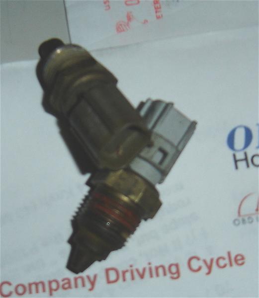
Engine Coolant Temperature Sensor How It Works Symptoms Problems Testing
Stock Ls1 Fan On Temp Settings Third Generation F Body Message Boards
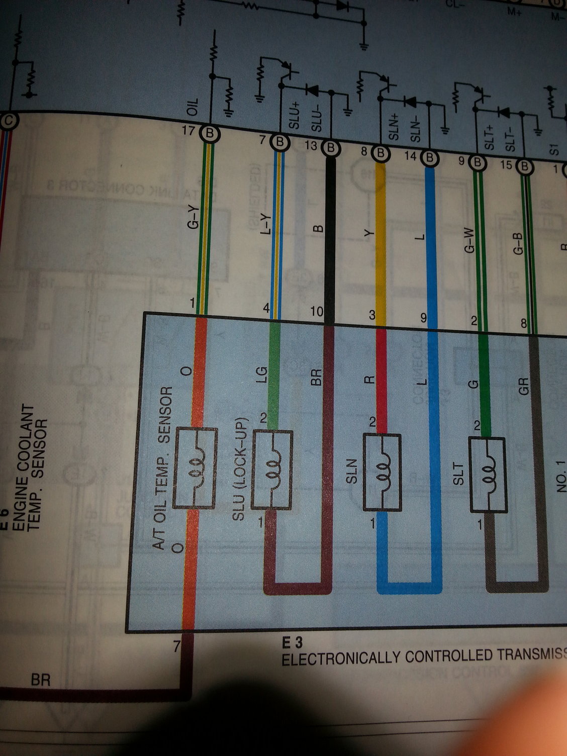
1998 2000 Ls400 Transmission Temperature Sensor Clublexus Lexus Forum Discussion
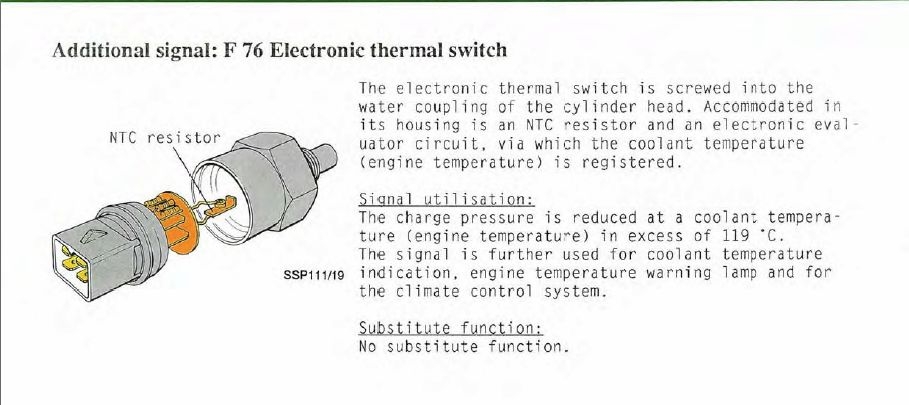
Quattroworld Com Forums F76 Multifunction Temperature Switch R R Info With Cross Links To G62 Coolant Temp Sensor
Toyota 3 Wire Coolant Temperature Sensor Wiring Diagram

Coolant Temperature Sender Third Generation F Body Message Boards

Ls1 Coolant Temp Sensor Wiring Diagram Wiring Site Resource
Correct Temp Sensor Sender For Ls1 Lsx 4 8 5 3 6 0 Obs Swap Youtube
Vw Passat Audi A4 1990 2000 Engine Coolant Temperature Sensor Repair Guide Autozone
Aspen 2007 Durango 2005 2007 Ect Sensor Removal Installation Repair Guide Autozone

Coolant Temperature Sensor Wiring Diagram Wiring Site Resource

Simple Ways To Test A Temperature Sensor With A Multimeter

2001 Ls1 Engine Controls Schematics

Stc 1000 Temp Controller Stilldragon Community Forum Temperature Control Wire Control
Please Help Fj62 Coolant Temp Sensor On 5 3 Ih8mud Forum

Oil Temp Sensor Wire Diagram Corvetteforum Chevrolet Corvette Forum Discussion

Ls1 Coolant Temp Sensor Wiring Diagram Wiring Site Resource

Temp Gauge Not Working S 10 Forum

1998 2000 Ls400 Transmission Temperature Sensor Clublexus Lexus Forum Discussion
Having Cooling Issues For 6 0l Ls1 Swap Third Generation F Body Message Boards

Raspberry Pi Ds18b20 Temperature Sensor Text File
1
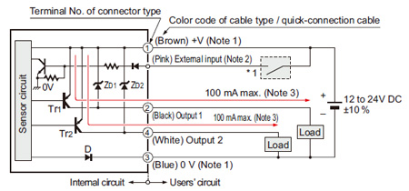
Digital Laser Sensor Ls 400 I O Circuit And Wiring Diagrams Automation Controls Industrial Devices Panasonic

Classic Instruments Sn12mm Water Temperature Sender Gm Ls Engine
Testing The Intake Air Temperature Sensor Axleaddict

Amazon Com Goodeal Coolant Temperature Sensor Connector Repair Pigtail 158 0421 Pmps For Toyota Automotive

Easiest Way How To Run Gauge On Ls Swap With 3 Wire Coolant Temp Sender Youtube
Oil Temp Sensor Wire Diagram Corvetteforum Chevrolet Corvette Forum Discussion
Coolant Temperature Sender Third Generation F Body Message Boards
0 Response to "41 ls1 coolant temp sensor wiring diagram"
Post a Comment