37 consider the circuit in the diagram, with sources of emf listed below
Click here👆to get an answer to your question ️ (10%) Problem 10: Consider the circuit in the diagram, with sources of emf listed below. 5.023 > E2. Randomized Variables & = 28 V E2 = 43 V Ez = 11 V E = 41 V 02 me 400 78 22 TEA W 10.050 h Transcribed image text: Consider the circuit in the diagram, with sources of emf listed below. Randomized Variables_1 = 25 V_2 = 46 V_3 = 15 V_4 = 36 V Find ...
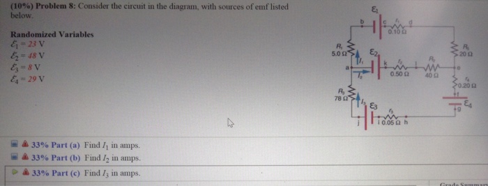
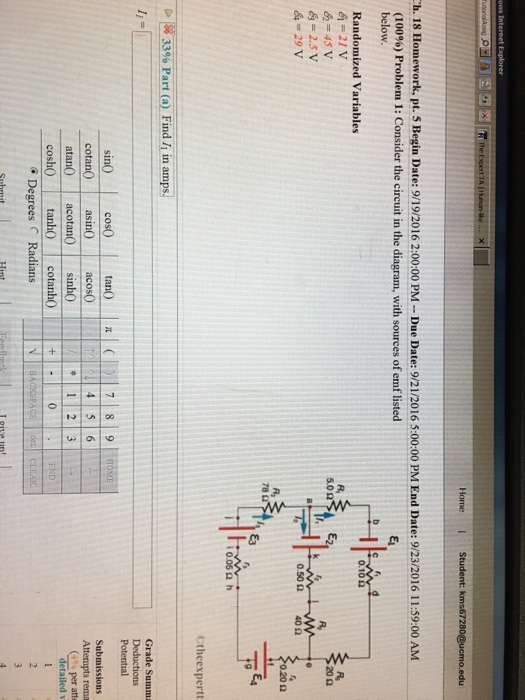
Problem 4: Consider the circuit in the diagram, with sources of emf listed below. Randomized Variables ℰ 1 = 25 V ℰ 2 = 44 V ℰ 3 = 14 V ℰ 4 = 28 V. Part (a) Find I 1 in amps. Numeric: A numeric value is expected and not an expression. I 1 = _____ Part (b) Find I 2 in amps. Numeric: A numeric value is expected and not an expression.
Consider the circuit in the diagram, with sources of emf listed below
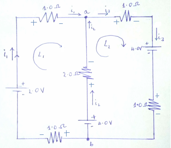
Transcribed image text: Consider the circuit in the diagram, with sources of emf listed below. Randomized Variables_1 = 25 V_2 = 46 V_3 = 15 V_4 = 36 V Part ... Answer to: Consider the circuit in the diagram with in the diagram with sources of emf listed below Randomized variable E 1 = 25 v E 2 = 46v ... The in the with of emf listed randomized variables 6 29 v 502 47 85 45 78 q a. Consider the circuit in the diagram with sources of emf listed below. I know the top one is stronger so the current is traveling in a counter clockwise manner but dont know the technique when there are two emf sources for solving the magnitude of the current.
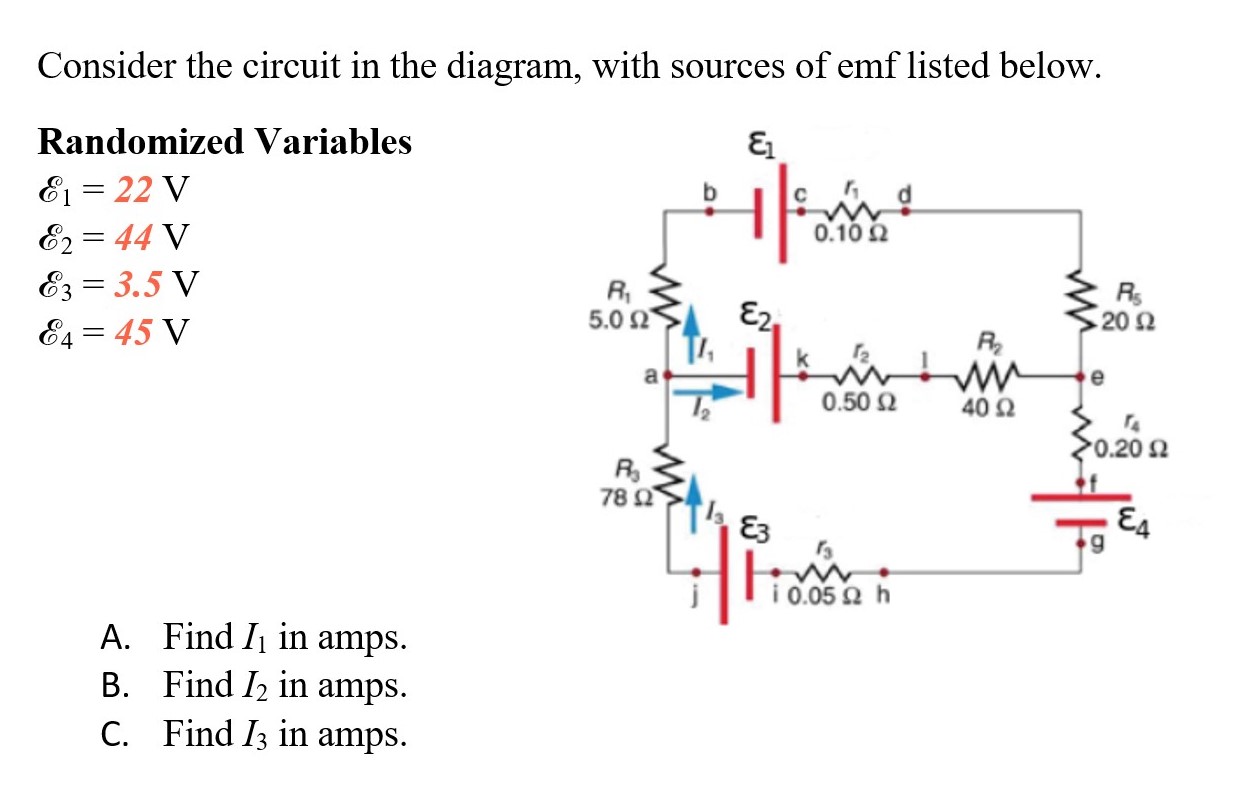
Consider the circuit in the diagram, with sources of emf listed below. Transcribed image text: Consider the circuit in the diagram, with sources of emf listed below. Randomized Variables epsilon_1 = 26 V epsilon_2 = 43 V ... Problem: Consider the circuit in the diagram, with sources of emf listed below.Randomized Variablesℰ1 = 21 Vℰ2 = 49 Vℰ3 = 9.5 Vℰ4 = 39 Va) Find I1 in amps.B) Find I2 in amps.C) Find I3 in amps. Physics Q&A Library Consider the circuit in the diagram, with sources of emf listed below. Randomized Variables E = 22 V Ez = 44 V E3 = 3.5 V 0.10 2 R 5.0 Ω E2 202 E4 = 45 V R a 0.50 2 40 2 0.20 요 R 78 2 E3 i 0.05 2 h A. Find Ij in amps. B. Find I2 in amps. C. Find I3 in amps. Consider the circuit in the diagram with sources of emf listed below. Homework Questions From 10 Print Outs Phy 317l General Physics View the full answer. Consider the circuit in the diagram with sources of emf listed below. C a battery is a good example of a source of emf. 2616 consider the circuit sketched.
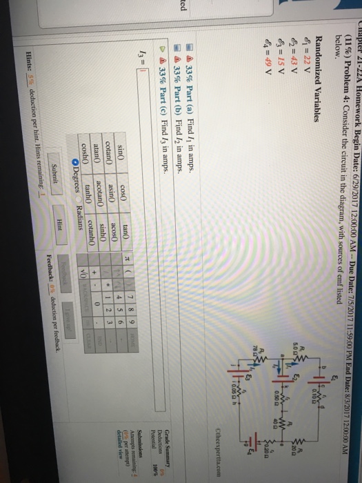
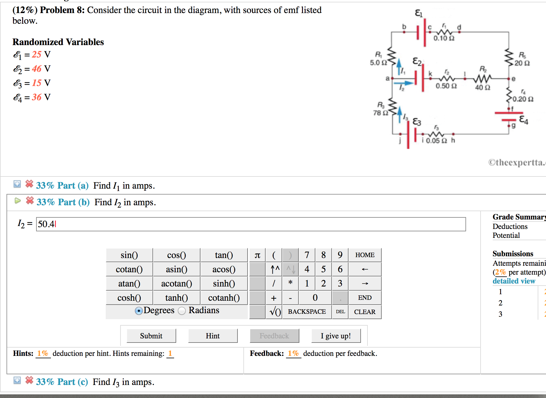
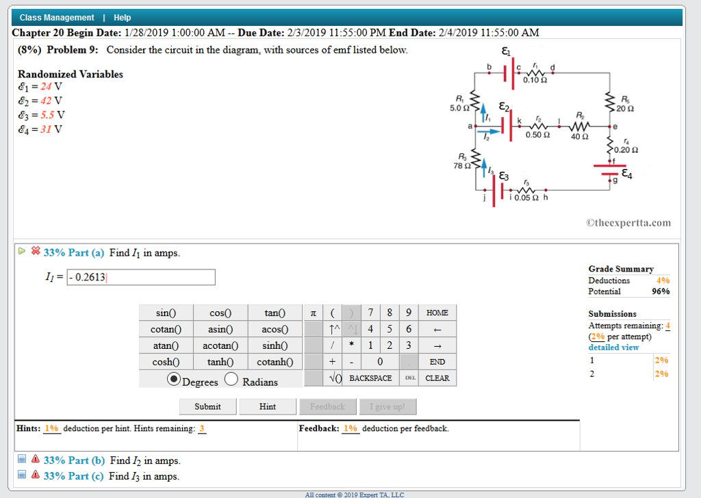
Transcribed image text: (17%) Problem 2: Consider the circuit in the diagram, with sources of emf listed below. Randomized Variables & = 27 V * = 48 V Ez ... Question: "Consider the circuit in the diagram, with sources of emf listed below." Please help, I've been stuck on this problem for a long time now. Question: Consider the circuit in the diagram, with sources of emf listed below. Randomized Variables ℰ1 = 26 V ℰ2 = 44 V ℰ3 = 14.5 ... Question: (9%) Problem 6: Consider the circuit in the diagram, with sources of emf listed below Randomized Variables 81-29 V 0.1 R, 20Ω 83-6.5 V 84-43 V 0.50 Ω 40Ω 020 Ω 78 Ctheexpertta.c Li 33% Part (a) Find 11 in amps. 33% Part (b) Find 12 in amps. 33% Part (c) Find 13 in amps.
Transcribed image text: Consider the circuit in the diagram, with sources of emf listed below. Randomized Variables epsilon_1 = 25 v epsilon_2 = 46 V ... Transcribed image text: Consider the circuit in the diagram, with sources of emf listed below. Randomized Variables epsilon-1 = 22 V epsilon_2 = 49 V ... Consider the circuit in 1 the diagram with sources of emf listed below. With resolution 1637px x 1321px. The circuit diagram below shows two emf sources and a bulb connected in parallel. Randomized variables ac 1 29 v ac 2 41 v ac 3 45 v ac 4 35 v. Consider the two loads in the circuit below load brushless dc bldc motor with arduino part 2 ... The circuit diagram below shows two emf sources and a bulb connected in parallel. Also connected in the circuit is a resistor with resistance R = 0.2? . The ...1 answer · Top answer: I1 = -0.21 A I2 = 0.22 A IS = I1+I2 = 0.01A 270 60.lon LI II Egon ww 1 410 0.son to for 3o. 2o1 L-I 78r 34 13 = (1, +12) CAT 39v 17.50 I o.oor loop ...
2
Answer to: Consider the circuit in the diagram, with sources of emf listed below. Randomized variables: \Epsilon_1 = 22 V, \Epsilon_2 = 49V,...
Sustainability Free Full Text A Review On Battery Modelling Techniques Html
The in the with of emf listed randomized variables 6 29 v 502 47 85 45 78 q a. Consider the circuit in the diagram with sources of emf listed below. I know the top one is stronger so the current is traveling in a counter clockwise manner but dont know the technique when there are two emf sources for solving the magnitude of the current.
Consider The Circuit In The Diagram With Sources Of Emf Listed Below Wiring Site Resource
Answer to: Consider the circuit in the diagram with in the diagram with sources of emf listed below Randomized variable E 1 = 25 v E 2 = 46v ...

Consider The Circuit In The Diagram With Sources Of Emf Listed Below Wiring Site Resource
Transcribed image text: Consider the circuit in the diagram, with sources of emf listed below. Randomized Variables_1 = 25 V_2 = 46 V_3 = 15 V_4 = 36 V Part ...

A Comprehensive Overview Of Power Converter Topologies For Induction Heating Applications Vishnuram 2020 International Transactions On Electrical Energy Systems Wiley Online Library
Consider The Circuit In The Diagram With Sources Of Emf Listed Below Wiring Site Resource
2

Consider The Circuit In The Diagram With Sources Of Emf Listed Below Wiring Site Resource
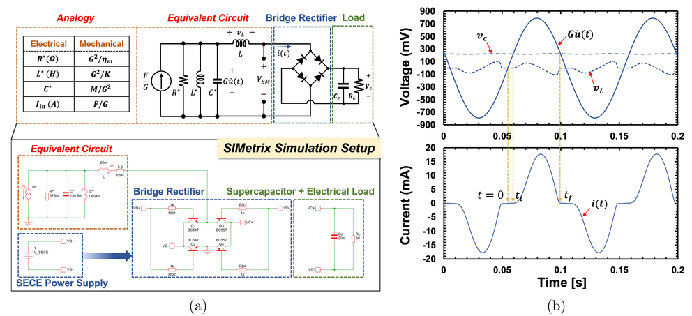
Sshi Based Zero Quiescent Power Control For The Electromagnetic Energy Harvester
2

Twmi9f4c0mpkim

Consider The Circuit In The Diagram With Sources Of Emf Listed Below Randomized Variables Varepsilon 1 29 V Varepsilon 2 41 V Varepsilon 3 4 5 V Varepsilon 4 35 V Study Com

Consider The Circuit In The Diagram With Sources Of Emf Listed Below E1 27v E2 41v E3 7 5v Homeworklib

Experimental Investigation On The Control Strategy Of Split Source Inverter For Grid Connected Wind Power Generation System Nannam 2021 International Journal Of Circuit Theory And Applications Wiley Online Library

Keithley Low Level Measurements Handbook 7th Edition Tektronix

Solved 7 Problem 5 Consider The Circuit In The Diagram Chegg Com
Answered Consider The Circuit In The Diagram Bartleby
Ab 026 Sensorless Speed Stabiliser For A Dc Motor Precision Microdrives

The Circuit Diagram Below Shows Two Emf Sources And A Bulb Connected In Parallel Also Connected Homeworklib
Consider The Circuit In The Diagram With In The Diagram With Sources Of Emf Listed Below Randomized Variable E 1 25 V E 2 46v E 3 15v E

Circuits Rs R Ig Is I R Rs A Chapter 27 R V R E I Ppt Download
3
Solved 12 Problem 8 Consider The Circuit In The Diagram Chegg Com
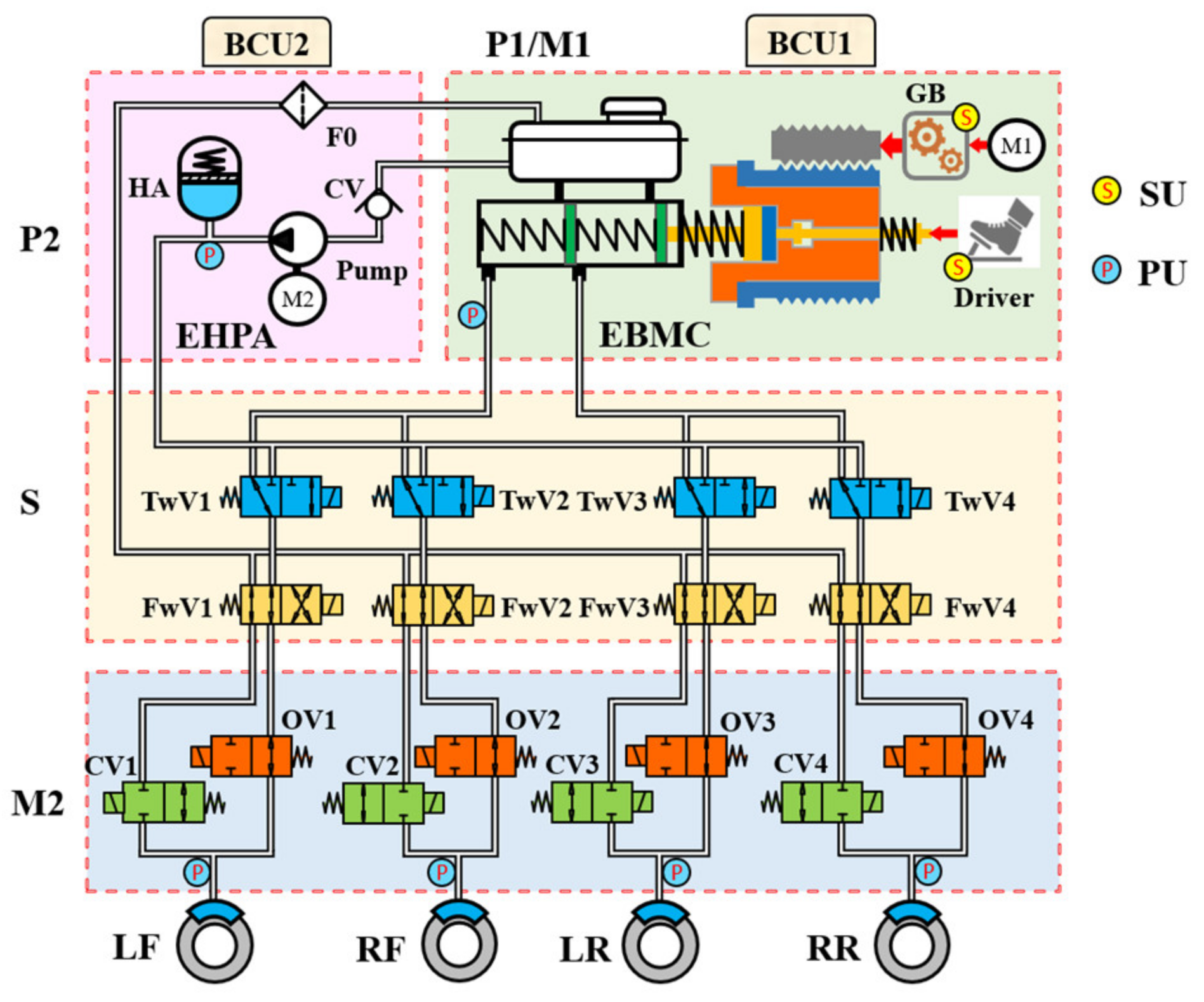
Actuators Free Full Text A Novel Double Redundant Brake By Wire System For High Automation Driving Safety Design Optimization And Experimental Validation Html

Toward Forensic Uses Of Microbial Source Tracking Microbiology Spectrum
2

Consider The Circuit Shown In The Diagram Below For R1 2 Ohms R1 8 Ohms R3 6 Ohms R4 7 Ohms And Epsilon 1 5 V Calculate The Current Through R4 Study Com
Consider The Circuit In The Diagram With Sources Of Emf Listed Atkinsjewelry
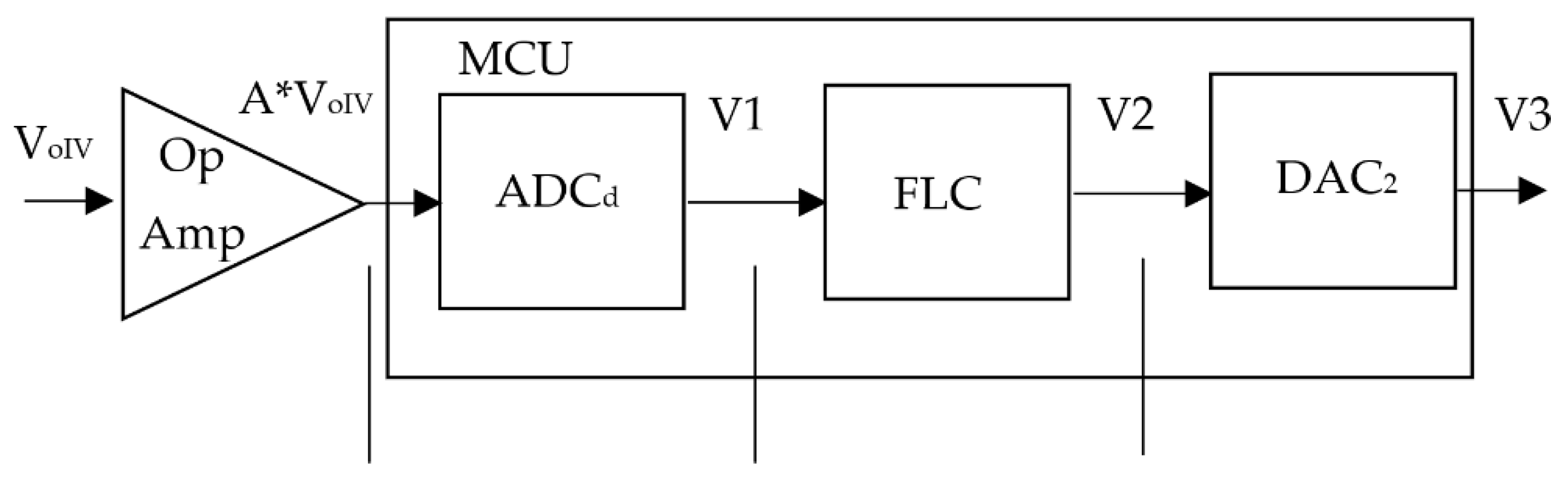
Applied Sciences Free Full Text Measuring Current In A Power Converter Using Fuzzy Automatic Gain Control Html
The Circuit Diagram Below Shows Two Emf So Clutch Prep
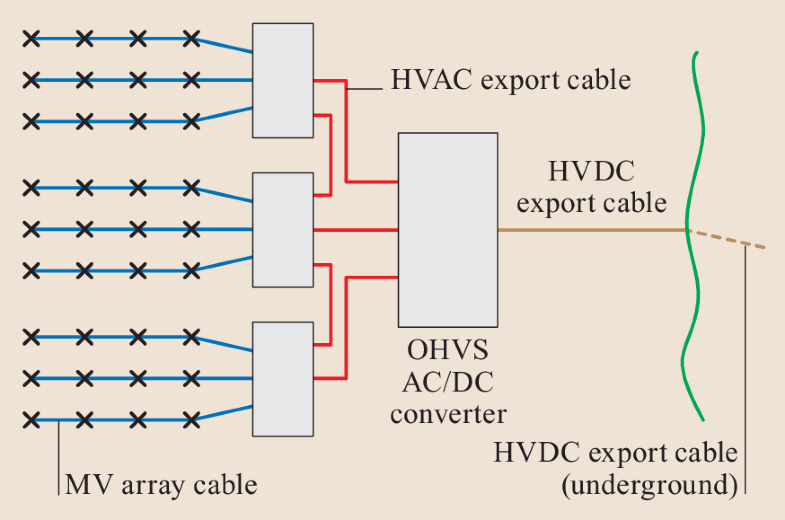
Underground Cables Springerlink

Theoretical And Experimental Investigations On Optimization Of The Received Power Of A Monopole Antenna Iopscience

State Of Charge Estimators Considering Temperature Effect Hysteresis Potential And Thermal Evolution For Lifepo4 Batteries Xie 2018 International Journal Of Energy Research Wiley Online Library
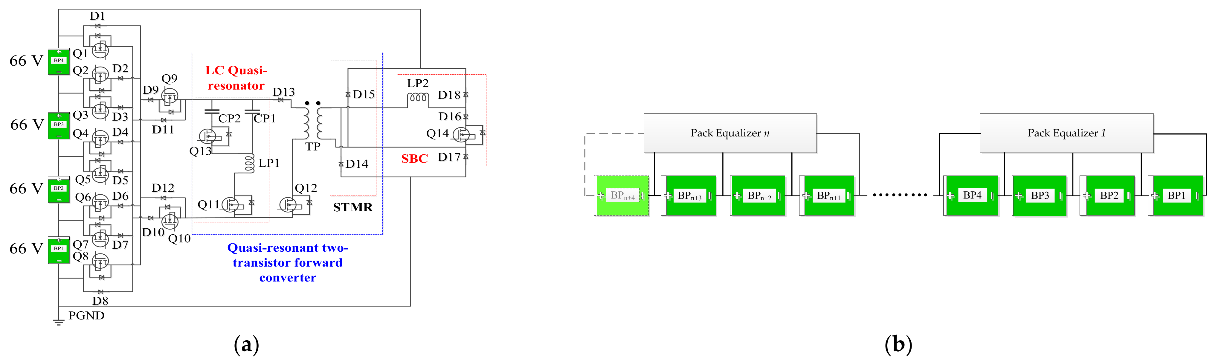
Energies Free Full Text A Bimodal Multichannel Battery Pack Equalizer Based On A Quasi Resonant Two Transistor Forward Converter Html
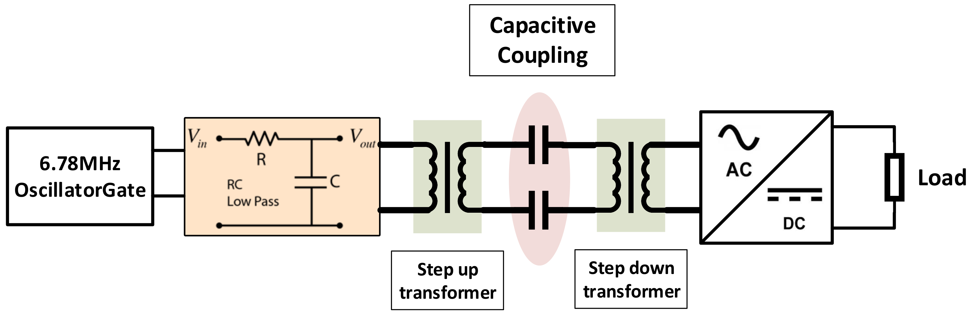
Electronics Free Full Text Electromagnetic Field Based Wpt Technologies For Uavs A Comprehensive Survey Html

Consider The Circuit Shown In The Figure Below Youtube
Solved Consider The Circuit In The Diagram With The Sources Chegg Com
0 Response to "37 consider the circuit in the diagram, with sources of emf listed below"
Post a Comment