40 isolated ground receptacle wiring diagram
Catalog No. NEMA L15-30 Single Receptacle NEMA L15-30 Isolated Ground Single Receptacle NEMA Config NEMA L15-30 NEMA L15-30 Wiring Type Back & side wire Back & side wire Environmental SpecificationsFlammability: Meets UL94 requirements; V0 rated Temperature Rating:-40°C to 60°C (-40°F to 140°F) Flammability: Meets UL94 requirements; V0 rated The Isolated Ground (IG) is a type of equipment ground that, in theory, reduces interference experienced by electronics and instrumentation from radio frequency (RF) noise, by connecting that equipment directly to the grounding terminal of the service equipment, without ever making contact with another metal component or grounded surface, that could potentially be serving as an antenna for ...
Isolated Ground Receptacle Wiring Diagram from i2.wp.com. Print the cabling diagram off and use highlighters to trace the circuit. When you employ your finger or perhaps follow the circuit with your eyes, it is easy to mistrace the circuit. A single trick that I 2 to print exactly the same wiring plan off twice.

Isolated ground receptacle wiring diagram
Isolated Ground Receptacles Service/Branch Panels Surge Protection Receptacles ... Commercial/Industrial Grade,SNAPConnect,Two USB type 2.0 ports 3 Amp 5 V DC, 20A 125V AC,2-Pole 3-Wire Grounding,5-20R,Light Almond. Compare. View Details. Resource Quick View. Section 517.16 in Part II covers receptacles with insulated-grounding terminals and seems to permit isolated ground (IG) receptacles in a general or critical patient care area. The IG receptacles covered in 517.16 consist of a receptacle with the metal yoke of the receptacle isolated from the grounding screw of the receptacle. The neutral wire from the circuit is shared by both sets. A wiring diagram is a simplified traditional photographic depiction of an electric circuit. 3 Wire Plug Wiring Diagram Wiring Diagram Online Receptacle Wiring Diagram. 26052602 - isolated ground receptacle wiring diagram-alt-default created date.
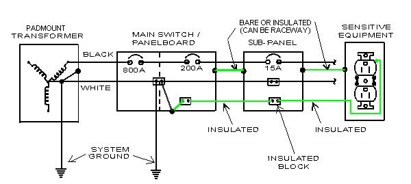
Isolated ground receptacle wiring diagram. Isolated Ground Receptacle Wiring Diagram - wiring diagram is a simplified gratifying pictorial representation of an electrical circuit. It shows the components of the circuit as simplified shapes, and the power and signal connections amid the devices. A wiring diagram usually gives counsel roughly the relative approach and conformity of ... 15 or 20a, 125v quadruplex receptacle, w/ isolated ground flush wall mounted @ 18" aff, uon number indicates quantities of ig type receptacles. 1 = one duplex ig type & one duplex standard g. receptacle 2 = quadruplex ig type receptacles junction box mounted above suspended ceiling / flush wall installed within 2' of equipment and connected 26052602 - Isolated Ground Receptacle Wiring Diagram-alt: March 2014: PDF: Microstation: AutoCAD: 26052603 - Transformer Pad Grounding Detail-alt: March 2014: PDF: ... 26200001 - Service Entrance Transformer Wiring Diagram: April 2014: PDF: Microstation: AutoCAD: 26200002 - Step Down Transformer Wiring Diagram: August 2020: PDF: A basic diagram of this type of improper wiring can be seen below, where a separately driven ground rod is used to reference the insulated equipment grounding bus in a sub-panel. In 1984, responding to this and other incidents, the authors of the National Electrical Code provided installation requirements for an isolated equipment grounding ...
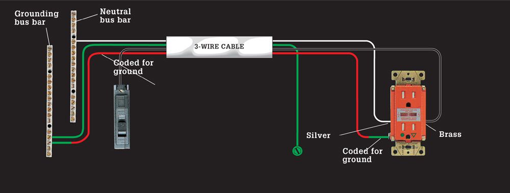
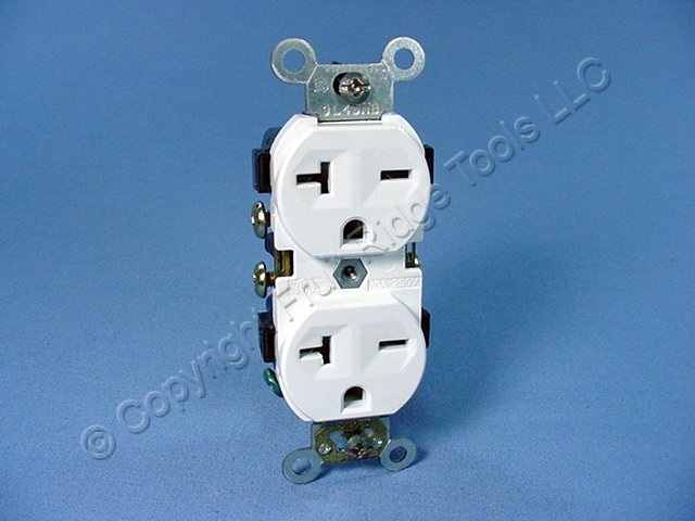
The isolated grounding wire connects to the isolated ground bar in the panelboard. The isolated grounding conductor will be fastened to only the isolated grounding terminal of the isolated ground receptacle. It shall not make electrical contact to any conduit, "j"-box or any other item in contact to the common ground. The Pros and Cons of IG Wiring. Nov. 1, 2007. Confusion continues to surround the use, performance, and NEC requirements of isolated ground (IG) wiring. Can it be used anywhere, or is it restricted to electronic load equipment? Does it really reduce electrical noise? What does the Code say about IG wiring? These are the questions we'll address ... Visit http://www.MikeHolt.com/code to explore our product catalog. Mike Holt Enterprises offers comprehensive electrical training materials delivered in a lo... Isolated ground receptacles have special construction and wiring that help eliminate electromagnetic "noise" that can affect sensitive electronic equipment. They are very rarely installed in homes but sometimes are used in large installations to combat noise interference with audio, video, and computer equipment.
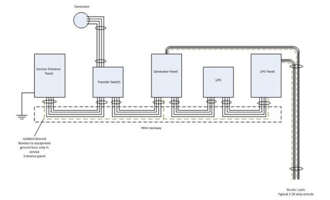
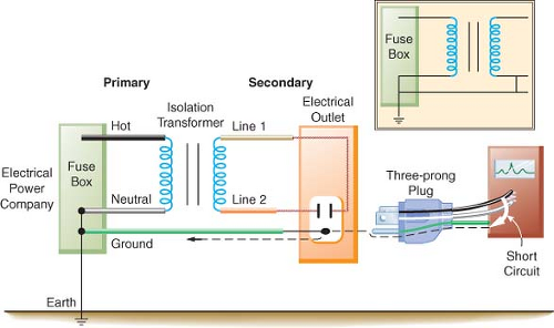
• A green LED remains lit when the system is adequately isolated from ground. ... Wiring Diagram L1 L2 12 Vdc Com A B RI1 K1/NC K1/COM K1/NO SAFE HAZARD RI2 GND2 LIM GND ... Panel ground Panel ground Panel ground Incoming power H2 H1 X2 X1 L1 L2 To system ground Receptacles and ground jacks are options. 16 14 12 10 8 6 4 2 15 13 11 9 7 5 3 1 ... Isolated Ground. from. vimeo. ·. A brief overview of how an isolated ground outlet is wired, compared to a standard outlet. Diagram is from Middle Atlantic's power and grounding white paper.…. Vimeo. 184k followers. More information. Hospital Isolated Power Systems Class 4800 CONTENTS Description Page General Information and Application ... Isolated Ground Receptacle Wiring Diagram - Gooddy, size: 800 x 600 px, source: gooddy.org How To Extend Power From An Existing Wall Outlet With Wiremold, size: 800 x 600 px, source: www.handymanhowto.com
Wiring Gfci Outlet Diagram Cleaver Three Prong Plug Wiring ...
isolated gnd bus equipment gnd bus ground bus neutral bus 208/120v bus neutral l n iso. gnd ground (equipment) enclosure ig receptacle (if used) main breaker receptacle panel no scale receptacle wiring diagram isolated ground 26052602.dgn. title: 26052602 - isolated ground receptacle wiring diagram-alt-default

Wiring Diagram Isolated Ground Receptacle - Circuit ...
http://www.theaudiopedia.com What is ISOLATED GROUND? What does ISOLATED GROUND mean? ISOLATED GROUND meaning - ISOLATED GROUND definition - ISOLA...

Step into the life of bobby the ant. See what he sees. Life is beautiful down there, isn’t she ?
Description Industrial Grade Isolated Ground Duplex Receptacles AC Horsepower Rating At Rated Voltage 1 HP Electrical Specifications Amperage 15A or 20A Voltage 125VAC NEMA 5-15R or 5-20R Grounding Isolated ground Pole 2 Wire 3 Dieelectric Voltage Withstands 1250VAC per UL 943 and CSA-C22.2 No. 144.1-06 Short Circuit Current Rating 10kA
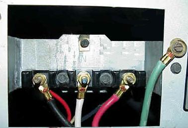
Wire a Dryer Cord
2320-IG. Roll over to zoom. 20 Amp, 250 Volt, NEMA L6-20R, 2P, 3W, Flush Mtg Locking Receptacle, Industrial Grade, Isolated Ground, V-0-MAX - ORANGE. Leviton's Industrial Grade Locking Devices are built to provide unparalleled quality and superior performance in the most severe industrial settings. Leviton combines the best materials ...

Demystifying the Neutral-to-Ground Connection ...
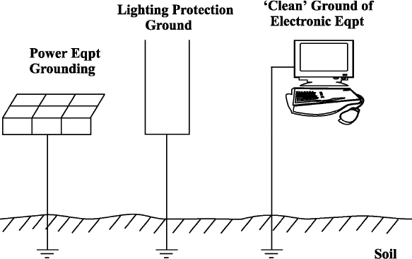
Isolated Ground Isolated grounded receptacle has an isolated terminal from the yoke to the ground Lug. These receptacle are usually marked with an orange triangle or all orange. Sub Panel Ground Bus Neutral Bus. Floating Ground zThe neutral on a wye system is not intentionally grounded

Diagram 110V Plug Wiring Colors Database
Isolated Ground. 8 years ago. Craig Underwood. A brief overview of how an isolated ground outlet is wired, compared to a standard outlet. Diagram is from Middle Atlantic's power and grounding white paper. It's available at middleatlantic.com.

31 Common Household Circuit Wirings You Can Use For Your ...
An isolated ground receptacle (IGR) can reduce electrical noise, but if installed incorrectly, it can create a dangerous installation. This receptacle differs in construction from its self-grounding counterpart. The grounding terminal for an IGR is insulated from its metal mounting yoke. This means you must connect the grounding terminal directly to an effective fault current path by an insulated
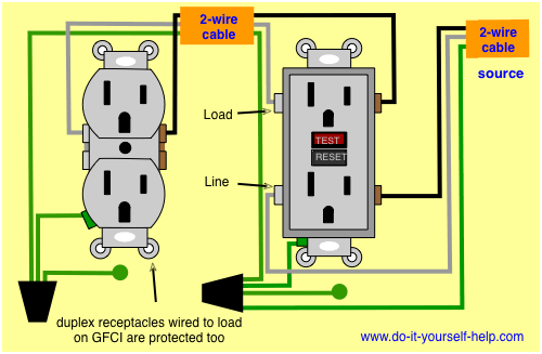
Wiring Diagrams for Electrical Receptacle Outlets - Do-it ...
When a design calls for an isolated grounding receptacle and circuit to be installed in a patient care area, the branch circuit must not only meet the requirements for two equipment grounding conductors as called for in 517.13, but must include a third insulated equipment grounding conductor that meets the rules in 250.146 (D) and 406.2 (D ...
The Isolated Ground - Engineering Radio
Patented feature, external screw-pressure-plate back wire clamp on ground terminal for faster, easier installation. Plastic barrier isolates grounding terminal from mounting strap and metal boxes. Side and internal screw-pressure-plate back wire capability with #14 - #10 AWG copper or copper-clad, solid or stranded wire.

Wiring Diagram Isolated Ground Receptacle - yaseminergene.net
An isolated ground provides for the benefits of star single point equipment grounding in an environment with multiply connected equipment grounding paths. As such, a _radial_ circuit wired using non-metallic cable to a non-metallic box using a normal receptacle _is_ an isolated ground receptacle.

Electrical Panel "cut-in" Question - Electrical - Page 2 ...
Sep 9, 2016 - Clear, easy-to-read wiring diagrams and instructions for household circuit breakers including: a breaker panel box, 15amp, 20amp, 30amp, 50amp, and gfci breakers.

A Walk In Your Shoes
The neutral wire from the circuit is shared by both sets. A wiring diagram is a simplified traditional photographic depiction of an electric circuit. 3 Wire Plug Wiring Diagram Wiring Diagram Online Receptacle Wiring Diagram. 26052602 - isolated ground receptacle wiring diagram-alt-default created date.

Christ Church Burial Ground
Section 517.16 in Part II covers receptacles with insulated-grounding terminals and seems to permit isolated ground (IG) receptacles in a general or critical patient care area. The IG receptacles covered in 517.16 consist of a receptacle with the metal yoke of the receptacle isolated from the grounding screw of the receptacle.
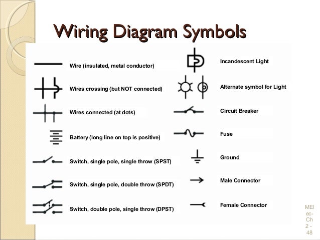
Electrical Wiring Practices and Diagrams
Isolated Ground Receptacles Service/Branch Panels Surge Protection Receptacles ... Commercial/Industrial Grade,SNAPConnect,Two USB type 2.0 ports 3 Amp 5 V DC, 20A 125V AC,2-Pole 3-Wire Grounding,5-20R,Light Almond. Compare. View Details. Resource Quick View.

Wiring Diagram Isolated Ground Receptacle - Circuit ...
Electrical and Fire Safety* | Anesthesia Key
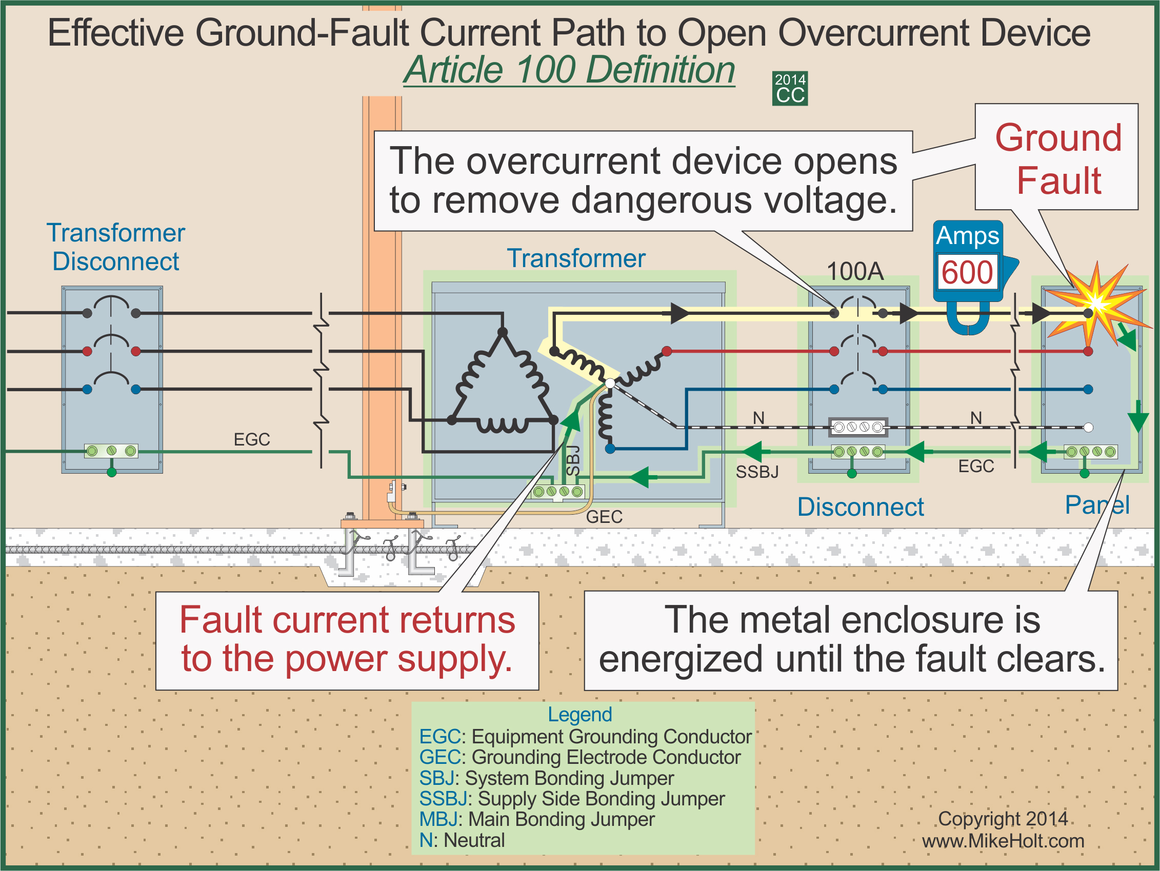
Mike Holt Code & Safety - 2014 Understanding the National ...
CLIFF Electronic Components - Dual USB Connectors in XLR ...

Isolated Ground Wiring Diagram Receptacle - DALEACA
31 Common Household Circuit Wirings You Can Use For Your ...

Electrical Outlet Ground Connection Brilliant Best Wiring ...

Wiring a Room Addition - Home Wiring - Green Building Central
Isolated Ground Wiring Diagram Receptacle
How does earthing help to prevent electric shocks? - Quora
my last ELECTRICAL question - Page 14 - The Hull Truth ...

Wiring a Room Addition - Home Wiring - Green Building Central
Circuit Maps - The Complete Guide to Wiring - Black ...

Wiring Diagram Isolated Ground Receptacle - Circuit ...

NIH Standard CAD Details
Electrical and Fire Safety* | Anesthesia Key
voltage - Help me understand the relationship between ...

Electrical Outlet Installation Details Best Switch Outlet ...
Nema 6-20r Receptacle Wiring

ELECTRICAL ABBREVIATIONS | | AutoCAD Free CAD Block ...
![[DIAGRAM] 4 Ground Wiring Diagram PDF Download - Pascol](https://lt1swap.com/pictures/isolated_ground_schematic.gif)
[DIAGRAM] 4 Ground Wiring Diagram PDF Download - Pascol

Isolated Ground Receptacle Wiring Diagram - Wiring Diagram
_OrangeTriangleOutletReceptacleNEC_250.146dException_4_EMI_NoiseReductionNEC_256ObjectionalCurrent.jpg)
Wiring Diagram Isolated Ground Receptacle - Circuit ...
ISOLATED GROUND - ECN Electrical Forums

Subpanel Wiring Help - Electrical - DIY Chatroom Home ...

can ground and neutral be double taped at panel
0 Response to "40 isolated ground receptacle wiring diagram"
Post a Comment