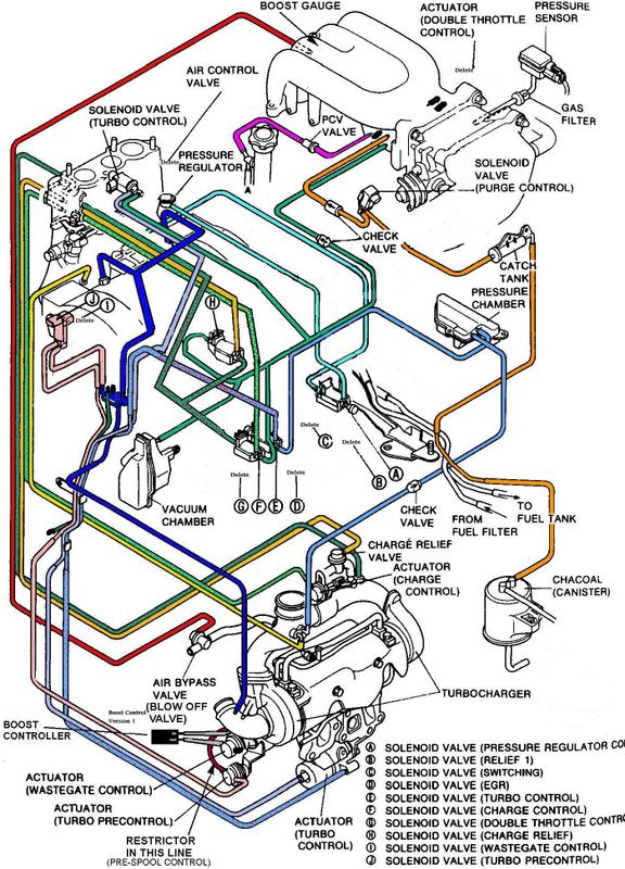
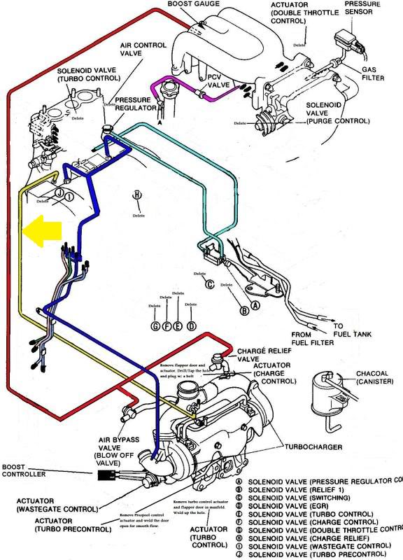
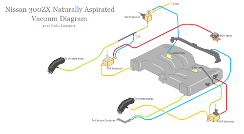
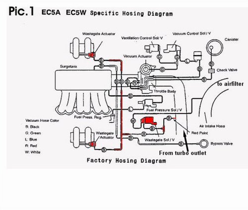
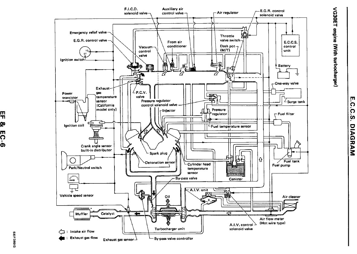
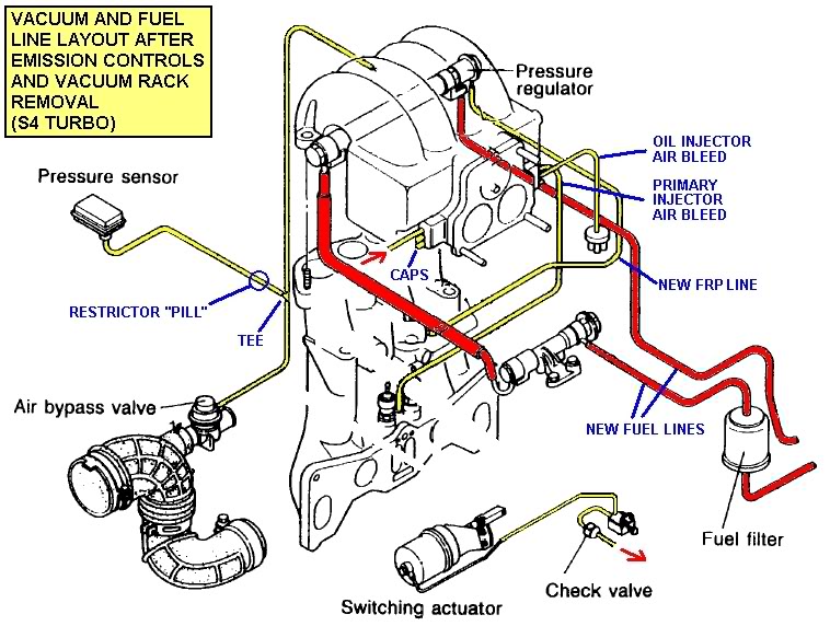
39 turbo vacuum line diagram
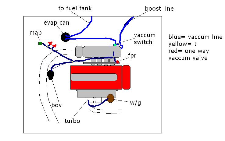
86/87 vacuumhosekit. Vacuum Hose Kit 86 - 87 944 Turbo. Starting from: $347.60. More Info >. Starting from: $347.60. Add to Cart. 32. skukey_1144178174. 944 Turbo Intake Boot Clamp Kit. 93 Legend L Coupe. It's a decent diagram, but I don't care for one thing: the wastegate line shouldn't be running that far. If you tap the wastegate line closer to the turbo, you will have better boost control and throttle response. Running feet of vacuum hose inscreases the mass of air that has to be moved in order to move the wastegate diaphram.
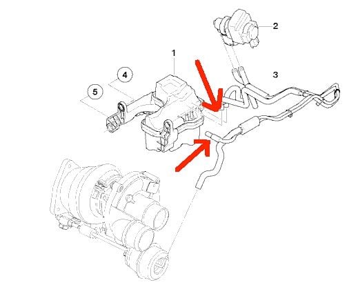
I am trying to clarify how my [our] car's turbo vacuum lines are run vs how they should be. I have found some parts diagrams across the web, but would prefer to get details from someone first hand. Can someone(s) with a bone stock n54 335i confirm that this diagram is the proper factory...
Turbo vacuum line diagram
Turbo Waste Gate Solenoid Boost Pressure Vacuum Lines Connection Routing. When you are connecting the vacuum lines to/from your turbo, there's a few different ways to do it, depending on what else you have connected to the turbocharger. Waste gate, solenoids, etc., will determine how you go about accomplishing this task. Feb 28, · SRT-4 vac line set up is this the proper way to set them up on stock turbo stock blow off valve with blue rice plate. Factory Vacuum line diagram for Dodge SRT July 13, MP Blog admin. We've had a lot of customers call and ask how the factory vacuum line should run on their Neon SRT-4's. HOW TO RUN VACUUM LINES FOR WASTEGATE & BLOW OFF VALVEPayPal Donate https://paypal.me/duwop77?locale.x=en_UST-Shirts-https://teespring.com/stores/duwop77-3In...
Turbo vacuum line diagram. Volvo 850 Turbo - TCV / Vacuum hoses diagram. This is the correct Vacuum hoses routing for the Volvo 850 TCV (Turbo Control Valve). The vacuum hoses for the TCV are the first cause of failure when you have boost issues, both lacking boost and overboost. When replacing the hoses make sure to re-connect them like in the diagram above. Wiring & Vacuum Diagrams...and much more!! This product includes - Colorized wiring diagrams - Vacuum diagrams - Vol. III 1972 Car Shop Manual, Electrical - Electrical Illustrations - How to Read Wiring Diagrams training course 5236 Licensed and approved by the Ford Motor Company 1972 Free Bonus! 30-Minute Video Ford Training Course 13001, Vol ... Volvo 850 Vacuum Hose Diagram. This is for a '98 T-5. Others will vary but the same or similar to most 850 turbo's. The designed changed with later S/V/70's so be aware. I got so darned frustrated trying to see this intsy bittsy diagram under the hood of the car, so I finally took a decent digital picture today. turbo vacuum line help. Im in need of a diagram or something to direct me on where the vacuum lines and boost lines go. If anyone can help that'd be appreciated. I'm not hitting any boost right now cause they're All mixed up * Registered users of the site do not see these ads.
Specs- 350 engine, Edelbrock Performer EPS manifold, Holley 4160, TH350 trans (rebuilt w/shift kit), 3.73 posi. I stopped at the transmission place that rebuilt my transmission about a year ago. They looked at it and said the vacuum line should be connected to a vacuum port directly on the manifold, ie. the same one that the brake power booster ... Vacuum Line Routing for 231 3.8 Liter Turbo. Here's a handy schematic of how the vacuum lines get routed on the 3.8 liter turbocharged motor found in 1986-1987 Buick Turbo Regals. . . Related Stuff: vacuum line sizes. wastegate/boost controller vacuum lines. . Tags: 1986 1987 231 3.8 vacuum line. motogurumag.com is an online resource with guides & diagrams for all kinds of vehicles. If you look for a fuse box diagram, timing belt diagram, or maybe wiring diagram - this is a place for you. We also have over 350 guides & DIY articles about cars. C O M. Below is a collection of Volvo vacuum connection diagrams I have located or (some) created from Volvo service manuals and other sources. I'm always looking for more diagrams to help our fellow Volvo owners who are having a tough time locating these. Under Hood Vacuum Label Collection here. If you can help supply more Volvo vacuum ...
Factory Vacuum line diagram for 2003-2005 Dodge SRT-4 by Modern Performance July 13, 2010, 1:08 pm 4.8k Views We've had a lot of customers call and ask how the factory vacuum line should run on their Neon SRT-4's. Vacuum lines dry out and crack over time. Often they are routed under the intake and/or close to HOT exhaust. Here is a quick tip that can help you route t... So I have an update. I spent some time tracing the vacuum hose routing in the car, and comparing it to the VW Vacuum Hose Routing Diagram. In my first post I mentioned a 'stray' hose that was disconnected, and as it turns out the hose is not on the diagram. On closer inspection, it originates from a T-Piece in the N75 to VNT Actuator Line. VACUUM DIAGRAMS 944 TURBO One of the most common problems we find with the 944 Turbo is vacuum line related, whether it's old and leaking hoses, or mistakes in the plumbing of your updated vacuum lines. We have Vacuum Hose Kits to replace those old lines and recommend doing so. Below are several diagrams that should aid you in the correct ...
FUEL-15, Fuel and Vacuum Line Diagram (944 Turbo) Acrobat Printable Version Introduction. The following fuel system line diagram includes most of the vacuum line routing for 944 Turbos. If the vehicle is equipped with an active carbon tank for fuel tank venting, there will be additional vacuum line routing for that system.
I have checked out the vacuum line routing HOW TO's but they are still unclear as to how the brake booster is hooked up. mods : external wastegate 38mm big turbo turbo xs rfl bov agp fuel return No solenoids I have some questions but its probably easier to just post a diagram of what I have so far. Any suggestions would be great.
Hey guys, I decided to put together a reference guide to replacing the vacuum hoses on the 35d models. I haven't had the time to put together a full DIY guide but this one at least gives you an idea as to the parts needed and I also included some of the diagrams for quick reference. If you have any questions please feel free to post here or PM me.
On3 turbo vacuum lines. Jump to Latest Follow 1 - 8 of 8 Posts. S ... The diagram helps a lot, but what if my compressor housing does not have a tap to run a vacuum line to it? Should I tap it myself? Save Share. Reply. S. snakeeyesmustang302 ...
Vw 1 8t vacuum diagram furthermore watch also 1 8t wastegate location as well as watch as well as audi tt engine diagram in addition volkswagen sharan 2 0 specs and images along with 19 further vw passat 1 8 t engine diagram graphics also need 01 1 8t awm vaccum line diagram also vw 1 8t engine codes also 04 vw jetta 1 8t engine diagram along ...
MINI factory OEM replacement Vacuum Line to the Turbocharger. Fits the following Cooper S models with the N14 engine: 2007-2010 R56 MINI Cooper S Hardtop 2008-2010 R55 MINI Cooper S Clubman 2009-2010 R57 MINI Cooper S Convertible. Also compatible on JCW models with the N14 engine (2008-2012). For a complete listing of Turbo related parts, click ...
Vacuum Diagrams This is not an automated service. Each Diagram that is requested has to be hand selected and sent. As this is a free service it receives an overwhelming amount of requests and may take up to a week or longer for a response.
Joined Jan 9, 2006. ·. 132 Posts. #5 · Nov 16, 2015. So I converted my top end to use an STI intake manifold, STI TMIC, and STI style turbo because.... well just because! Actually I had done the same thing on my 2005 Outback XT which has the same engine layout as the 09+ Foresters and I wanted to reuse my Bluch 20g turbo.
Is there a diagram that shows how the vacuum lines hook up for the 2.5 Turbo ? Vacuum hose routing-1989 2.5L California Turbo I engine Vacuum hose routing-1990-91 2.2L and 2.5L Federal engines with manual transaxles, and 2.2L and 2.5L Canadian and California engines

I Need A Diagram Of The Vacuum Lines From The Turbo And Intercooler And Where They Go 1988 Ford Thunderbird 2 3 Turbo
FINALLY, a Vacuum Hose Diagram Topic is solved. This is for a '98 T-5. Others will vary but the same or similar to most 850 turbo's. The designed changed with later S/V/70's so be aware. I got so darned frustrated trying to see this intsy bittsy diagram under the hood of the car, so I finally took a decent digital picture today.
from throwing CEL and plug the port of the evaporative. canister hose on the turbo inlet hose after you remove the. canister. The boost gauge may be ran off the "P"port of the. throttle body or the FPS line. Also found the diagrams for the 1g-. 1g Before and normal vacuum wiring:
the vacuum reservoir ball connects to the other leg of the HVAC check valve by the firewall , it also has a y fitting inline by the horn for the feed to the cruise control servo (plugged at one end of y if non cruise) you cant just connect the ball any where as its function is only to provide vacuum to the hvac to operate the hvac doors/heater ...
HOW TO RUN VACUUM LINES FOR WASTEGATE & BLOW OFF VALVEPayPal Donate https://paypal.me/duwop77?locale.x=en_UST-Shirts-https://teespring.com/stores/duwop77-3In...
Feb 28, · SRT-4 vac line set up is this the proper way to set them up on stock turbo stock blow off valve with blue rice plate. Factory Vacuum line diagram for Dodge SRT July 13, MP Blog admin. We've had a lot of customers call and ask how the factory vacuum line should run on their Neon SRT-4's.

Amazon Com Bmw Mini Genuine Turbocharger Vacuum Line Pipe Coop S Jcw Cooper S Coop S Jcw Coop S Jcw Cooper S Coop S Jcw Coop S Jcw Cooper S Coop S Jcw Coop S Jcw Coop S Jcw Automotive
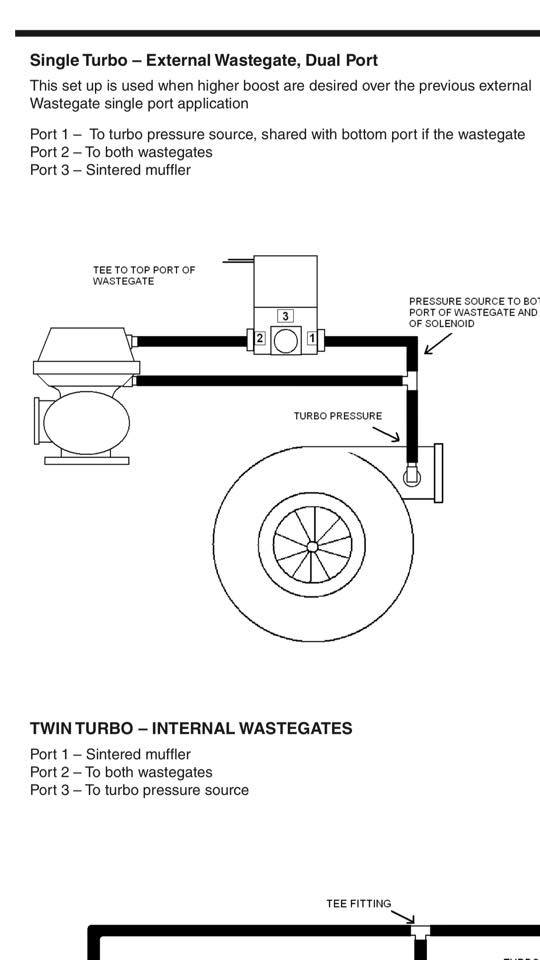
Turbo Waste Gate Solenoid Boost Pressure Vacuum Lines Connection Routing. When you are connecting the vacuum lines to/from your turbo, there's a few different ways to do it, depending on what else you have connected to the turbocharger. Waste gate, solenoids, etc., will determine how you go about accomplishing this task.









0 Response to "39 turbo vacuum line diagram"
Post a Comment