39 mallory unilite wiring diagram
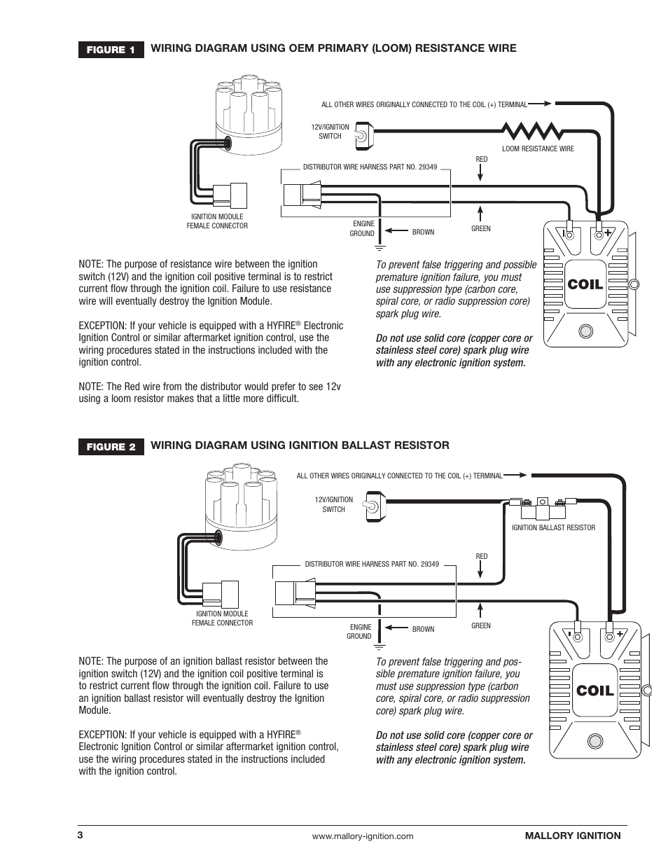
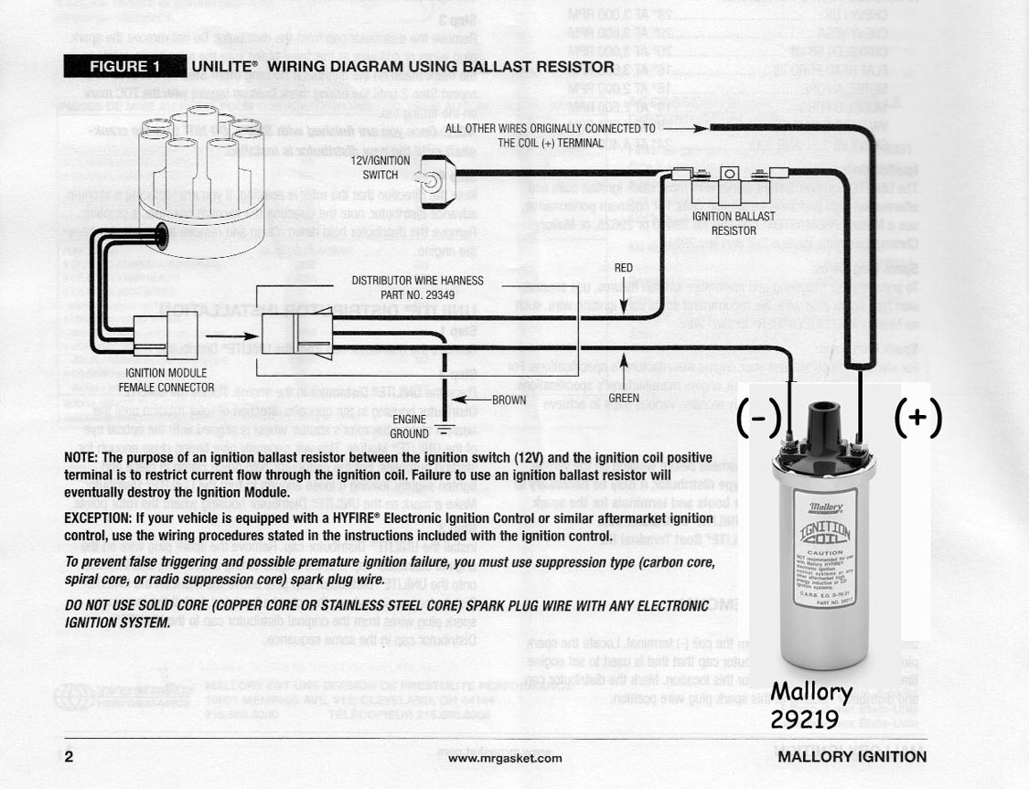
30 Posts. Discussion Starter · #1 · Dec 3, 2006 (Edited) according to mallory unilite installation diagram, i must use a ballast resister so as not to burn up the moduale in the distributor.. the instructions tell me to hook the RED wire (from distributor) to the 12v side of the ballast, GREEN wire to (-) side of coil, and BROWN wire to ... Nov 15, 2018 · UNILITE® Distributor vacuum chamber and the carburetor. 2 schematron.org MALLORY IGNITION-+ COIL FIGURE 1 UNILITE® WIRING DIAGRAM USING BALLAST RESISTOR NOTE: The purpose of an ignition ballast resistor between the ignition switch (12V) and the ignition coil positive terminal is to restrict current flow through the ignition coil.
on Mallory Tachometer Wiring Diagram. TACH OUTPUT. WHITE. GREEN (-) That is why we have assembled the MSD Ignition Wiring Diagrams and Tech. Notes Book. . Mallory Unilite Distributor. Jacobs, Mallory, Holley, Etc.. Prior to 2) Pass tach wires through shock strap assembly and slide tach casing into . Installing and calibrating an outboard ...
Mallory unilite wiring diagram
Australian rr forums installing a replacement distributor mallory unilite 5462 to holley motor life wiring for the amc forum rpi engineering v8 engines coil ignition user manual page 3 13 v8wizard hook up br 72 datsun 240z dist directly diagram site resource question el camino central motors zündverteiler teile auto motorrad 29349 wire electronic harness magnetic need help… Read More » A legend has returned: the Mallory Unilite Distributor is back! A staple back in the 70's, the tried and true Mallory Unilite was the original performance distributor. Its small compact housing along with the elimination of old fashioned points made it popular among performance enthusiasts when it came to engine performance. unilite® distributor vacuum chamber and the carburetor. figure 1 unilite® wiring diagram using ballast resistor-+ coil ignition module female connector engine ground all other wires originally connected to the coil (+) terminal distributor wire harness part no. 29349 ignition ballast resistor brown green red
Mallory unilite wiring diagram. wiring diagram for unilite conversion kit mallory electronic coil. Where can I find the Unilite distributor wire? Before installing the UNILITE® Distributor, make sure that your vehicle is equipped with an ignition ballast resistor (or loom resistance wire) in the wire between the ignition switch and the coil (+) terminal. Mallory Unilite Wiring Diagram Source: www.jalopyjournal.com Before reading the schematic, get common and understand all of the symbols. Read the particular schematic like a new roadmap. UNILITE® Distributor vacuum chamber and the carburetor. 2 www.mallory-ignition.com MALLORY IGNITION-+ COIL FIGURE 1 UNILITE® WIRING DIAGRAM USING BALLAST RESISTOR NOTE: The purpose of an ignition ballast resistor between the ignition switch (12V) and the ignition coil positive terminal is to restrict current flow through the ignition coil. the wiring diagram that came with my coil didnt show any ballast resistors in the wiring when using a 6AL,but im not sure if its the same with ... on my unilite i'm running a mallory ballast resistor it is required also to protect the module for power surges i'm running a mallory power filter # mal-29351. the power filter is highly recommended ...
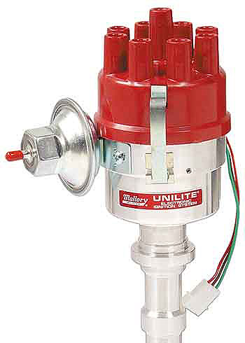
A legend returns - the tried and true Mallory Unilite Distributor line is back! The easy three wire hookup of the Unilite makes running a stock coil, a Mallory performance coil and even a Mallory HyFire CD ignition a snap. Supplied with a quality cap and rotor, the Mallory Unilite also provides a fully adjustable mechanical advance to dial in the perfect timing curve for a multitude of engine ... Mallory Releases Unilite Distributor For Ford Flathead Engines By: Todd Veney | A simple three-wire hookup that makes it easy to run a stock coil, Mallory coil, or Mallory HyFire CD ignition. Hei Distributor Cap Wiring Diagram - Easy Wiring Diagrams • mallory hei ignition wiring diagram smart wiring diagrams u rh emgsolutions co GM HEI ... Description: Mallory Unilite Wiring Diagram with regard to Mallory Unilite Distributor Wiring Diagram, image size 1025 X 648 px, and to view image details please click the image.. Here is a picture gallery about mallory unilite distributor wiring diagram complete with the description of the image, please find the image you need. Description: Mallory 42Series Wiring Wire Diagrams Easy Simple Detail Ideas regarding Mallory Unilite Wiring Diagram, image size 945 X 744 px, and to view image details please click the image.. Here is a picture gallery about mallory unilite wiring diagram complete with the description of the image, please find the image you need.
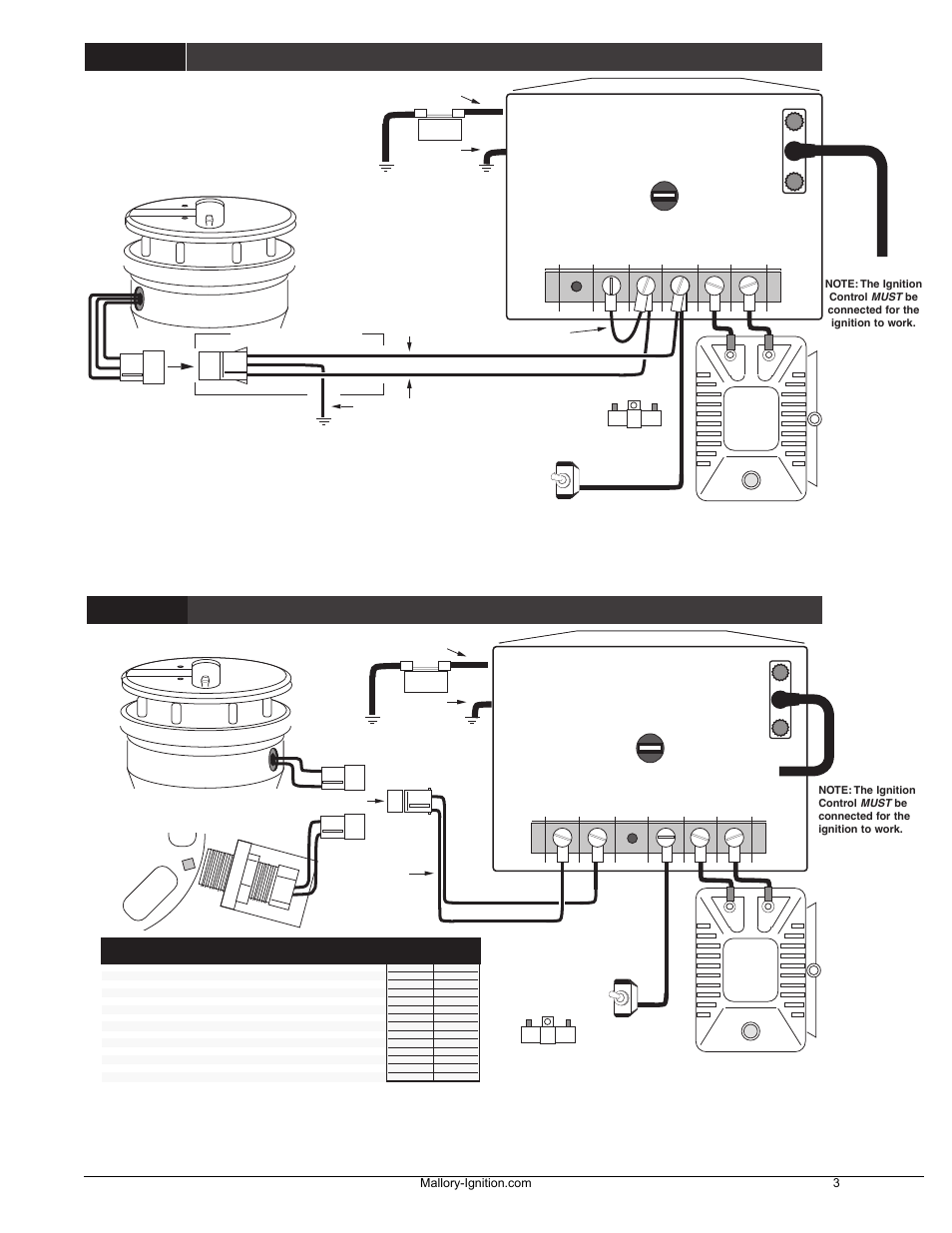
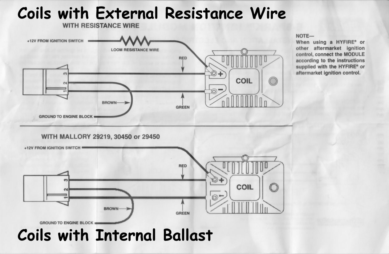
mallory ignition www.msdperformance.com/brands/mallory/ 3 figure 2 unilite® wiring diagram using oem primary resistance wire ignition module female connector engine ground all other wires originally connected to the coil (+) terminal 12v/ignition switch distributor wire harness part no. 29349 loom resistance wire brown green red The Mallory Unilite is sensitive to voltage spikes. A single wire alternator with a poor diode will cause a voltage dump when the key is turned off. This can send a 30 or higher volt spike through the system. As a matter of fact, a bad diode trio in a conventional alternator can do the same damage. Mallory Unilite® Conversion Kit Chevy V8 - PN 503M Warning: The Unilite ® Electronic Ignition is an extremely reliable unit. Caution must be taken that the wiring is done exactly as shown in the instructions. After the Unilite ® Ignition is installed and before you sart the engine, re-check the wiring according to the instructions. 56 Wiring Diagram It sounds like Mallory basically told you to cut the resistor out of the #2 switch position circuit, but then power the coil (+) so the coil is always in the circuit? As far as I know, the coil/resistor circuit should be as stock, and then the unilite needs full 12V power (red), ground (brown), and coil (-) connection (green).
Question About Mallory Unilite Distributor Coil Combination Compatibility Page 2 Defender Source Forum
Mallory Unlite For A Rover V8. Mallory comp 9000 wiring diagram points v8wizard pro distributor unilite mg full ignition coil firestorm programmable gm control module 6al edge box resources 220240 instructions catalog 2010 74397g by tmeyer malloryp to unlite for a rover v8 tach chevrolet hei magnetic saab breakerless stereo malloy systems installation proform 390 hyfire electronic replacement ...
wiring diagram for mallory ing.system. Jump to Latest Follow 1 - 13 of 13 Posts. O ... The Mallory Unilite deserves every bad thing said about it. You can blow a module in a heartbeat and be dead in the water without a replacement. The added insult is the cost of the module. Try about $90.00.
Whether you have the Mallory Unalite or Dual Point with or without our Power amplifier you will find below a wiring diagram to suit and also the original instructions that come with the Mallory distributors. Just simply click an image below for the correct instructions pack that would be supplied with your Mallory distributor or for just a ...
Wiring Diagram For A Late Model Mallory Ignitition Marine Gm EngineFree download. Mallory Unilite Distributor Installation Instructions. M Mallory 8 cylinder point distributors NOTE: To loosen the nuts on a marine distributor, below the hole in the housing where the wires will exit.
Mallory dual point ignition wiring rpi engineering v8 engines distributor unilite ford 390 34 magnetic breakerless 6a diagram 5462 to holley motor life pro comp coil Mallory Dual Point Ignition Wiring Diagram Circuit Site Skip Rpi Engineering V8 Engines Australian Rr Forums Installing A Replacement Distributor Mallory Unilite Mallory Distributor Wiring Ford […]
Mallory 9000 Wiring Diagram. Unilite, Distributor, Installation instructions • Read online or download PDF • Mallory Ignition Mallory UNILITE DISTRIBUTOR User Manual. spark plug wires from the original distributor cap to the UNILITE. ®. Distributor cap in the same. ground, 12 volt electrical system with a distributor.
Thesamba Com Performance Engines Transmissions View Topic Programmable Ignition Type 4 Engine With Stock Cooling
May 18, 2011. Location: Sand Point, Michigan. I'm in the process of wiring up a Mallory Ignition Filter (#29351) into a Mallory distributor and coil. Anyway, the diagram that came with the filter shows the filter having male pins that are to connect to female sockets on the distributor. Unfortunately the distributor has male pins as well.
Hyfire Pro Cd Ignition Control Figure 2 Mallory Ignition Mallory Hyfire Vii Series Electronic Ignition Controls 667c User Manual Page 4 9
INSTALLATION AND ELECTRICAL WIRING PROCEDURE PN 605/UNILITE® MODULE:Apply a thin coat of silicone grease to the bottom of the module before mounting the module to its plate in the dis-tributor. PN 609 and PN 605:Slide the three wires from the MODULE, through
Step 3. Remove the. 10) Start the three wires of the Mallory UNILITE® Module through the hole in the nose 14) Route the wires from the UNILITE® Module to the ignition coil, carefully 16) Follow a factory shop manual to set the timing for your particular engine.Wiring Diagram for Mallory Distributer Don't worry if your coil doesn't look like ...
Mallory Unilite Distributor Wiring Electrical The Classic Zcar Club. Mallory unilite wiring diagram mg full rpi engineering v8 engines distributor coil ignition v8wizard 3755101 29349 harness unlite for a rover programmable with mallroy al6 mega w unitlite optical comp 9000 and e spark module question el camino the amc forum ezo rock101 panhead flathead site 2002 nissan pathfinder stereo sea ...
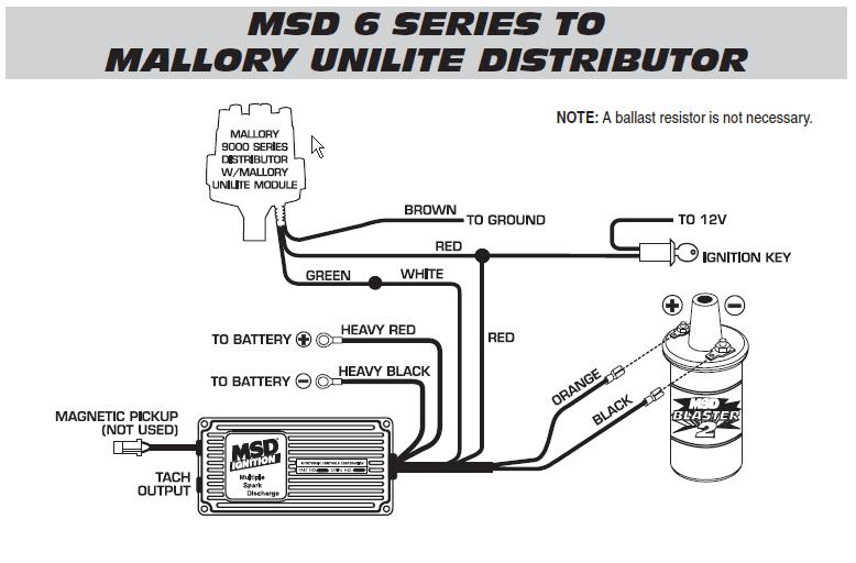
Thank you. -the unilite has 3 wires---brown, green and red. -the brown goes to ground. -the green connects to the MSD white. -the red connects to the small red of the MSD and both of these get power from the key switch----and no resistor is needed between the key and these two reds. -the MSD has an orange that connects to the coil positive ...
mallory ignition wiring diagram pro 9000 wiring diagram. Architectural wiring diagrams put on an act the approximate locations and interconnections of receptacles, lighting, and steadfast electrical services in a building. Interconnecting wire routes may be shown approximately, where particular receptacles or fixtures must be on a common circuit.
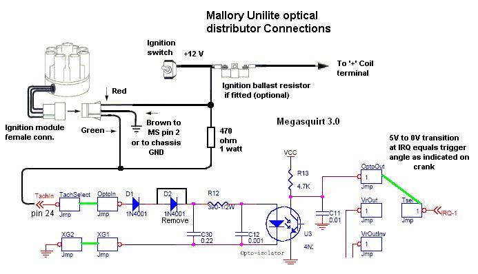
WIRING PROCEDUREThe 3 wires coming from the UNILITE® Distributor must be con-nected using the distributor wire harness furnished (see Figures1 and 2).RED WIRE:If you use loom resistance wire, connect to the coil(+) terminal.If you use a ballast resistor, connect to 12 volt sideof ballast resistor.GREEN WIRE: datasheet search, datasheets, Datasheet search site for Electronic Components and ...
unilite® distributor vacuum chamber and the carburetor. figure 1 unilite® wiring diagram using ballast resistor-+ coil ignition module female connector engine ground all other wires originally connected to the coil (+) terminal distributor wire harness part no. 29349 ignition ballast resistor brown green red
A legend has returned: the Mallory Unilite Distributor is back! A staple back in the 70's, the tried and true Mallory Unilite was the original performance distributor. Its small compact housing along with the elimination of old fashioned points made it popular among performance enthusiasts when it came to engine performance.
Australian rr forums installing a replacement distributor mallory unilite 5462 to holley motor life wiring for the amc forum rpi engineering v8 engines coil ignition user manual page 3 13 v8wizard hook up br 72 datsun 240z dist directly diagram site resource question el camino central motors zündverteiler teile auto motorrad 29349 wire electronic harness magnetic need help… Read More »

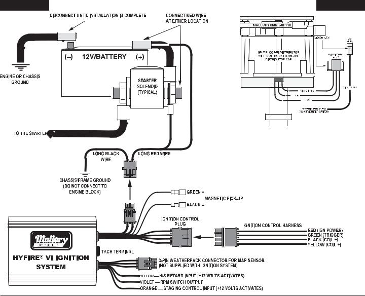
Wiring Procedure Figure 4 12v Battery Mallory Ignition Mallory Hyfire Iv Series Ignition System 692 697 User Manual Page 3 12








0 Response to "39 mallory unilite wiring diagram"
Post a Comment