39 draw the shear diagram for the beam
Answer (1 of 3): You should download 'Beamax' to draw both diagrams for you and if you need to use it online, you can just snip the pictures. 14 hours ago · Draw the shear diagram for the beam. Click on "add vertical line off" to add discontinuity lines. Then click on "add segment" button to add functions between the lines. Note - Make sure you place only one vertical line at places that require a vertical line. If you inadvertently place two vertical lines at the same place, it will appear ...
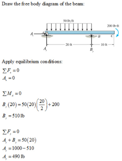
Nov 13, 2021 · Draw the shear diagram for the beam. assume that m0=200lb⋅ft, and l=20ft. Transcribed image text: Problem 6.13 Part A Draw the shear diagram for the beam. Assume that Mo 200 lb.ft, and L 20 ft. Begin by placing the lines of discontinuity.

Draw the shear diagram for the beam
Therefore the bending moment diagram is: Example 2 Draw the shear force and bending moment diagrams for the beam show below: a) determine the reactions at the supports Taking moments about A (clockwise moments = anti-clockwise moments) (10 x 6) x 3 = 6RC where 10 x 6 =60kN = total load and 3m =distance from A to where the load is acting. 6RC=180 Draw shear force and bending moment diagram of simply supported beam carrying uniform distributed load and point loads. As shown in figure. Solution. First find reactions R1 and R2 of simply supported beam. Reactions will be equal. Since, beam is symmetrical. R1 = R2 = W/2 = (600 +600 + 200 x4)/2 = 1000kg. Hence, R1 = R2 = 1000 kg. Shear Force ... First draw the free-body-diagram of the beam with sufficient room under it for the shear and moment diagrams (if needed, solve for support reactions first). 2. Draw the shear diagram under the free-body-diagram. The distributed load is the slope of the shear diagram and each point load represents a jump in the shear diagram. Label all the loads ...
Draw the shear diagram for the beam. 2) Calculate the shear force and bending moment diagram of the beam as shown in the figure. Also draw shear force diagram (SFD) and bending moment diagram (BMD). Solution; Free body diagram of the given figure is given below; Taking moment about point B , we get. ƩM B = 0. R Ay x 6 - 10 x 4 - 10 x 2 = 0. 4.3 Shear- Moment Equations and Shear-Moment Diagrams The determination of the internal force system acting at a given section of a beam : draw a free-body diagram that expose these forces and then compute the forces using equilibrium equations. The goal of the beam analysis -determine the shear force V and Part B Draw the moment diagram of the beam. Shear and Moment Diagram of a Cantilever Beam: Method of area is an interesting method to use if you have a load that is uniformly distributed and a ... Axial Force, Shear Force and Bending Moment Diagrams for Plane Frames Previous definitions developed for shear forces and bending moments are valid for both beam and frame structures. However, application of these definitions, developed for a horizontal beam, to a frame structure will require some adjustments.
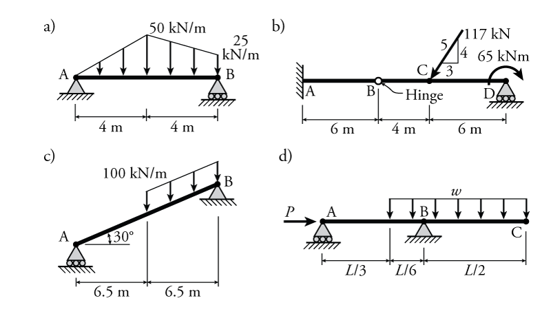
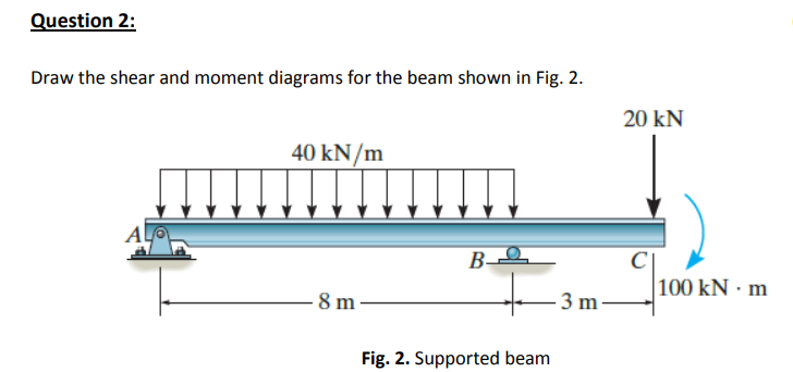
1 - Draw the shear and bending moment diagrams for the beam and loading shown. There is an internal pin at point B. Align a drawing of the structure and the diagrams vertically. Indicate values for points that define the shape of each diagram. 14 kN 8 kN/m 4 kN/m B. 3m 2 1 Please compute the shear AND moment diagrams with steps. Thanks. Draw the shear and moment diagrams for the beam. (Figure 1) Draw the shear diagram for the beam. Click on "add discontinuity" to add discontinuity lines. Then click on "add segment" button to add functions between the lines. Draw the shear and moment diagrams for the beam. Now, flip the beam horizontally 180º (or change the observation point, looking at the beam from the opposite side) and draw the diagrams, starting from the same point A. The diagrams will appear as follows: Note that, while the shear force diagrams appeared to be mirrored images (flipped horizontally), the bending moment diagram is not affected. The shear diagram will plot out the internal shearing forces within a beam, or other body that is supporting multiple forces perpendicular to the length of the beam or body itself. The shear and moment diagrams are both used primarily in the analysis of horizontal beams in structures, such as floor joists, ceiling joists, and other horizontal ...
Draw shear force and bending moment diagrams [SFD and BMD] for beam. Also determine maximum hogging bending moment. 30N/m 4m [Ans: Max. Hogging bending moment = 735 kNm] Exercise Problems 4m3m VM-79 80. 5kN 8. A cantilever beam of span 6m is subjected to three point loads at 1/3rd points as shown in the Fig. given below. Draw SFD and BMD for ... Shear Force and Bending Moment Diagram for a simply supported beam are as follows. Case 01. Simply supported beam with point load. Simply supported beam with point load. To find out Shear Force, first we will calculate R a and R c. Beam is simply supported ∑M a = ∑M c = 0. Let us consider ∑M a = 0. 6*4 - R c *8 = 0 (Clockwise bending ... 1. Draw the beam to scale (horizontally). The resulting shear and moment diagrams will also be drawn to this horizontal scale. These scaled drawings can be used to check our calculations for reasonableness. 17 ft 8 ft Span 1 Span 2 wD = 0.5klf wL = 1.0klf wD = 0.5klf wL = 1.0klf wD = 0.5klf wL = 1.0klf 4.0 Building Shear and Moment Diagrams. In the last section we worked out how to evaluate the internal shear force and bending moment at a discrete location using imaginary cuts. But to draw a shear force and bending moment diagram, we need to know how these values change across the structure.
Draw The Shear Force Diagram And Bending Moment Diagram For The Beam Loaded As Shown In Fig
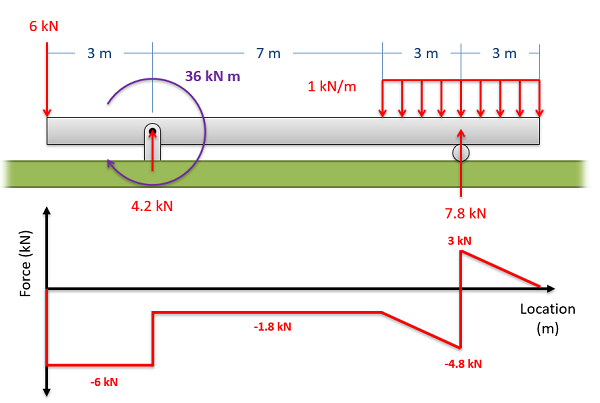
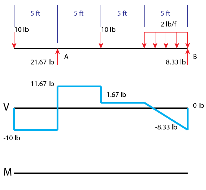
Shear diagrams always begin and end at zero, with all of the forces on the member shown in between.Starting from the left, the first force you come across is the 10 lb downward force at the left end. This is the first point of data, draw a line from zero to negative 10.. Continuing on the next force is 21.67 lb upward at the A support.
2
These instructions will help you to calculate and draw shear and bending moment diagram, as well as draw the resulting deflection. Knowing how to calculate and draw these diagrams are important for any engineer that deals with any type of structure because it is critical to know where large amounts of loads and bending are taking place on a beam so that you can make sure your structure can ...
4 5 Practice Problems Learn About Structures
Answer to Draw the shear and Moment diagrams for the overhang beam. How the bending moment diagram of an overhanging beam will be if only we can draw the shear force diagram since it dictates the shape of bending moment . 6-5. Draw the shear and moment diagrams for the beam. 2 m. 3 m. 10 kN. 8 kN. 15 kNm. 6-6.

Draw The Shear And Moment Diagrams For The Compound Beam Holooly Com
1. (a) Draw the shear diagram of the beam shown below. (b) What is the value of the maximum moment? (c) Determine the location of the maximum moment from A.

Draw The Shear And Moment Diagrams For The Beam Docsity
A Review Draw the shear diagram for the beam. Follow the sign convention. (Figure 1) Click on "add vertical line off to add discontinuity lines. Then click on "add segment" button to add functions between the lines. Note 1 - Draw a vertical line to denote local maximum or minimum. Note 2 - The curve you choose from the drop-down is only a ...

For The Figure Below Draw The Shear And Moment Diagrams For The Beam Study Com
the beam given below and draw the shear and moment diagrams. A B C 14 kN 2 m 3 m 2 m D 28kN. Example : Determine the shear and moment equations of the beam given below and draw the shear and moment diagrams. A B 16 kN.m 3 m 1 m C. Example : Determine the shear and moment equations of the beam given below and draw the shear and moment diagrams.
Hibbeler R C Structural Analysis
Draw the shear diagram for the beam. Click on "add discontinuity" to add discontinuity lines. Then click on "add segment" button to add functions between the lines. Part B. Draw the bending-moment diagram for the beam. Click on "add discontinuity" to add discontinuity lines. Then click on "add segment" button to add functions between the lines.

4 5 Practice Problems Learn About Structures
Steps to draw Shear force and Bending moment diagrams. In SFD and BMD diagrams Shear force or Bending moment represents the ordinates, and the Length of the beam represents the abscissa. Consider the left or the right portion of the section. Add the forces (including reactions) normal to the beam on the one of the portion.
2
drawing the S/B diagrams. [1,2]The method of sections can be used to determine fully the shear force and bending moment at any cross-section of beams and to draw the S/B diagrams. When there are several external forces on a beam, the beam must be divided into several segments. The method of sections will be used repeatedly in each segment.

Drawing Bending Moment Diagrams Effectively Mechanicalbase
.7—41. Draw the shear and moment diagrams for the simply supported beam. Since the loading discontinues at the 9- kN concentrated force, the shear and moment equations must be written for the regions O x < 4 m and 4 m < 6 m Of the beam. The free - body diagrams of the beam's segment sectioned through
2
This is a tutorial to make shear force diagram and bending moment diagram easily for a simply supported beam loaded with concentrated loads. the method indic...
Mechanics Map Shear And Moment Diagrams
Write shear and moment equations for the beams in the following problems. In each problem, let x be the distance measured from left end of the beam. Also, draw shear and moment diagrams, specifying values at all change of loading positions and at points of zero shear. Neglect the mass of the beam in each problem.

Drawing Bending Moment Diagrams Effectively Mechanicalbase
Nov 15, 2021 · Home › draw the shear and moment diagram for the beam › draw the shear diagram for the beam › draw the shear diagram for the beam. 7.78 › draw the shear diagram for the beam. assume that m0=200 lb⋅ft and l=20ft › draw the shear diagram for the beam. assume that w0=10kip/ft and l=18ft › draw the shear diagram for the beam. follow ...
Solved Draw The Shear Diagram For The Beam Draw The Moment Chegg Com
a Shear and Moment Diagram : Constructing shear and moment diagrams is similar to finding the shear and moment at a particular point on a beam structure. However, instead of using an exact location, the location is a variable distance 'x'. This allows the shear and moment to be a function of the distance, x.

Draw The Shear Diagram For Beam Beams Bending Moment Image House
Consider the free body diagram of the beams ABE and CBD of the beam separately and apply the force equilibrium equations to calculate the unknown support reactions at A, B, C and D.Consider a section between each segment of the beam and apply the equilibrium equations to calculate the shear force and bending moment at each location of the beam.
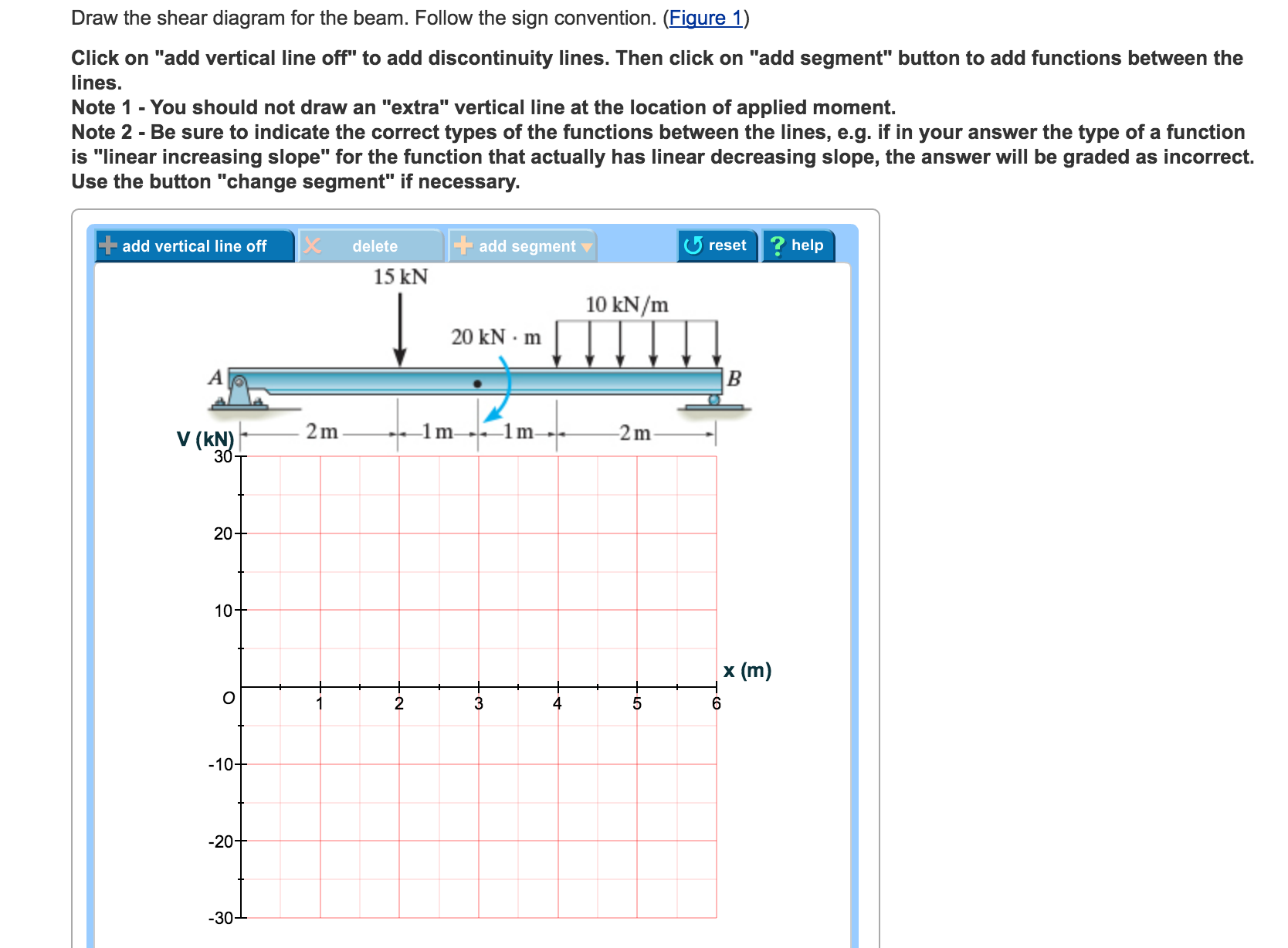
Solved Draw The Shear Diagram For The Beam Follow The Sign Chegg Com
First draw the free-body-diagram of the beam with sufficient room under it for the shear and moment diagrams (if needed, solve for support reactions first). 2. Draw the shear diagram under the free-body-diagram. The distributed load is the slope of the shear diagram and each point load represents a jump in the shear diagram. Label all the loads ...

How To Calculate And Draw Shear And Bending Moment Diagrams 13 Steps Instructables
Draw shear force and bending moment diagram of simply supported beam carrying uniform distributed load and point loads. As shown in figure. Solution. First find reactions R1 and R2 of simply supported beam. Reactions will be equal. Since, beam is symmetrical. R1 = R2 = W/2 = (600 +600 + 200 x4)/2 = 1000kg. Hence, R1 = R2 = 1000 kg. Shear Force ...
Solved Problem 7 75 Part A Draw The Shear Chegg Com
Therefore the bending moment diagram is: Example 2 Draw the shear force and bending moment diagrams for the beam show below: a) determine the reactions at the supports Taking moments about A (clockwise moments = anti-clockwise moments) (10 x 6) x 3 = 6RC where 10 x 6 =60kN = total load and 3m =distance from A to where the load is acting. 6RC=180
The Ultimate Guide To Shear And Moment Diagrams Degreetutors Com
Answered Draw The Shear Diagram For The Beam And Bartleby
Answered Draw The Shear And Moment Diagrams For Bartleby

Draw The Shear And Moment Diagram For The Beam And Loading Shown Study Com
Chapter 4 Internal Forces In Beams And Frames In Structural Analysis On Manifold Tupress
2
Solved Draw The Shear And Moment Diagrams For The Beam The Supports At A And B Are A Thrust And Journal Bearing Respectively
2
Draw The Shear Diagram For The Beam Home Work Help Learn Cbse Forum

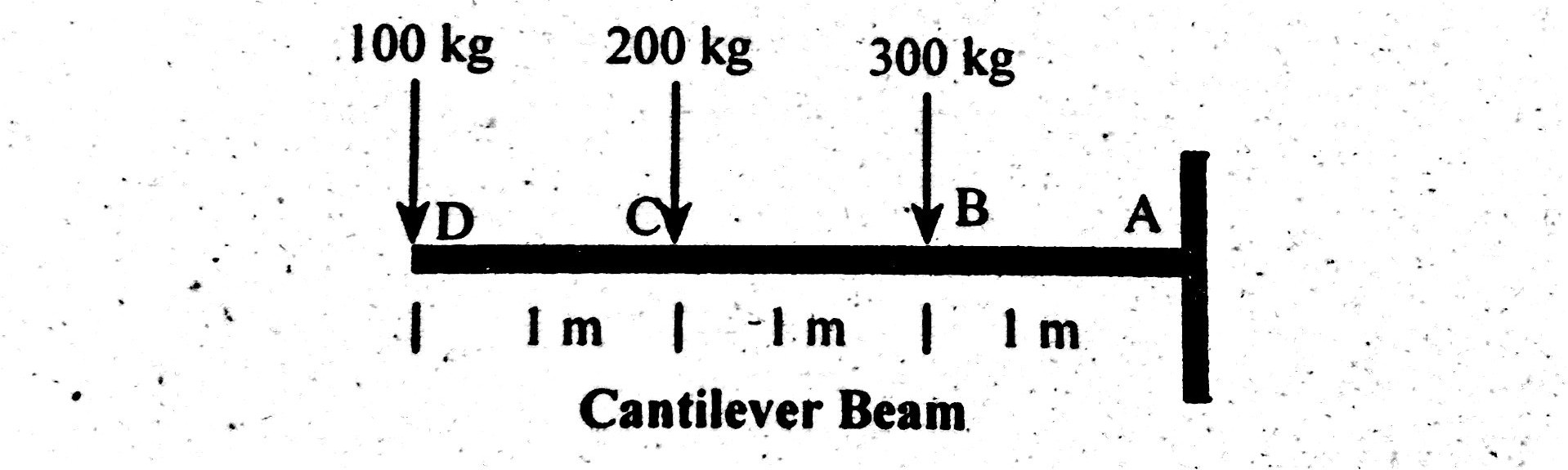
Draw Shear Force And Bending Moment Diagram For Cantilever Beam Bending Moment Shear Force Mathematical Expression

Shear And Moment Diagram Wikipedia

Part A Draw The Shear Diagram For The Beam Follow The Itprospt
How To Draw Moment Diagrams Reviewcivilpe
1
Draw The Shear

Shear Force And Bending Moment Diagrams Graphical Method Slide Share

329 6 1 Draw The Shear And Moment Diagrams For Aerostudents
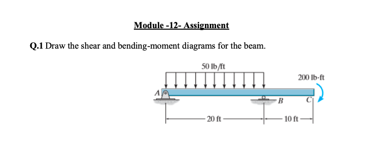
Solved Module 12 Assignment Q1 Draw Shear Bending Moment Diagrams Beam 50 Lb Ft 200 1b Ft 10 Ft 2 Q37176267
Bending Shear And Moment Diagram Graphical Method To Construct Shear Ppt Download
Shear Force Bending Moment Diagram Of Cantilever Beam Examples Engineering Intro

Shear Force And Bending Moment Diagrams Wikiversity
0 Response to "39 draw the shear diagram for the beam"
Post a Comment