42 marine fuel sending unit wiring diagram
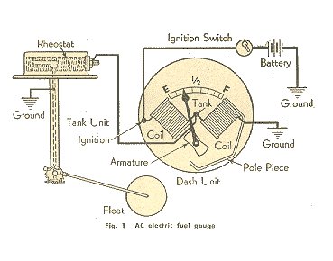
marine fuel gauge wiring diagram - Wiring Diagram and ... 1963 1967 Corvette Fuel Gauge Wiring Schematic Will Inc. Fuel Gauge To Cell Sending Unit Honda Tech Forum Discussion. 2 12v Fuel Level Gauge Resistance 240 33 Ohm 24v Rv Universal Oil Meter E 1 F Indicating Range Lighting Background Anti Fogging Rust Waterproof Stainless Stress Frame For Boat Marine Online In Turkey. Moeller Fuel Gauge Wiring Diagram Moeller Gauge-Wiring Diagram 4″″ Universal Electric Fuel Sender Instructions Electric Fuel . Gauge pointer should be at the position shown in the lower portion of the diagram. To test senders, the resistance values are shown at minimum and full gauge scales. Fuel Systems (Marine) Voltage - "I" to "G" terminal - 10 to 16 volts. 52 results
Wiring Gauge Fuel [G1OALR] There is also a second wiring diagram in my '49 with '50 - '51 supplement page 12-2 that shows the wire gauges. Wiring Diagrams For Vdo Gauges Valid Marine Fuel Gauge Wiring from boat fuel gauge wiring So, if you desire to receive the incredible images regarding (Boat Fuel Gauge Wiring Diagram. I burned up two fuel gauges before I found this out.
Marine fuel sending unit wiring diagram
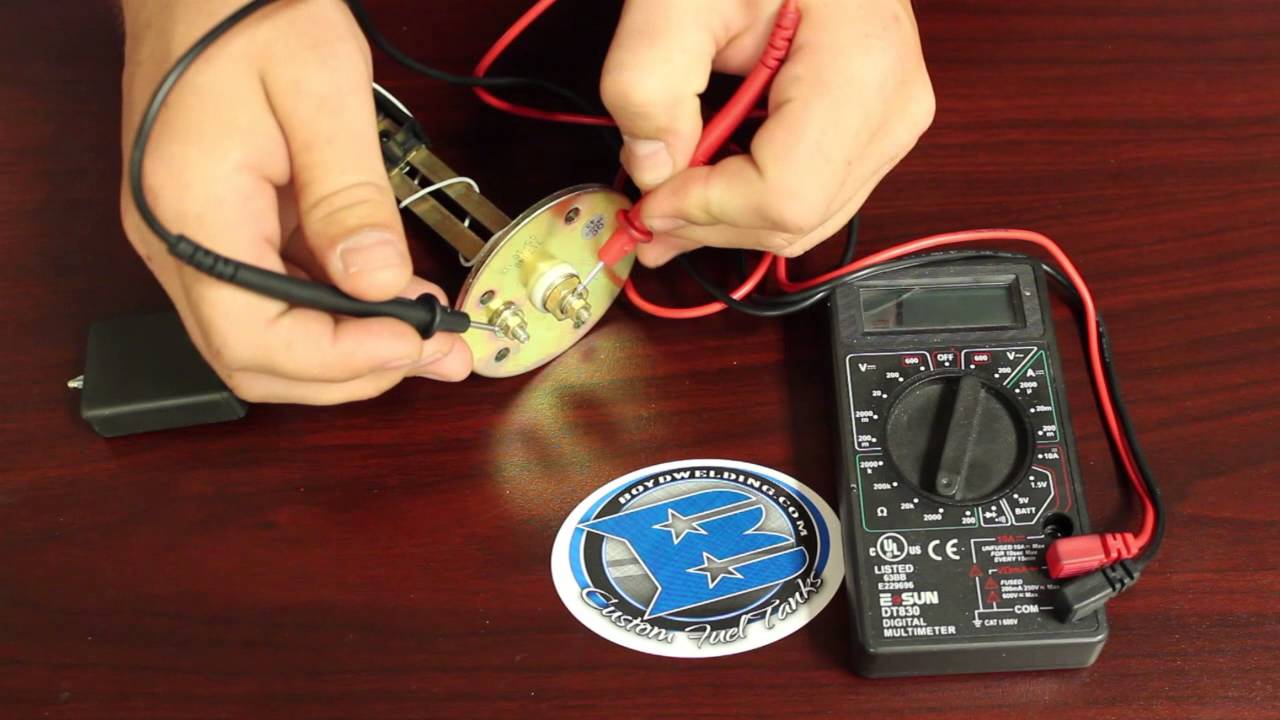
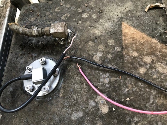
PDF FUEL LEVEL SENDER - Livorsi Marine, Inc. 3) SEND and NEG wires reversed on Sending Unit. 4) Meter not grounded properly. 5) SEND wire is touching NEG terminal or wiring 6) Center rod on fuel units touching the outside tube. 7) Unit not calibrated. Water tank only: End of tube not sealed properly. WATER TANK SENDERS 1. The water tank units are not interchangeable with the fuel units. 2. How to wire up a fuel sending unit? - JustAnswer The fuel tank should be grounded and the sender wire pink should be connected to the sender terminal on the sending unit this is the correct wiring. The sending unit will ground through the mount screws. The fuel gauge reads the resistance to ground check the wires on the back of the gauge pink to S terminal and black to G terminal. Boat Fuel Gauge Not Working | Boating Mag A jumper wire fitted with alligator clips is a cheap and effective troubleshooting tool. So is a screwdriver. Boating Magazine. Boat fuel gauges can be troublesome. Here is a quick method of determining whether the fault lies in your boat's fuel gauge or in the fuel gauge sending unit on the tank.
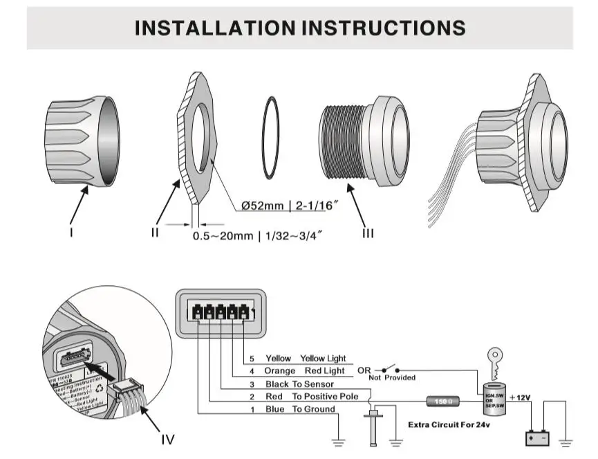
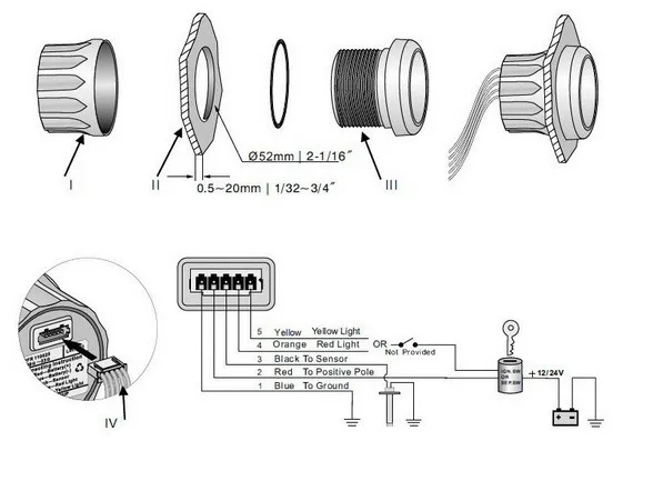
Marine fuel sending unit wiring diagram. PDF KUS Electric Sending Unit Installation Guide WARNING ... Connect (black) wire. from the KUS sending unit to gauge hook-up. If your gauge has color coded hook-ups, maintain this coding as you connect the sender and ground wires. WARNING!! GASOLINE IS EXTREMELY FLAMMABLE. KEEP TANK AREA FREE FROM SPARKS AND FLAMES. EMPTY THE TANKS OF FUEL & FUMES BEFORE CONTINUING WITH INSTALLATION. Moeller Fuel Gauge Wiring Diagram - schematron.org The fuel tank should be grounded and the sender wire pink should be connected to the sender terminal on the sending unit this is the correct wiring. The sending unit will ground through the mount screws. The fuel gauge reads the resistance to ground check the wires on the back of the gauge pink to S terminal and black to G terminal. Spectacular Boat Fuel Sending Unit Wiring Two Circuits On ... The fuel tank should be grounded and the sender wire pink should be connected to the sender terminal on the sending unit this is the correct wiring. Then disconnect both the sending wire and ground wire on the old sending unit. There may also be a ground wire coming off a second post at the edge of the flange. Troubleshoot Your Boat's Fuel Gauge | Boating Mag The sending unit in the tank moves with the fuel level. Locate the sending unit at the top of the fuel tank. It's a small round plate with two wire connections. The sender changes resistance (ohms) variably as the float moves from full (up) to empty (down). Changes in resistance move the gauge needle.
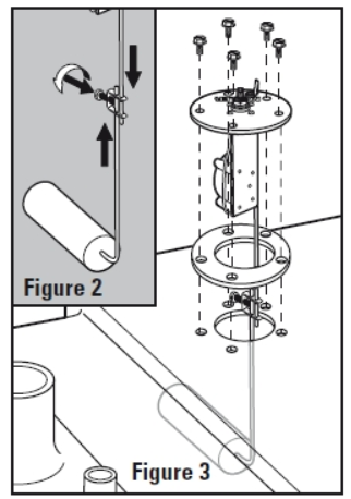
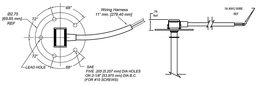
How to Wire a Fuel Sending Unit - It Still Runs The fuel sending unit is responsible for what the fuel gauge on your vehicle reads. There are two types of sending units; the older float style, which uses a magnet embedded in a float that resides in a tube, sending readings of how high in the tank it is floating, and there is the newer style that measures electrical resistance of the volume of fuel in the tank. How to install a Moeller fuel gauge - Jamestown Distributors Install your electric fuel sender, gently inserting float arm into tank followed by sending unit. Align screw holes between gasket, mounting plate and tank. Secure sending unit to tank, tightening mounting screws into place just until white sealant shows beneath the screw head. DO NOT OVER-TIGHTEN. Fuel Tank Sending Units - Marine Parts Source Maintain a high-performing fuel system with a quality marine fuel tank sending unit. Shop top brands like Moeller Marine, VDO & Wema USA. Ships same day! How to Install a Level Sending Unit | KUS USA Step 9 Once the level sending unit is installed, it needs to be connected to a gauge.T he below wiring should be followed: . 1) Connect ground (pink) wire from the KUS sending unit to a common grounding hook-up. 2) Connect (black) wire from the KUS sending unit to gauge hook-up. If your gauge has color coded hook-ups, maintain this coding as you connect the sender and ground wires.
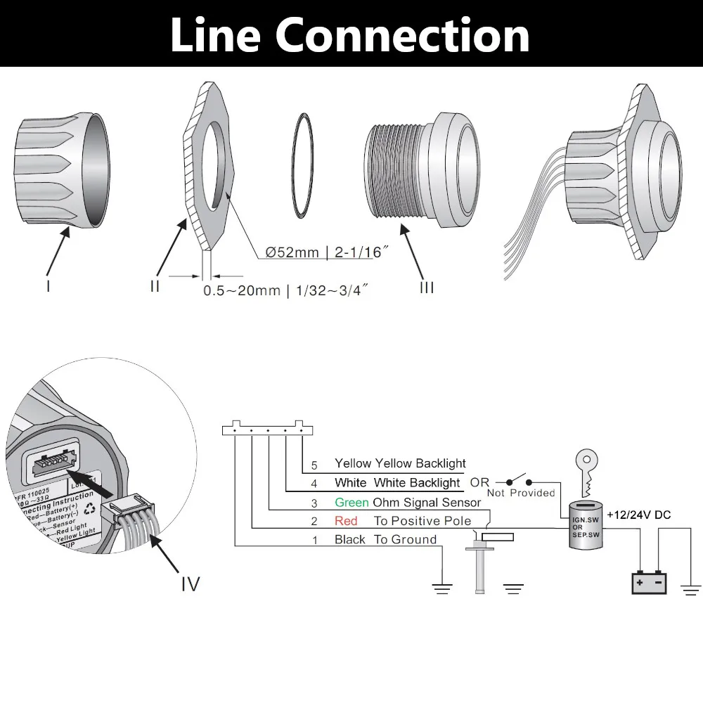
Wiring Diagram For A Boat Fuel Gauge - Wiring Diagram Line Wiring Schematic For Fuel Gauge On Nonsuch 30 Cruisers Sailing Forums Installation Troubleshooting Boat Gauges Instrumenteters Boatus 2 12v Fuel Level Gauge Resistance 240 33 Ohm 24v Rv Universal Oil Meter E 1 F Indicating Range Lighting Background Anti Fogging Rust Waterproof Stainless Stress Frame For Boat Marine Online In Turkey Kus Fuel Gauge Wiring Diagram - schematron.org run wiring from gauge to fuel cell. Connect the Black wire from the Probe to the "G" or Ground terminal on your gauge. Connect the Red wire to the "S" or Sender terminal on your gauge. Connect the yellow wire to the Gold terminal on the Low Level LED Lamp and connect the silver terminal on the lamp to Ground. Connect the "I. wiring instructions. How to Test and Replace your Fuel Gauge and Sending Unit Check the wiring diagram that comes with the kit and mark the back of the new fuel gauge with symbols for each post: "S" for the sender, "G" or "—" for the ground, and "I" for the ignition. Install the new gauge, reconnect the wiring and turn on the power. The fuel gauge should now show the correct fuel level in the tank. Gas tank sending unit wiring diagram help | Boating Forum 1. with key on, bridge or connect center wire on tank (usually pink) to the tank ground wire. If the tank has a spade connector, make sure its clean and tight. a. if Gage pegs to full, problem is in the sender in the tank (most likely) b. if gage does not move, ground the tank to the negative battery terminal and see if the gage pegs.
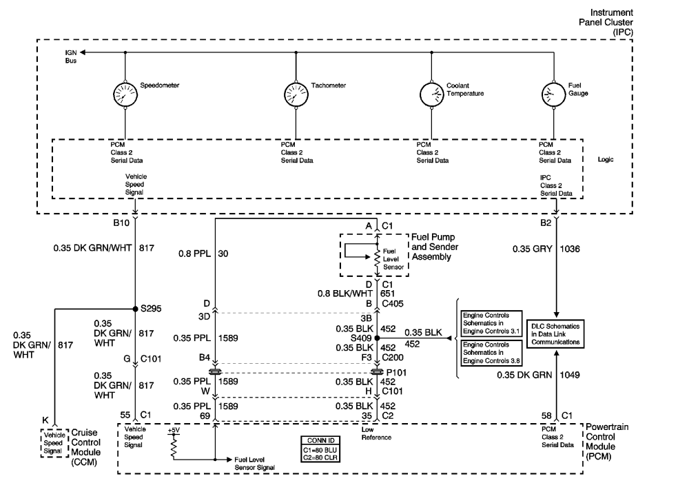
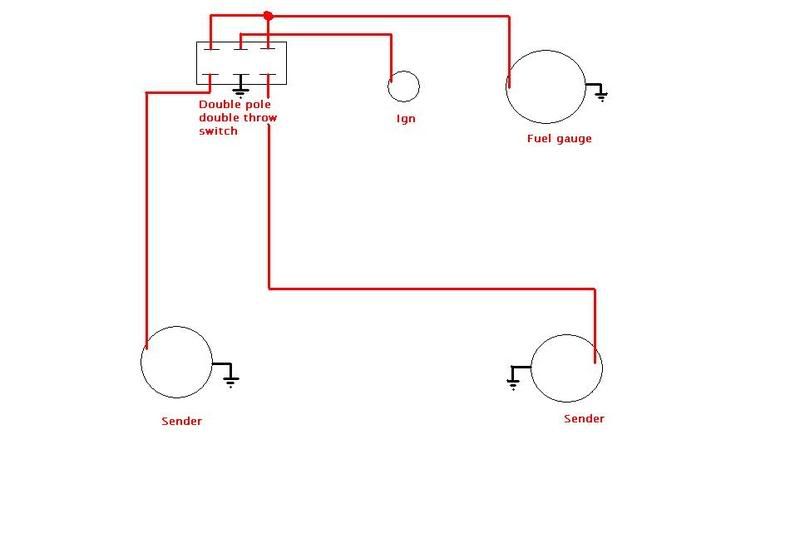
Fuel sending unit wiring diagram to PCM and Instrument ...
Wiring Diagram For Boat Fuel Sending Unit - Wiring Diagram ... How to test and replace your fuel gauge sending unit sail magazine sender wiring question the hull truth boating fishing forum troubleshoot boat s mag dual units one ...
Troubleshooting Boat Gauges, Instruments and Meters | BoatUS
Fuel Tank Sending Unit Wiring | Boating Forum - iboats ... The "S" wire from the gauge gets connected to the threaded post on the sender at the tank. The tab is the ground for the sender and it goes to the negative terminal of the battery or to the engine block. A second ground wire should run up to the filler port for the tank. The sender itself does not have +12 volts on it. Here is a diagram.
WIFI Fuel &Water Level Gauge Boat Motorcycle Car Fuel Sending ...
Gm Fuel Sending Unit Wiring Diagram - Cadician's Blog Boat Fuel Sending Unit Diagram | Wiring Diagram - Gm Fuel Sending Unit Wiring Diagram Wiring Diagram comes with a number of easy to follow Wiring Diagram Instructions. It really is meant to aid all of the common person in building a suitable system. These instructions will probably be easy to understand and implement.

Boat-Project.Com - Installing a Rudder Indicator
Peerless Marine Fuel Sending Unit Wiring Diagram L298n ... Search for marine fuel sending unit wiring diagram here and subscribe to this site marine fuel sending unit wiring diagram read more. It shows the components of the circuit as simplified shapes and the power as well as signal connections in between the devices. To make sure the readings are accurate top off the tank.
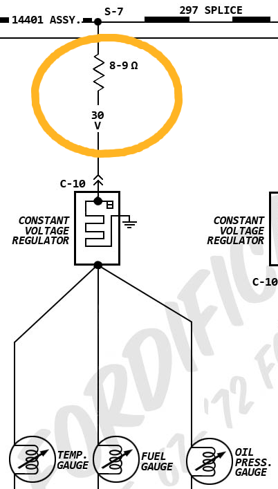
Gauges, Instruments and Switches | Valve Chatter
Fuel Gauge Wiring Diagram - Wiring diagram online Automotive Fuel Gauge Wiring Diagram Top Automotive Wiring Diagram Pics Of Wiring Diagrams from tonetastic.info I need to find the schematic for the fuel guage sending unit. Wiring a fuel gauge is much the same as wiring any other gauge on your boat: Includes hardware and adapters for basic installation on gm cars.

SAMDO Universal Fuel Gauge Digital Fuel Level Gauge Marine ...
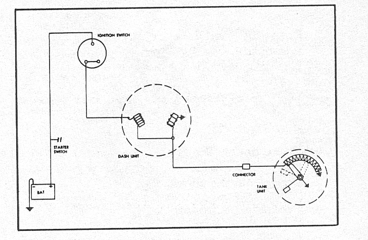
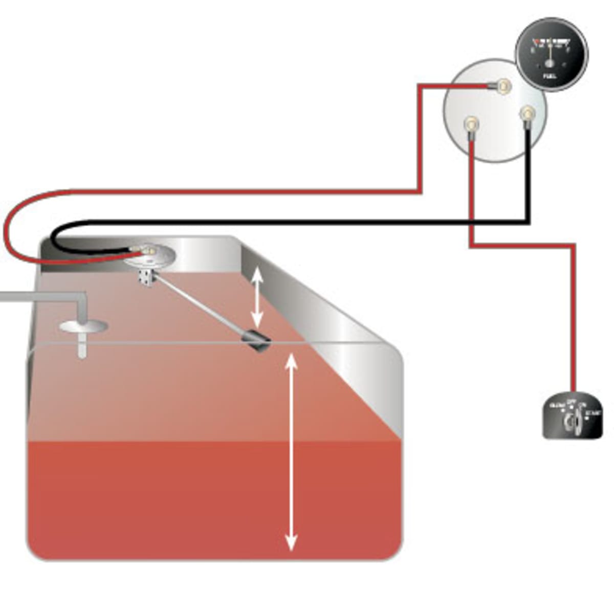
PDF Gauge and Sending Unit Wiring Diagram and ... - Moeller Marine Gauge and Sending Unit Wiring Diagram and Industry Recommendations. IGNTION SWITCH BLACK BULB SENDER GRND SENDER BATTERY GROUND FUEL . Recommended Marine Wiring Color Code Direct Current Systems - Under 50 Volts (No diagram required if wiring is in compliance with Tables I and Il) Color Yellow w/Red Stripe (YR) Yellow (Y) Dark Gray (Gy) Brown (Br)
dual fuel tank wiring diagram/ help | Performance Boats Forum
Wema Fuel Sender Wiring Diagram Parts of the Fuel Level Sender Unit to be Ad Fuel Level Sender Installation: Refer to the VDO catalog for matching fuel gauges. The unit can be adjusted to read accurately in tanks from 6" to 23" deep. Diagram B I. Measure the depth of your fuel tank. Locate this dimension in Column "A" of Table 1. Column "B" shows the length from the underside. PROPER WIRING INSTALLATION: Connect ground (pink) wire from the WEMA sending unit to a common grounding hook-up.
Fuel Gauge Adjusting - jeep parts jef
Boat Fuel Gauge Wiring Diagram - Wiring Diagram May 07, 2019 · Here is a quick method of determining whether the fault lies in your boats fuel gauge or in the fuel gauge sending unit on the tank. Connect hot wire to the i terminal and ground wire to g terminal. Wiring a fuel gauge is much the same as wiring any other gauge on your boat. The fuel gauge should now show the correct fuel level in. Get a new one. How to wire a marine fuel tank gauge by will charpentier. Test gauge as follows. Connect ground wire to 14 fasson terminal on sender.

I have a 2007 chevy tahoe, check engine light has been on for ...
Boat Fuel Gauge Not Working | Boating Mag A jumper wire fitted with alligator clips is a cheap and effective troubleshooting tool. So is a screwdriver. Boating Magazine. Boat fuel gauges can be troublesome. Here is a quick method of determining whether the fault lies in your boat's fuel gauge or in the fuel gauge sending unit on the tank.

Fuel Shutoff Solenoid Wiring 101 - Seaboard Marine
How to wire up a fuel sending unit? - JustAnswer The fuel tank should be grounded and the sender wire pink should be connected to the sender terminal on the sending unit this is the correct wiring. The sending unit will ground through the mount screws. The fuel gauge reads the resistance to ground check the wires on the back of the gauge pink to S terminal and black to G terminal.
Fuel Gauge / Fuel Sending Unit - CorvetteForum - Chevrolet ...
PDF FUEL LEVEL SENDER - Livorsi Marine, Inc. 3) SEND and NEG wires reversed on Sending Unit. 4) Meter not grounded properly. 5) SEND wire is touching NEG terminal or wiring 6) Center rod on fuel units touching the outside tube. 7) Unit not calibrated. Water tank only: End of tube not sealed properly. WATER TANK SENDERS 1. The water tank units are not interchangeable with the fuel units. 2.
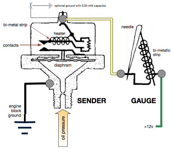
Fuel Pressure Gauge
How to install a Moeller fuel gauge – Jamestown Distributors
Electric Fuel Sender Installation Guide - Moeller Marine Online
Fuel Sending Unit Help - The Hull Truth - Boating and Fishing ...
Smiths Fuel Gage Troubleshooting
Fuel Sender 101 - TeamTalk
Troubleshooting Boat Gauges, Instruments and Meters | BoatUS

Dual Station Converter

Figure 20. Fuel tank sending unit, removal and installation.

VDO FUEL TANK GAUGE Operating instructions | Manualzz
Kus New 240-33ohm Signal Fuel Gauge Boat Oil Tank Level ...

Fuel Gauge - Working or not?
Wema fuel gauge stuck on full! - RIBnet Forums

Buy Fuel Gas Sender,Fuel Sending Unit for Boat Truck Car ...

0-90 ohm Sending Unit, SU
How to find sending unit Ohm range
Replaced Fuel Sending Unit - still not working - The Hull ...

7.5 Inch to 22 Inch Tank Depths Renewed Mechanical Fuel Tank ...
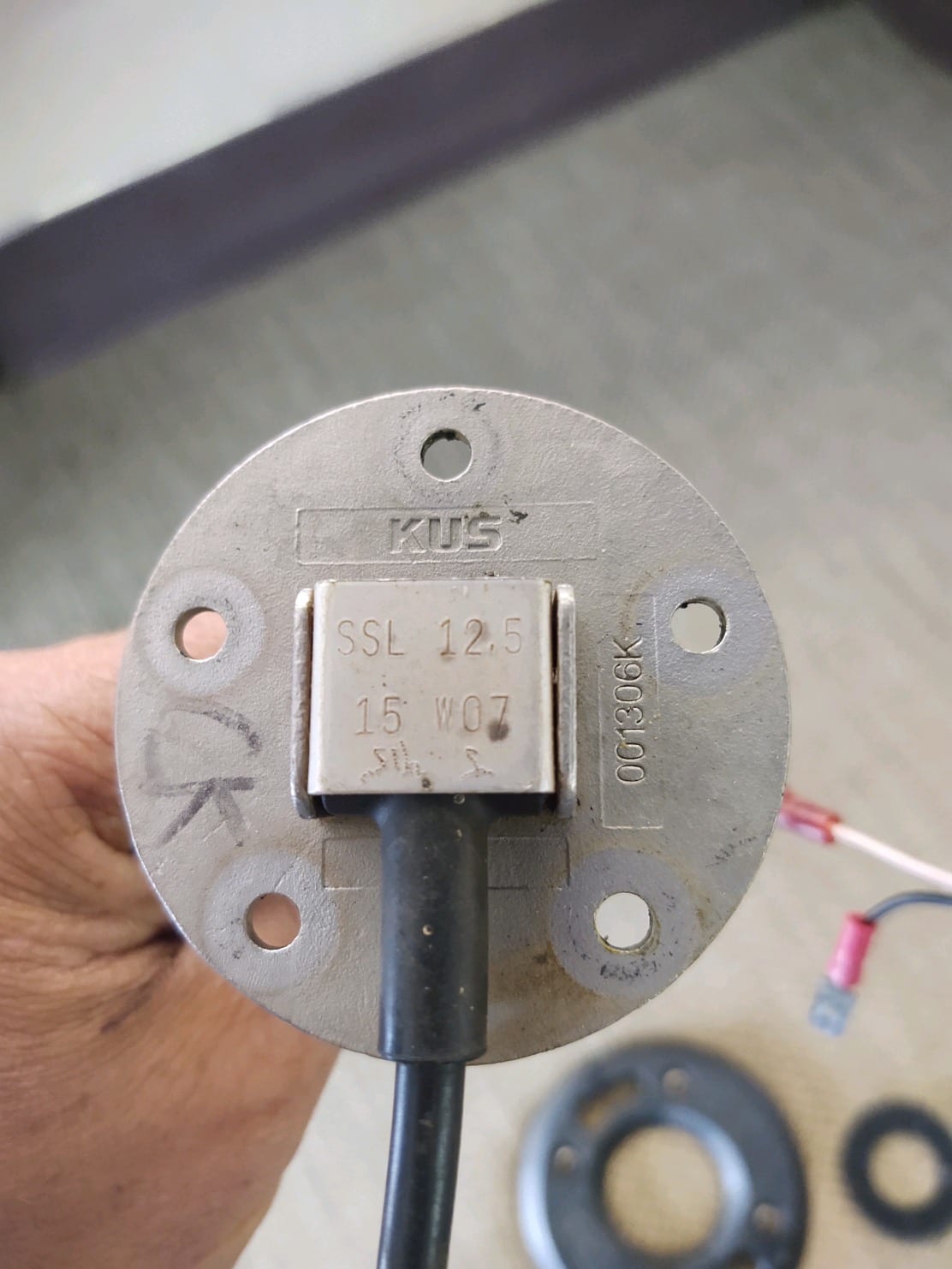
How to Install a Level Sending Unit | KUS USA
9800 Marine | Rochester Gauges
52mm Fuel Level Gauge Fuel Tank Gauge 240-33 Ohm Signal White ...

KUS - WEMA - Fuel Water Tank Level Sensor

Amazon.com: Auto Gauge Fuel Level Meter Automotive ...

Moeller Marine Electric Universal Fuel Tank Sending Unit (10 ...
How to Test and Replace your Fuel Gauge and Sending Unit ...
Could I ask for advice on attaching my Teleflex/V3 gauges ...
How To Troubleshoot Your Marine Fuel Level Sender | KUS USA

Installed new gauges in my pontoon boat. They all work except ...

Universal Fuel Sender Questions and Troubleshooting

1963-1967 Corvette Fuel Gauge Wiring Schematic | Willcox ...

How to wire up a fuel sending unit?
0 Response to "42 marine fuel sending unit wiring diagram"
Post a Comment