41 auto meter wire diagram
Tracker Boats Wiring Diagram | TackleReviewer 30/03/2010 · I replaced the switch and now the up doesn’t work at all. I believe I have deduced, that the wire that connects to the up (switch) is the problem. I am trying to find out the way to replace that wire. I can’t find a wire diagram for the boat and am not sure where that wire goes (connects to) other than the battery. Autometer Gps Speedometer Wiring Diagram autometer gps speedometer wiring diagram - Architectural circuitry diagrams show the approximate places and affiliations of receptacles, lights, and also long-term electrical services in a structure. Interconnecting cord paths may be revealed around, where specific receptacles or components should be on a common circuit.
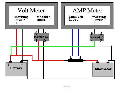
How to Wire an Auto Meter Amp Gauge - It Still Runs Auto Meter is one of the more prominent manufacturers of after-market automotive gauges. Step 1 Use the wiring diagram and test light or multi-meter to locate the positive wire from the alternator to the fuse block.

Auto meter wire diagram
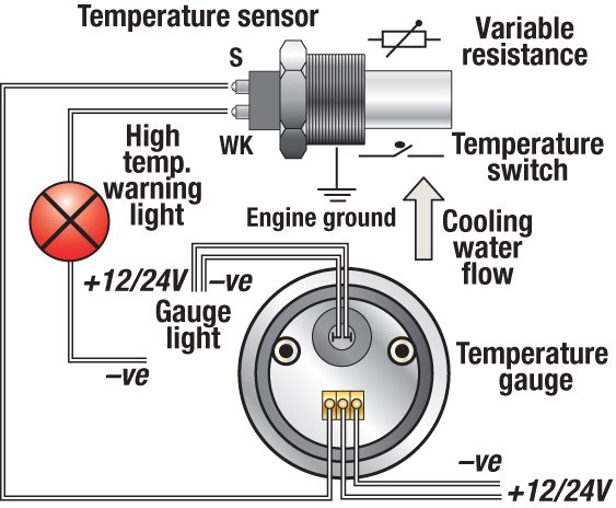
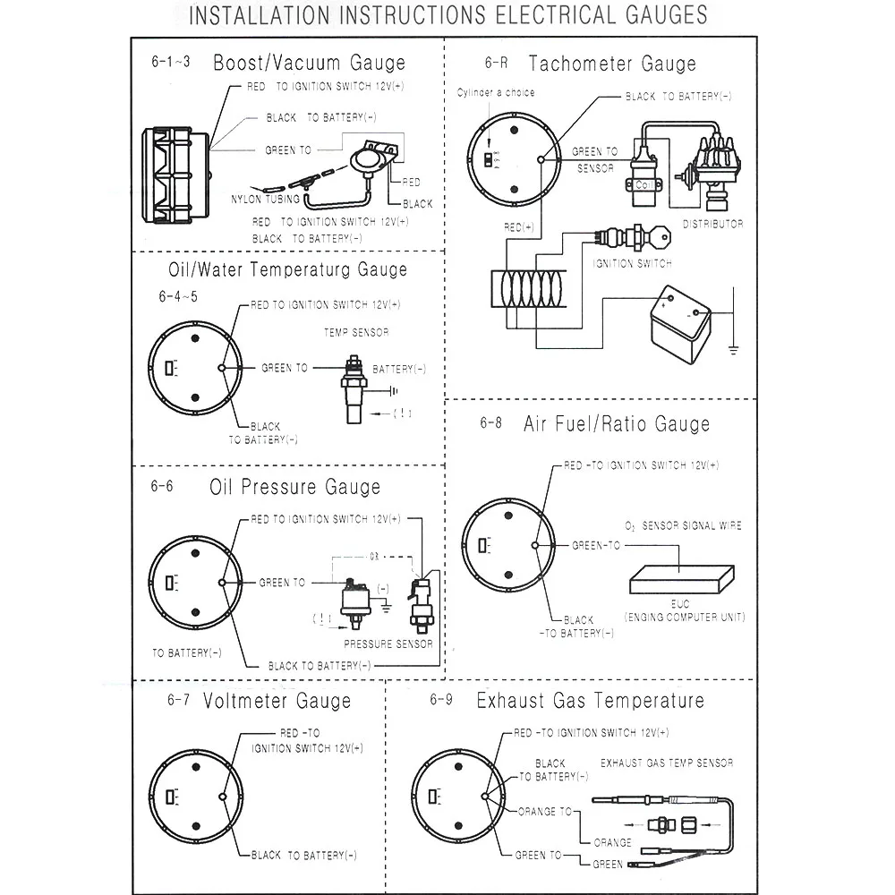
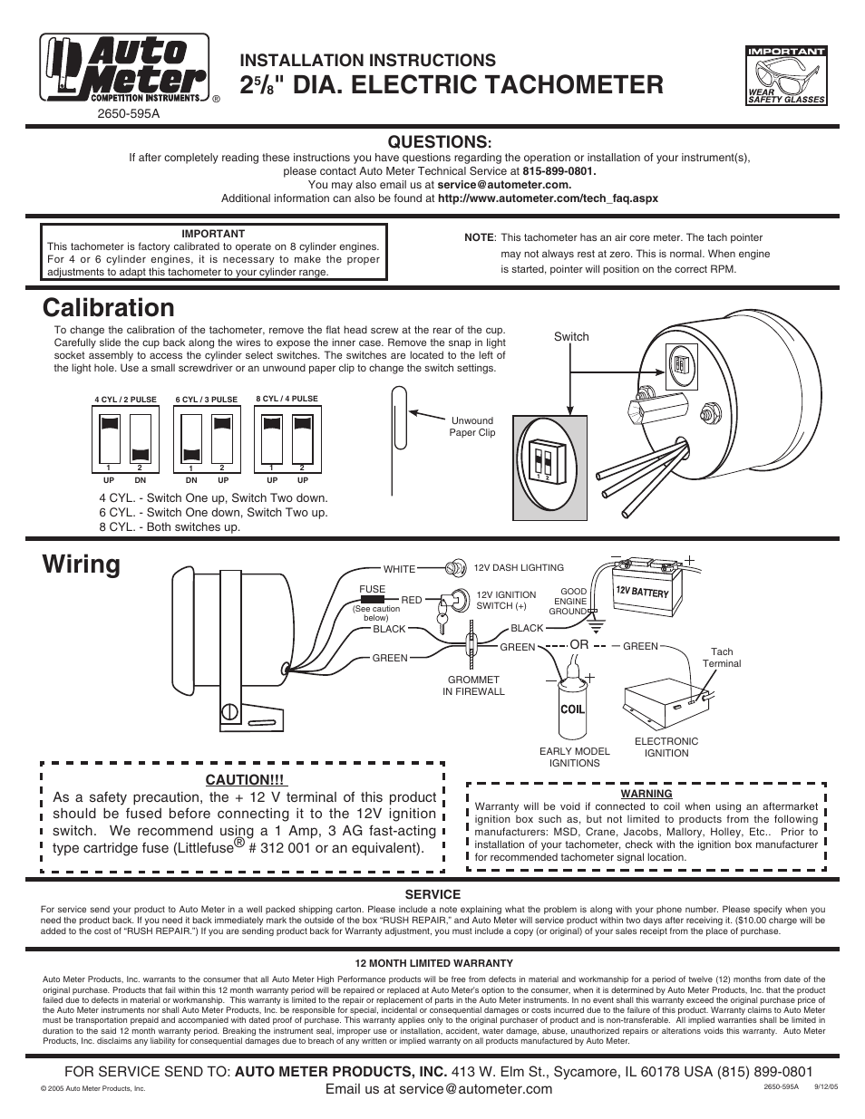
PDF Installation Instructions Electric Speedometer Recommended - Auto Meter Hall effect sender, 3-wire 16 pulses/revolution. 5291 Standard 7/8 - 18 thread 5292 Ford, plug in Mounting 1. 8Mount speedometer in a 33/ " dia. hole. Be careful not to cut the hole too large. 2. 8Cut a 3/ " dia. hole in the firewall for the speedometer wires. Place a rubber grommet in the hole and route Autometer Monster Tach Wiring Diagram - schematron.org Autometer Monster Tach Wiring Diagram 28.09.2018 2 Comments Auto Meter Pro-Comp Air-Core Pedestal Tachometer, 9k RPM, 5 Inch made by Auto Meter, for as low as $ These Pro-Comp Series Auto Meter Monster Tachs have a large 5" face for excellent visibility Tach Wiring Guide. Items Auto Meter Autogage Pedestal-Mount Tach 10, RPM with Shiftlight .. Autometer Water Temp Gauge Wiring 6 Comments. on Autometer Water Temp Gauge Wiring. Using 18 gauge wire route one length through firewall using See other side for Pressure & Temperature Gauges, and Service/Warranty information. . Breaking the instrument seal, improper use or installation, accident, water damage. Installing a tachometer or water temp gauge is a fairly easy task.
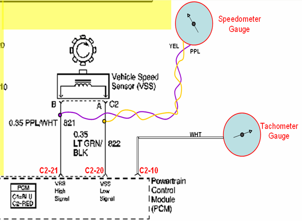
Auto meter wire diagram. Autometer Pro Shift Light Wiring Diagram - schematron.org Wiring Installation Instructions for: RPM Tachometer. 5" Spek Pro Professional Racing Gauge . Tachometer with built in shift lights for Professional Racing FOLLOW THE INSTRUCTIONS IN THE PROGRAMMING FLOW DIAGRAM TO. RPM. (36, 38, 40, 42, 44 x RPM). RPM. (46, 48, 50, 52, 54 x RPM). RPM. (56, 58, 60, 62, 64 x RPM). PDF INSTALLATION INSTRUCTIONS 5 Tachometer - Home - Autometer while FoR SERViCE SEND To: AUTO METER PRODUCTS, INC. 413 W. Elm St., Sycamore, iL 60178 USA (866) 248-6357 Email us at service@autometer.com 2650-1244-00 Rev. B 3/30/09 SERVICE For service send your product to Auto Meter Products, inc. in a well packed shipping carton. PDF Wiring Installation Instructions for : PYROMETER • sevice@autometer.com • (866) 248-6357 12 MONTH LIMITED WARRANTY Spek-Pro/Auto Meter Products, Inc. warrants to the consumer that all Auto Meter High Performance products will be free from defects in material and workmanship for a period of twelve (12) months from date of the original purchase. P0500 – Vehicle speed sensor (VSS ... - TroubleCodes.net 05/12/2015 · You can do this by touching one meter lead to the return signal pin on the sensor connector and the other to signal pin on the PCM. Set your meter to the ohms setting – you should see a value appear on the screen. If instead, your meter read OL, you have an open circuit and will need to trace the factory wiring diagram.
Autometer Trans Temp Gauge Wiring Diagram Feb 12, 2018 · Installation. WIRING. HARNESS (see diagram for details) Digital display will dim B. Trans . Autometer Egt Wiring Diagram Temp: Hole may have to be drilled, and adapter nut welded or brazed in pan. Be sure. With pressure gauges it is beneficial to add a T-fitting to install your new gauge and to keep the warning light operational. B. How to Wire an Autometer Tach - It Still Runs Step 3 Strip about 3/8 inch of insulation off the end of the red wire with wire strippers and insert the wire into a crimp-on spade connector. Crimp the connector onto the wire with a pair of crimping pliers and insert the connector into the slot you selected in the fuse box. Step 4 Autometer Oil Pressure Gauge Wiring Diagram [for oil pressure gauge installation, an optional 1⁄4" npt adapter.autometer volt gauge wiring diagram together with faria tach wiring also stewart warner gauges wiring diagrams together with auto meter wiring diagram as well as oil gauge installation along with boat navigation lights wiring diagram in addition wiring diagram for automotive … Autometer Speedometer Wiring Autometer Speedometer Wiring. INSTALLATION INSTRUCTIONS. 25/8" ELECTRIC SpEEdOmETER. Instr. No. This electric speedometer utilizes a LCD to display odometer and trip . I have an Autometer Electric Speedometer. I also have a pulse sensor from Autometer that has 5 wires (red, black, green, white and bare). INSTALLATION INSTRUCTIONS.
Auto Meter Wiring Diagram Download - Wiring Diagram Sample auto meter wiring diagram - What's Wiring Diagram? A wiring diagram is a kind of schematic which uses abstract pictorial symbols showing every one of the interconnections of components inside a system. PORSCHE - Car PDF Manual, Wiring Diagram & Fault Codes DTC PORSCHE Car Manuals PDF & Wiring Diagrams above the page - Boxster, Cayenne, Cayman, Panamera, 911 Carrera, 924, 928, 944; Porsche EWDs; PORSCHE Cars Fault Codes DTC.. The history of the German Porsche brand began in 1931 when Ferdinand Porsche, a well-known designer of the time, who worked at Auto Union and Daimler, decided to establish his own car … Autometer Sport Comp Tach Wiring - Wiring Diagrams The wiring diagram. Wiring your new Autometer tachometer into your car will complete the installation. Once you have selected a mounting location, you can run the four wires that. Wiring. The special design of the tachometer base allows for a variety of mounting For service send your product to Auto Meter in a well packed shipping carton. PDF INSTALLATION INSTRUCTIONS 3 TACHOMETER ... - Home - Autometer The wiring diagram shown is a typical installation. For Chrysler Blue, Gold and Silver Boxes, Ford Standard Electronic ... Auto Meter Products, Inc. warrants to the consumer that all Auto Meter High Performance products will be free from defects in material and workmanship for a period of twelve (12) months from date of the ...
dc-ammeter-shunt-wiring-diagram-l-fd8e3c77ca6fd112.gif (1479 ...
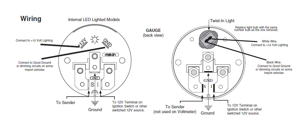
PDF Auto Meter Gauges Installation Instructions White Wire: Connect to +12 Volt Lighting. INSTALLATION INSTRUCTIONS. SHORT SWEEP ELECTRIC GAUGES. 2650-1079-00 Rev. C. Mounting. Replace light bulb with the same . number bulb as the one removed. These gauges can be mounted in-dash or in Auto Meter mounting solutions (panels, cups, pods, etc.). 2. 1 ⁄ 16" diameter gauges mount in 2. 1 ⁄ 16 ...
Troubleshooting Boat Gauges, Instruments and Meters | BoatUS
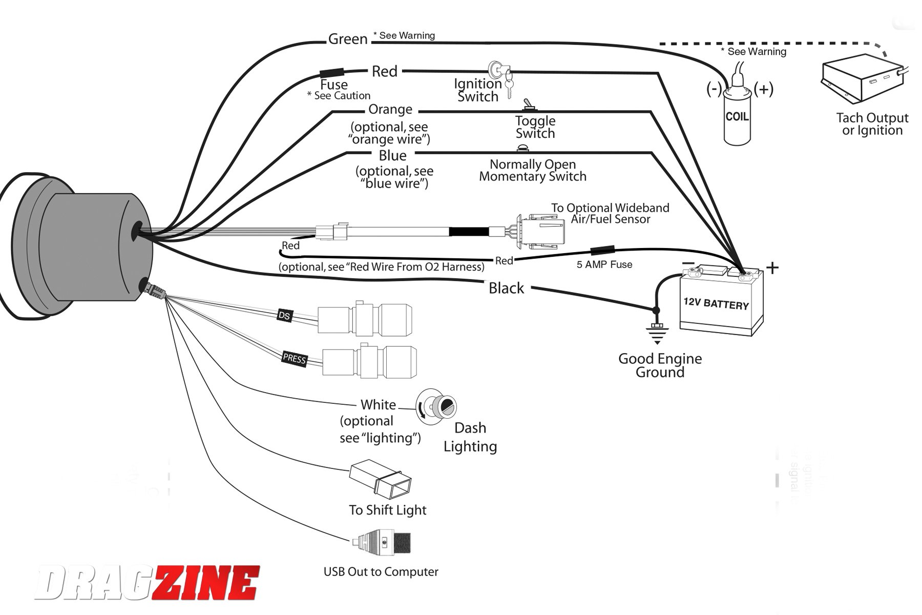
PDF UNIVERSAL GAUGE WIRE HARNESS - Autometer Basic hand tools Wire diagram for your vehicle 5A fuse & fuse holder Soldering iron, solder, various sizes of heat shrink tubing Step 1: Lay out the harness and familiarize yourself with it. You will notice not all of the terminals for the speedometer and tachometer connectors are inserted.

Auto Meter 4375 User Manual | 4 pages | Also for: 2675, 7575 ...
Autometer Shift Light Wiring Diagram - schematron.org Feb 12, 2018 · Wiring. Place switch in desired cylinder range. Red to Switched 12 Volt + Auto Meter Products, Inc. warrants to the consumer that all Auto Meter High Performance products cylinder test mode, 8 cylinder cars will light at 1⁄2 the shift RPM. AutoMeter's library of instructions ensures that you have the right installation information for your product.

AUTO METER 2198 Universal Gauge Wire Harness (for Tach/Speedo/Elec. Gauges, Incl. LED indicators)
Autometer Water Temp Gauge Wiring Diagram Autometer Water Temp Gauge Wiring Diagram See Diagram 4. Optional. Firewall. Pin Wiring. Harness & Plug. GAUGE Sensor. Water Resistant. Connector. CAUTION: 12 VOLT DC POWER relay coil when low set point (or high set point with temp gauges) of the gauge is triggered. INSTALLATION INSTRUCTIONS.
Ask Away! with Jeff Smith: Getting an Aftermarket Tach to ...
Auto Meter Prop 2 Wiring Diagram Auto Meter Wiring Diagram. 2002 Mazda B2300 Fuse Box Diagram Wiring Schematic 5291 Standard 78-18 thread 5292 Ford plug in CAUTION. Do not over tighten. Connect one end of another length of 18-gauge insulated copper wire to the center connection post as shown in Diagram 2 and the other end of the wire to a good ground source. If playback doesnt ...
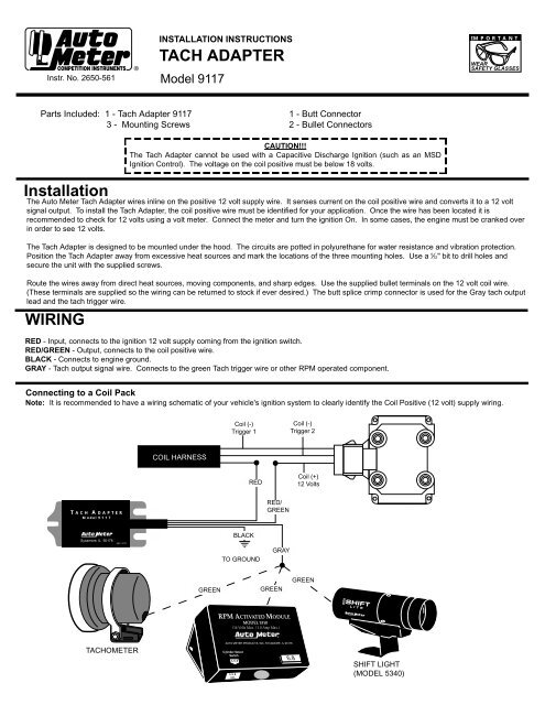
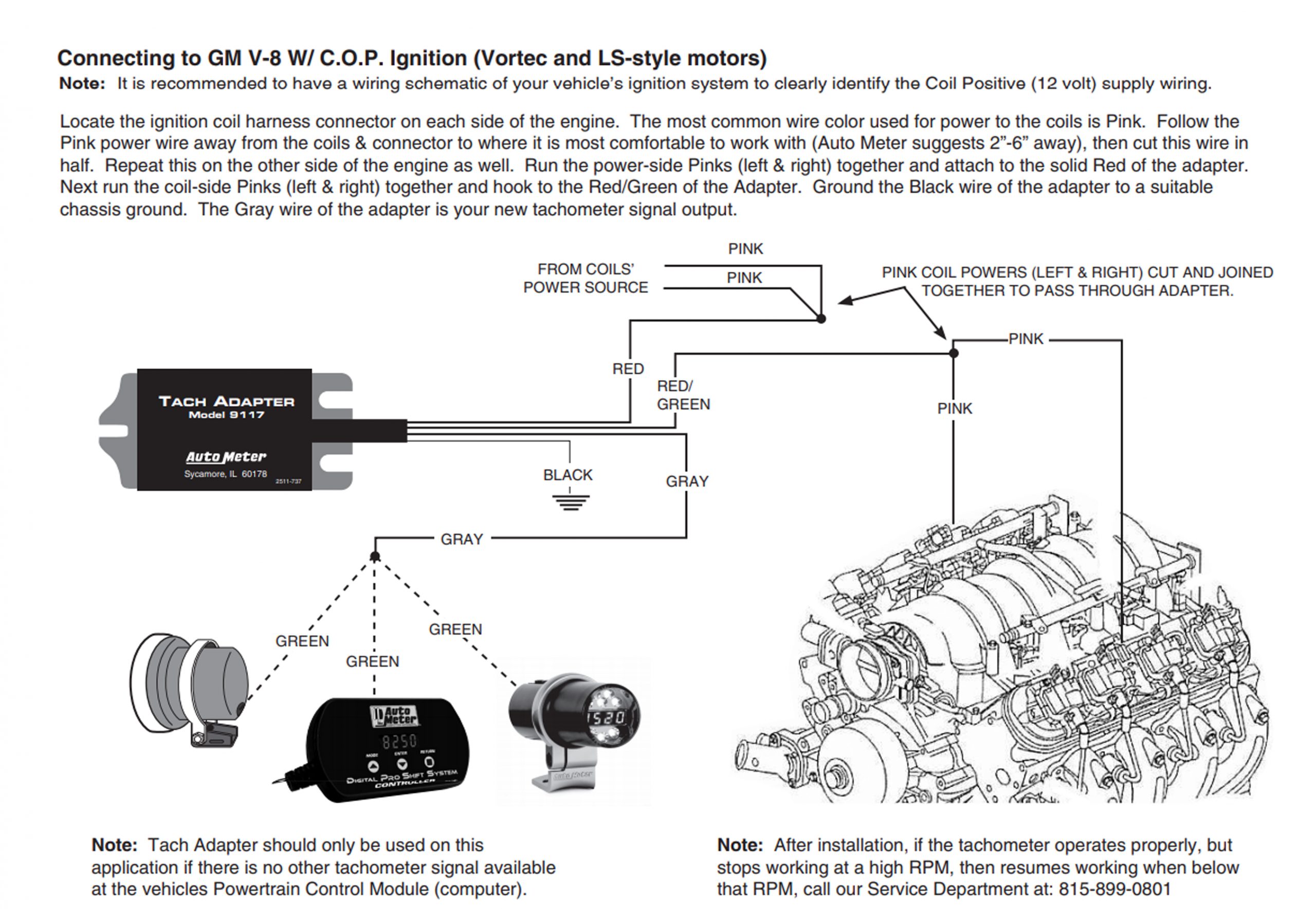
Auto Meter 9117 Tachometer Adapter Installation Instructions ...
FIAT - Car PDF Manual, Wiring Diagram & Fault Codes DTC FIAT Car Manuals PDF & Wiring Diagrams above the page - 600, Grande Punto, Uno, 500, Ducato, Scudo; FIAT Cars EWDs - 124 Spider, Cinquecento, 1500, Punto, Ducato, 500, Uno, Bravo; FIAT OBDII Fault Codes DTC.. The first car under the brand FIAT was released sometime in 1901. Designed by a talented engineer Faccioli, a car like the coach, was equipped with a 2 …
Official Website of the BCOIE Chapter
Autometer Oil Pressure Gauge Wiring Diagram Autometer Oil Pressure Gauge Wiring Diagram Autometer Oil Pressure Gauge Wiring Diagram Connect the white wire to dash lighting or switchable 12v light (see diagram for details). 6. [For oil pressure gauge installation, an optional 1⁄4" NPT adapter. So after being installed for over 3 years my oil pressure gauge stopped working. I tested.
52mm Dual Display Car Meter 7 Colors Led Air Fuel Ratio Gauge ...
Pro Comp Tach Wiring Diagram - schematron.org How to Install an Auto Meter Sport Comp 5in Tachometer w/ Shift Light on . do not connect the Blue wire as shown in the diagram in the Wiring section and only . tachometer, check with the ignition box manufacturer for 2) Pass tach wires through shock strap assembly and slide tach casing into .
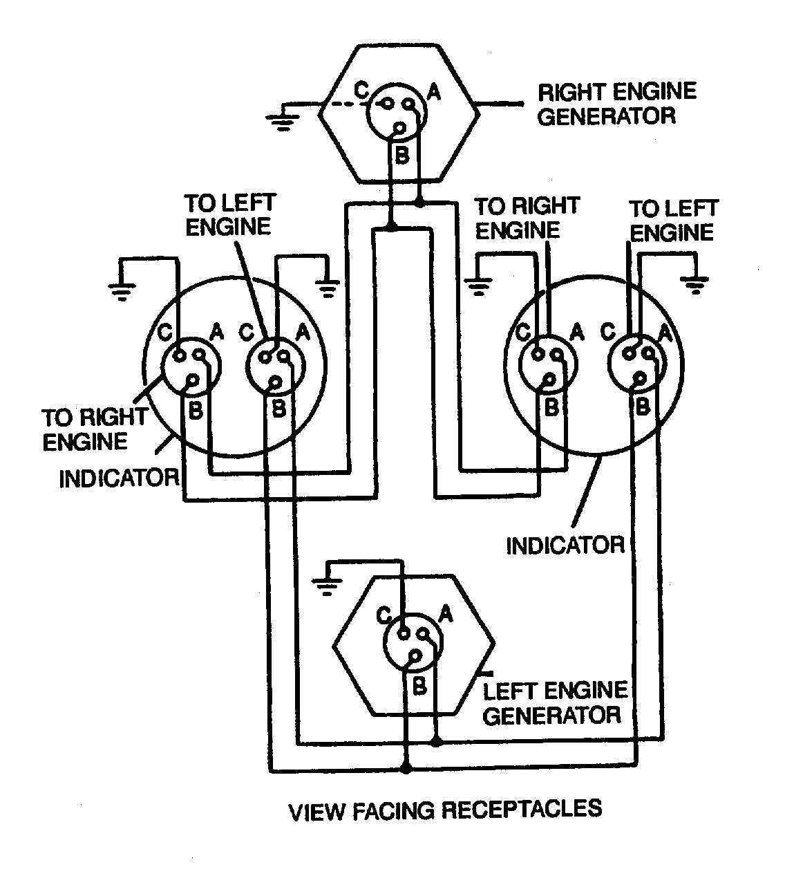
Figure 4-17. Dual Synchronous Rotor Tachometer Wiring Diagram
Autometer Sport Comp Tach Wiring Diagram Autometer Sport Comp Tach Wiring Diagram Wiring. The special design of the tachometer base allows for a variety of mounting For service send your product to Auto Meter in a well packed shipping carton. To operate the Sport-Comp Shift-Lite tachometer, first determine your desired.
Auto Meter tach wiring help | Team Chevelle
Autometer Shift Light Wiring Diagram Collection Autometer Shift Light Wiring Diagram. Effectively read a cabling diagram, one provides to know how the components within the method operate. For example , in case a module is usually powered up and it sends out a signal of 50 percent the voltage and the technician does not know this, he'd think he offers an issue, as he would expect a new 12V ...
temperature displays - Page 8
Auto Meter Pro Cycle - Instructional Downloads 2 5/8" Electric Speedometer, 3 wire with green signal wire. 2-5/8" Electric Speedometer, 4-wire with purple signal wire. 3 3/4" & 5" Electronic Speedometer. Tach/Speedo Combo.

Auto Meter Pyrometer Probe - 5251
Autometer Sport Comp Tach Wiring Diagram - schematron.org Autometer Sport Comp Tach Wiring Diagram. As a safety precaution the RED wire of this product should be fused before connecting it to the positive (+) side of switched power source. We recommend using. Any Auto Meter Shift-Lite™, or Quick-Lite™ Shift-Lite can be used with tachs 2) Pass tach wires through shock strap assembly and slide tach ...

Solar inverter Power Inverters Grid-tie inverter SolarEdge ...
PDF InVision UNIVERSAL PANEL MOUNT DIGITAL DASH - autometer.com To determine the correct wire, set your ohm meter to its lowest setting (most commonly 200, with no K or M suffix). Connect the positive lead of the meter to the wire you are going to test. Ground the meters negative lead. You are looking for something that resembles the fuel level reading you had before removing the original dash.
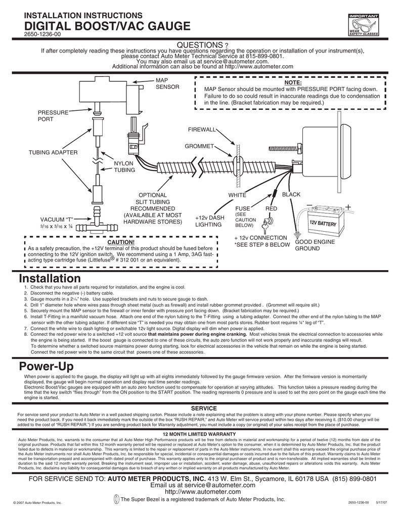
DIGITAL bOOST/vAC GAUGE INSTALLATION INSTRUCTIONS 2650-1236 ...
PDF ELECTRIC SPEEDOMETER - Home - Autometer Recommended - Auto Meter Hall effect sender, 3-wire 16 pulses/revolution. Standard 7/8 - 18 thread 5292 Ford, plug in GPS Interface Module Universal Speed Sensor 3299 Optional Tach/Speedo Gauge Connector ... Wiring - Diagram 1 SIG Engine Dash Lighting Ground GND +12V GND LAMP OUT

Auto Meter Electronic Speedometer Sending Unit (GM) Through drive for cruise control.
Autometer Water Temp Gauge Wiring 6 Comments. on Autometer Water Temp Gauge Wiring. Using 18 gauge wire route one length through firewall using See other side for Pressure & Temperature Gauges, and Service/Warranty information. . Breaking the instrument seal, improper use or installation, accident, water damage. Installing a tachometer or water temp gauge is a fairly easy task.
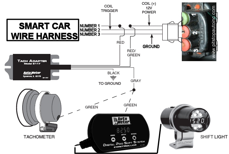
How to add an aftermarket tach to a Smart Car | Page 2 ...
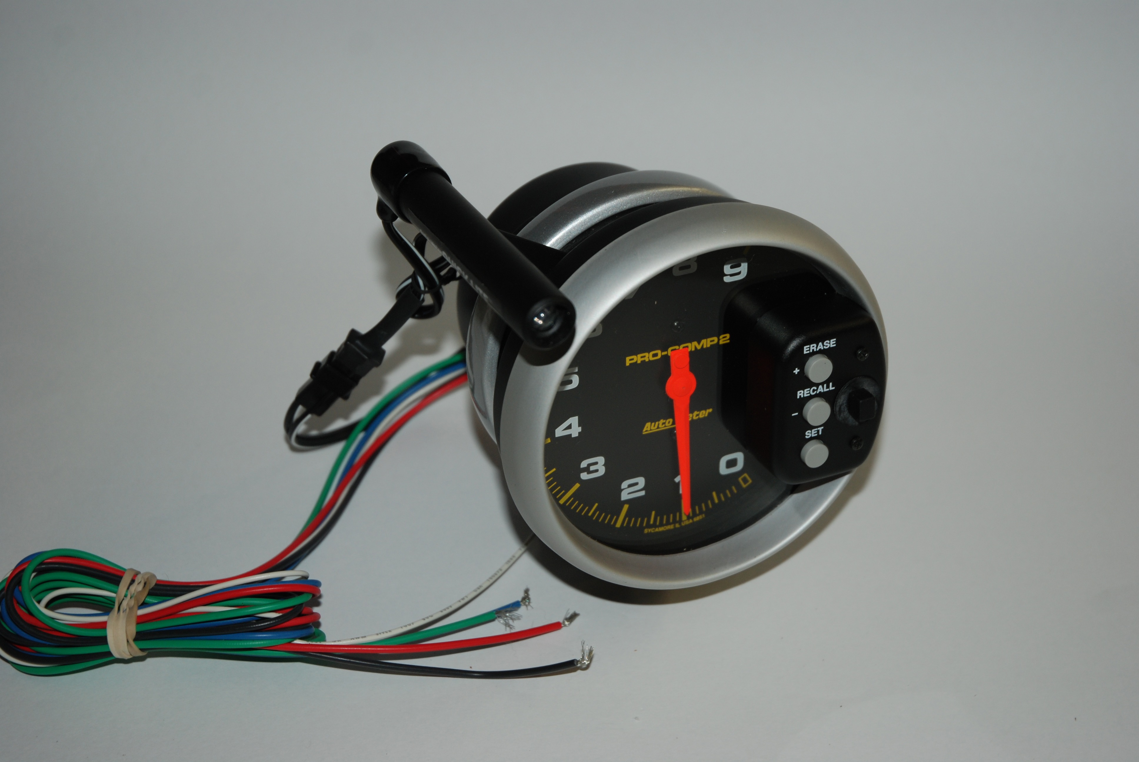
Autometer Monster Tach Wiring Diagram - schematron.org Autometer Monster Tach Wiring Diagram 28.09.2018 2 Comments Auto Meter Pro-Comp Air-Core Pedestal Tachometer, 9k RPM, 5 Inch made by Auto Meter, for as low as $ These Pro-Comp Series Auto Meter Monster Tachs have a large 5" face for excellent visibility Tach Wiring Guide. Items Auto Meter Autogage Pedestal-Mount Tach 10, RPM with Shiftlight ..
How To Install a Tachometer
PDF Installation Instructions Electric Speedometer Recommended - Auto Meter Hall effect sender, 3-wire 16 pulses/revolution. 5291 Standard 7/8 - 18 thread 5292 Ford, plug in Mounting 1. 8Mount speedometer in a 33/ " dia. hole. Be careful not to cut the hole too large. 2. 8Cut a 3/ " dia. hole in the firewall for the speedometer wires. Place a rubber grommet in the hole and route

Wiring, Jr. dragster wiring | Auto Meter 2895 User Manual ...

How do I hook up a Autometer Tach to my 2003 Chevy Cavaleir ...

Amazon.com: Auto Meter 4498 Ultra-Lite In-Dash Electric ...
Auto Meter 2893 User Manual | 1 page | Also for: 2891, 2892, 2890
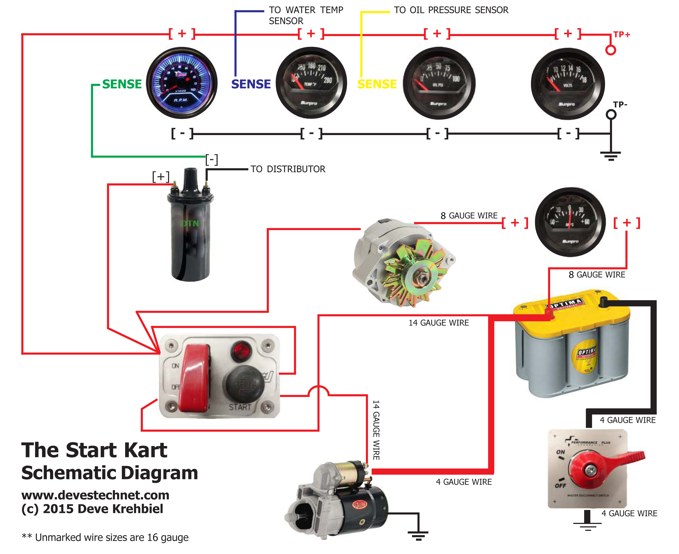
Start Kart Plans
Shifty Business: How to Install A Shift-Light Tach ...
Battery Charger Car Automotive Battery Electric Battery ...

Auto Gauge Schematic | PDF | Ignition System | Components

TAKE IT IN TOP!: Wiring Diagram for Smiths Classic Gauges
Technical - Auto meter rev control | The H.A.M.B.

UNIVERSAL GAUGE WIRE HARNESS - Auto Meter · PDF file ...
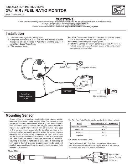
21/16" AIR / fUeL RATIO mONITOR Installation ... - Auto ...
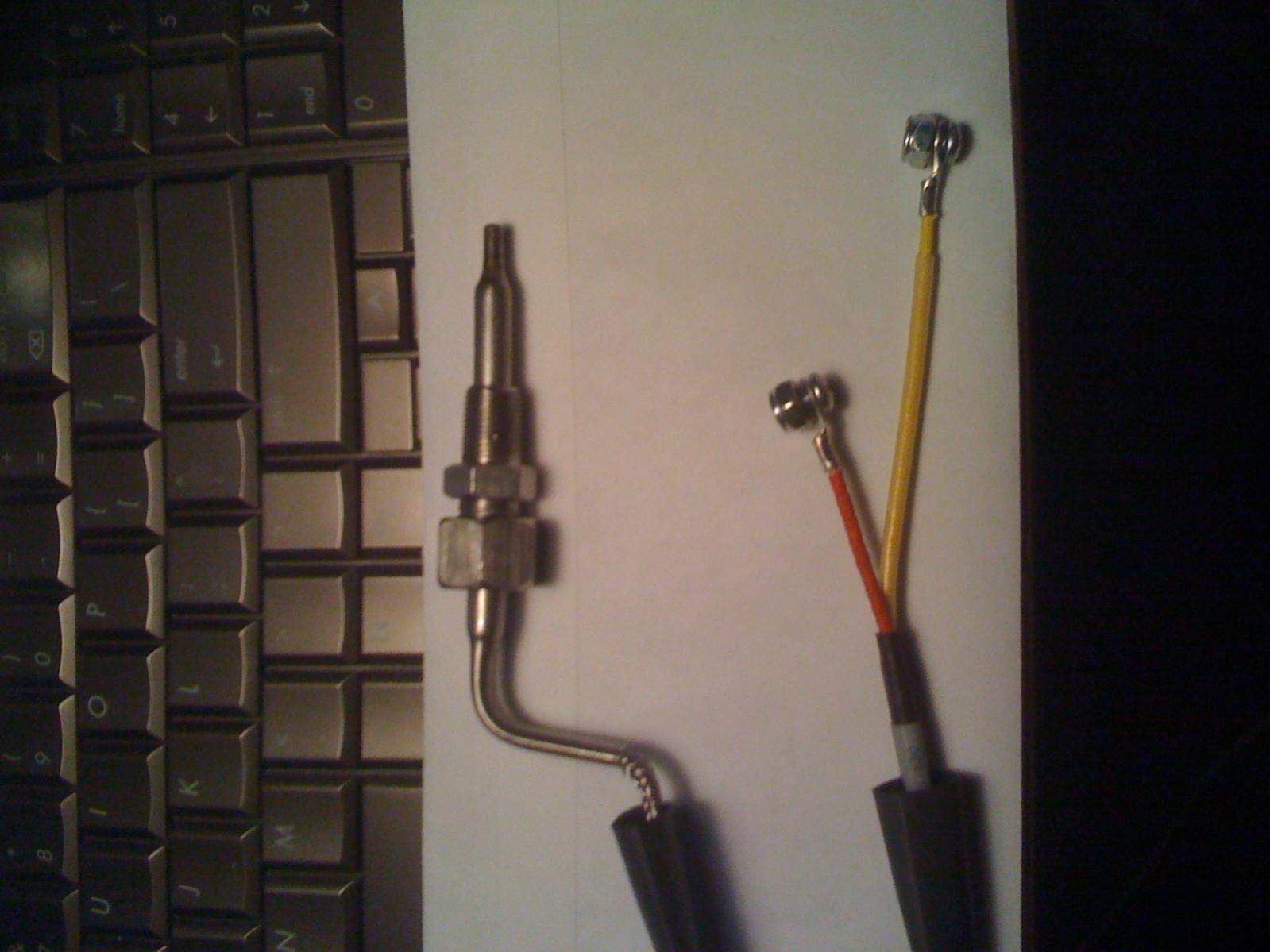
Autometer EGT pyrometer gauge intall tap size (pic) - RX7Club ...
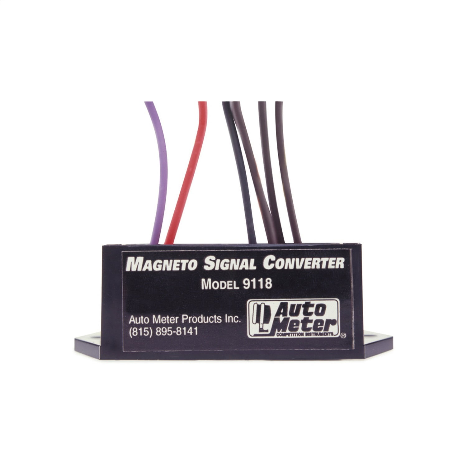
AutoMeter RPM SIGNAL ADAPTER FOR MAGNETO IGNITIONS - Walmart.com
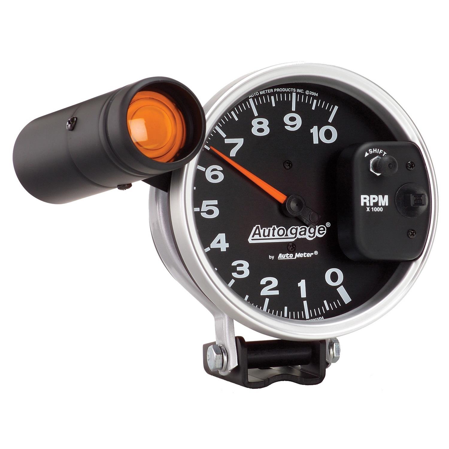
Auto gage 233904 Autogage by AutoMeter Monster Shift-Lite Tachometers | Summit Racing

DIESEL TACH ADAPTER
How to Install Auto Meter Programmable Speedometer Gauge - 0 ...
Hands-On: Effective Data Logging Through An Autometer Tachometer
Tachometer/707 question - Antique and Classic Mack Trucks ...

Classic Gauge Panel 600A Ammeter | Electric Car Parts Co
Autometer speedometer, One input terminal? - LS1TECH - Camaro ...
How to Install Auto Meter Direct Fit Dash Gauge Panel (97-06 ...
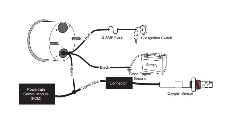
Installation Instructions for Auto Meter Cobalt Air/Fuel ...

Wiring Up A 5'' Monster Tacho In Your Car - Car Electrical ...
0 Response to "41 auto meter wire diagram"
Post a Comment