38 eaton contactor wiring diagram
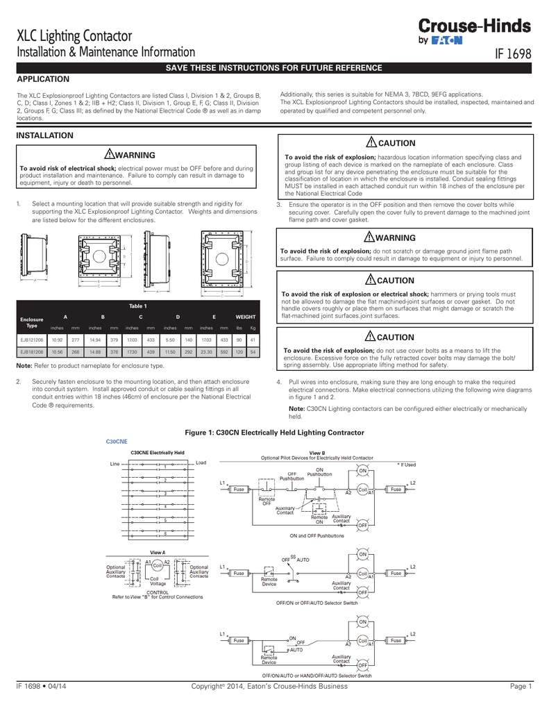
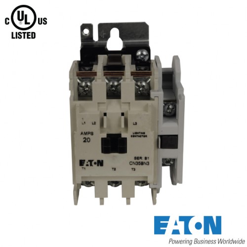
Eaton Cn35 Lighting Contactor Wiring Diagram | Shelly Lighting Eaton Cn35 Lighting Contactor Wiring Diagram Shelly Lighting September 23, 2018 Lighting contactors eaton cutler hammer lighting contactors mechanically held lighting contactors volume 10 tab 4 Eaton Contactor Wiring Diagram - Wiring Diagram Line Eaton Contactor Wiring Diagram. By Tisha Setty | February 23, 2019. 0 Comment. C30cn lighting contactors instruction sheet volume 10 tab 4 c25dnd330a eaton cutler hammer contactor 30 a panel mount moeller xtot630c3s cur transformer operated overload relay and starters 30cn mechanically held i have an 20amp catalog cn35bn3ab 3 pole it was ...
Contactor Wiring Diagram Underfloor Heating 5 . a contactor or similar device will be required. Download and Read Wiring Diagram For Underfloor Heating Wiring Wiring Diagram For Contactor Underfloor Heating - diagramweb.net whenever the heating load exceeds 12 Amps (75% of the rated capacity of 16 A). When wiring to a contactor, the Active output of the thermostat ("L Load".
Eaton contactor wiring diagram
2 Pole Contactor Wiring Diagram - easywiring The above diagram is a complete method of single phase motor wiring with circuit breaker and contactor. As you know that we use the double pole mcb circuit breaker as main circuit breaker in our single phase distribution board. 2 pole contactor wiring diagrams data. Mechanically latched contactors 18 class 8196 18 medium voltage. Contactor Wiring Diagram - Wiring Diagram How To Wire A Contactor: 8 Steps (With Pictures) - Wikihow - Contactor Wiring Diagram. Wiring Diagram comes with several easy to adhere to Wiring Diagram Directions. It's meant to aid all of the typical consumer in building a correct method. These guidelines will likely be easy to grasp and implement. Eaton Contactor Wiring Diagram - Irish Connections Eaton Contactor Wiring Diagram. By Irish Bella | July 16, 2018. 0 Comment. C30cn lighting contactors instruction sheet volume 10 tab 4 freedom reversing contactor nema size wiring diagram eaton moeller zw7 125 cur transformer operated overload relay c25dnf340a cutler hammer 40 a panel mount and starters 30cn mechanically held i have an 20amp ...
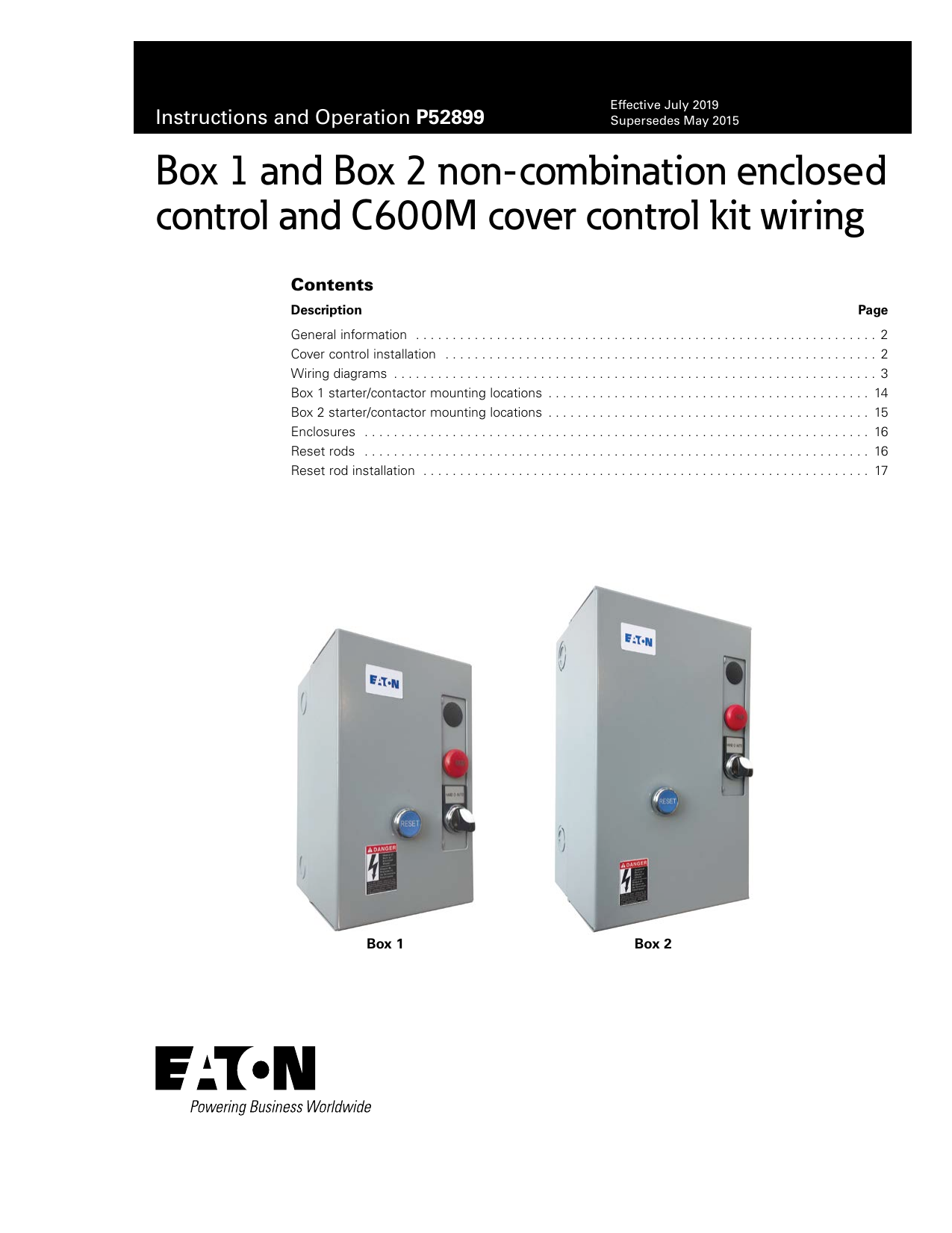
Eaton contactor wiring diagram. PDF Basic Wiring for Motor Contol - Eaton Wiring diagrams show the connections to the controller. Wiring diagrams, sometimes called "main" or "construc-tion" diagrams, show the actual connection points for the wires to the components and terminals of the controller. They show the relative location of the components. They can be used as a guide when wiring the controller. Figure 1 (PDF) eaton-motor-control-basic-wiring.pdf | Dominic Jay ... Common vs. Separate Control TD03309004E For more information visit: Technical Data Basic Wiring for Page 6 Effective: April 2007 Motor Contol Circuitry of a Starter Two-Wire Control Two-Wire Control circuits — or Low Voltage Release One of the common control wiring circuits used is known as 1/ 3/ 5/ L1 L2 L3 Two-Wire or Low ... Eaton Magnetic Starter Wiring Diagram - U Wiring Contactor Wiring Diagram With Timer New Eaton Contactor Wiring Diagram Wiring Diagrams Schematic Well Pump Pressure Switch Diagram Wire Typical Wiring Diagram Line diagrams show circuits of the operation of the. Eaton magnetic starter wiring diagram. Basic wiring for motor control 36326 ads8 brochure eaton cutler hammer magnetic switch. Eaton C25DND330 definite purpose contactor | 3 pole 30 AMP C25DND330. Eaton / Cutler Hammer C25DND330 definite purpose contactor that has three poles, is rated for 30 AMPS and has an AC rated coil (must specify voltage below). These DP contactors have double quick connect terminals and mount via a standard metal base plate. Side mounted auxiliary contacts can be added to the C25DND330 and it is a ...
Peerless Mechanically Held Contactor Wiring Diagram 3 ... Contactor Wiring Diagram With Timer Unique Eaton Diagrams Schematic Single Pole Light Switch Neon Indicator Led For Trailer Lights. Unique Wiring Diagram For Mechanically Held Lighting Contactor Wire Air Compressor 240v Counterpoise Earthing Drawing. Click on the image to. Mechanically held contactor wiring diagram. Diagram seagull led under ... Eaton Definite Purpose Contactor Wiring Diagram - 29 3 Pole Contactors C25dnf240t Eaton C25bnb230a Compact Definite Purpose Contactor 30a Eaton Cutler Hammer C25dnf240b Contactor 2 Pole 40 Amp 240 Vac Coil C1 Dc Contactor Wiring Wiring Diagram 500 Definite Purpose Dp Contactors Eaton Eaton C25cnb130t Definite Purpose Contactor Type C25 1 Pole Xtce009b10td Contactor For Double Pole Wiring Diagram ... Eaton Light Switch Wiring Diagram - U Wiring Eaton Wiring 15 Amp Rocker Switch Single Pole 2 3 Way 120v White 7728w. Diagram Eaton Transformer Wiring Full Version Hd Quality Outletdiagram Romanicolecco It. Eaton 15 Amp 3 Way Light Switch White Csb315Stw Sp The Home Depot Single Pole Light Switch Wiring Diagram Uploaded by Anna R. Eaton Wiring 15 Amp Toggle Switch. Contactor Coil Wiring Diagram - The Wiring A wiring diagram is a simplified traditional pictorial representation of an electrical circuit. These voltages must be electrically isolated from the standard 120 volts AC. A direct online starter consits of two buttons, a GREEN button for starting and a RED for stopping purpose of the motor. Single phase reversing contactor wiring diagram.
Definite Purpose (DP) Contactors - Eaton - YouTube Definite Purpose Starters are electrically operated switching devices specifically designed for the heating, ventilation, air conditioning and refrigeration ... 240 Volt Contactor Wiring Diagram - Wiring Diagram Wiring Diagram contains each illustrations and step-by-step guidelines that might enable you to really construct your venture. This really is useful for the two the people and for experts who are seeking to learn more on how to set up a operating environment. Wiring Diagrams are designed to be easy to understand and easy to construct. Timer And Contactor Wiring Diagram Pdf - Wiring Diagram Pdf contactor wiring diagram with timer. The diagram symbols in table 1 are used by square d and where applicable conform to nema national electrical manufacturers a ssociation. Otherwise the arrangement wont function as it. Contactor breakers limit switch no static control standard elementary diagram symbols. Eaton XTCE015B10 Series Contactor - Klockner Moeller EATON XTCE015B10 Series Contactor: Ie [A] HP : Auxiliary Contacts : AC-3 : AC-1 @ 230 @ 460 : Normally Open : Normally Closed : 15: 18: 5: 10 : 1 : 0 : Eaton XTCE015B10 Ordering Information
PDF Contents IEC Contactors & Starters - Carlton Bates An E501F(140 mm) consists of two E111F(Contactors), an E06NF(Reversing Overload Relay), Mechanical Interlock, Crossover Bus Bars and Reversing Wiring Harness. Consult Factory for 27 mm A-Frame Reversing Starters, 6A - 12A. See Table 34-9for 24V DC power supply requirements. Control inputs are rated 24V DC (3 - 5 mA).
Simple Mechanically Held Lighting Contactor Wiring Diagram Contactor Wiring Diagram With Timer Unique Eaton Diagrams Schematic Forward Reverse Circuit Ge Electric Motor Parts. Mechanically held lighting contactor wiring diagram print the cabling diagram off in addition to use highlighters in order to trace the routine.
eaton motor starter wiring diagram - Wiring Diagram and ... Eaton Motor Starter Wiring Diagram . July 29, 2019 1 0 . Basic wiring for motor control circuit diagram pdf weldingweb welding community pros contactors and starters 36326 ads8 brochure magnetic starter advice doityourself galaxysweetflower 3p electronic overload 120vac coil freedom nema ... Manual Motor Starters Contactors And Eaton

Eaton C25BNF240A Compact Definite Purpose Contactor, 40A Inductive Current Rating, 3 Max HP Rating at 115V, 7.5 Max HP Rating at 230V, 120VAC Coil ...
Eaton Switch Wiring Diagram - Diagram Sketch Eaton Switch Wiring Diagram. Tork Wiring Schematic For Lighting Contactor And Photocell In 2021 Porch Light Timer Light Switch Wiring Porch Lighting. Eaton Br 100 Amp 2 Pole Circuit Breaker Br2100cs The Home Depot Home Electrical Wiring Breakers Electrical Panel Wiring.
Eaton Lighting Contactor Wiring Diagram | vincegray2014 Eaton Lighting Contactor Wiring Diagram Free Download 2022 by abby.kulas. Find The BestTemplates at vincegray2014.
Contactor And Relay Wiring Diagram - The Wiring Wiring Diagram for Telemecanique LC1 Contactor Replacements by US Breaker LR Aux NC1D Aux NC1D Aux-m Control supply voltage is the same as the main circuit voltage (3 phase) Control supply voltage is not the same as the main circuit voltage (3 phase) Connect to other supply Control supply voltage is the same A wiring diagram is a simplified traditional photographic depiction of an electrical circuit.
PDF Contents Lighting Contactors - Newark This device mounts on top of any side mounted auxiliary contact on lighting contactors 100 - 300A. It connects across coil terminals on any 120V con- tactor magnet coil. Limits high voltage transients pro- duced in the circuit when power is removed from the coil. Table 37-2. Kits for 100 - 300A
How to Wire a Contactor: 8 Steps (with Pictures) - wikiHow Energize the contactor. Apply the control voltage to the input. Listen for the contactor to click as it engages. De-energize the contactor. 8 Connect the outputs. Put the stripped end of each wire into the appropriate contact block after loosening the screw of the block. Make sure that no stray strands of wire are jutting from the contact blocks.
How to wire a contactor and overload - Direct Online ... 4:27. How to wire contactor and motor protection switch - Direct On Line Starter. 6:55. Wiring star-delta motor starter. Power and control circuit. 4:34. How to wire Phase Failure Relay. 4:10 ...
Auxiliary Contactor Wiring Diagram - My Wiring Info Collection of eaton lighting contactor wiring diagram. Instead, it should be rated at 120 volts AC. Variety of definite purpose contactor wiring diagram. ON / OFF ThreePhase Motor Connection Power & Control . 14 Pin Relay Wiring Diagram Topic Aux Fuse Box Wiring . How To Wire A Room In House Diagram, Electrical circuit
PDF Lighting contactors (open) - Eaton Contactors from Eaton's Electrical Sector are designed for industrial, commercial and outdoor lighting applications where efficient control is required. The mechanically held operation ensures that the contactor will not switch to OFF during control power failure. It also ensures the removal of coil from the circuit for noise-free operation and
Eaton Contactor Wiring Diagram - Irish Connections Eaton Contactor Wiring Diagram. By Irish Bella | July 16, 2018. 0 Comment. C30cn lighting contactors instruction sheet volume 10 tab 4 freedom reversing contactor nema size wiring diagram eaton moeller zw7 125 cur transformer operated overload relay c25dnf340a cutler hammer 40 a panel mount and starters 30cn mechanically held i have an 20amp ...
Contactor Wiring Diagram - Wiring Diagram How To Wire A Contactor: 8 Steps (With Pictures) - Wikihow - Contactor Wiring Diagram. Wiring Diagram comes with several easy to adhere to Wiring Diagram Directions. It's meant to aid all of the typical consumer in building a correct method. These guidelines will likely be easy to grasp and implement.
2 Pole Contactor Wiring Diagram - easywiring The above diagram is a complete method of single phase motor wiring with circuit breaker and contactor. As you know that we use the double pole mcb circuit breaker as main circuit breaker in our single phase distribution board. 2 pole contactor wiring diagrams data. Mechanically latched contactors 18 class 8196 18 medium voltage.


0 Response to "38 eaton contactor wiring diagram"
Post a Comment