41 fe-c phase diagram
PDF APPLICATIONS OF Fe-C PHASE DIAGRAM KEY POINTS OF Fe-C Diagram Phases: •Liquid Fe-Tmin=1148C @ 4.3%C •1394 C<δ-Fe-<1538C •α-Ferrite (Ferrite)<912C; <0.02%C •Magnetic-nonmagnetic-770C PDF Chapter Outline: Phase Diagrams MSE 2090: Introduction to Materials Science Chapter 9, Phase Diagrams 2 Component - chemically recognizable species (Fe and C in carbon steel, H2O and Sucrose in sugar solution in water). A binary alloy contains two components, a ternary alloy - three, etc. Phase - a portion of a system that has uniform physical and chemical characteristics ...
en.wikipedia.org › wiki › Phase_diagramPhase diagram - Wikipedia A phase diagram in physical chemistry, engineering, mineralogy, and materials science is a type of chart used to show conditions (pressure, temperature, volume, etc.) at which thermodynamically distinct phases (such as solid, liquid or gaseous states) occur and coexist at equilibrium
Fe-c phase diagram
The Iron-Carbon Alloys And Fe-C Phase Diagram - MechanicalBase What Is Iron-Carbon Phase Diagram? Iron-Carbon (Fe-C) phase diagram. The iron-carbon phases and phase diagram is slightly complex, compared with other diagrams. The horizontal axis of the Fe-C diagram shows the percentage of carbon inside the Fe-C systems. The solubility limit of carbon inside the iron is very low. Thermodynamics and phase diagram of the Fe-C system ... A critical review of published data provides a fairly accurate knowledge of the thermodynamic properties of all of the phases of the system Fe-C that are stable or metastable at atmospheric pressure. Selected data are shown as tables and equations. A proposed phase diagram differs only slightly from others recently published but has the following features. Peritectic compositions and the α-γ ... fractory.com › iron-carbon-phase-diagramIron-Carbon Phase Diagram Explained [with Graphs] - Fractory The boundaries, intersecting each other, mark certain regions on the Fe3C diagram. Within each region, a different phase or two phases may exist together. At the boundary, the phase change occurs. These regions are the phase fields. They indicate the phases present for a certain composition and temperature of the alloy.
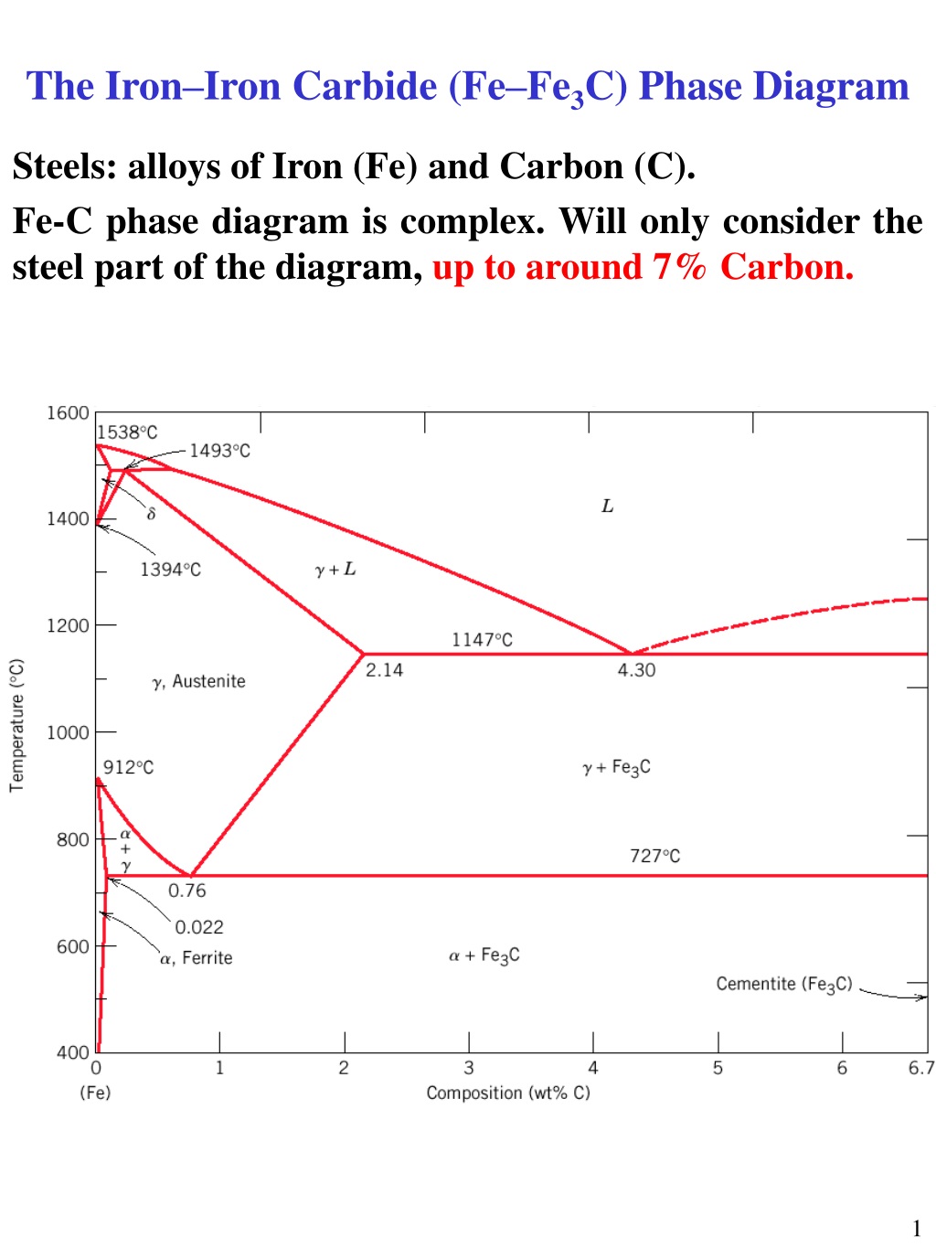
Fe-c phase diagram. Fe-C Phase Diagram | PDF | Heat Treating | Hardness The Iron-Iron Carbide (Fe-Fe3C) Phase Diagram In their simplest form, steels are alloys of Iron (Fe) and Carbon (C). The Fe-C phase diagram is a fairly complex one, but we will only consider the steel part of the diagram, up to around 7% Carbon. University of Tennessee, Dept. of Materials Science and Engineering 2 Computer calculations of metastable and stable Fe-C-Si ... Computer calculations of metastable and stable Fe-C-Si phase diagrams from binary thermodynamic properties Computer calculations of metastable and stable Fe-C-Si phase diagrams from binary thermodynamic properties. Download File. r_8627100.pdf (1004.34 KB) Date. 1986. Authors. Chueh, Shan-Chang. Journal Title. Journal ISSN. The Iron-Carbon Phase Diagram - IspatGuru The study of the constitution and structure of iron and steels starts with the iron-carbon (Fe-C) phase diagram (Fig 1). Fe-C phase diagram is also used as the basis for the understanding of the heat treatment processes. Many of the basic features of Fe-C system influence the behaviour of even the most complex alloy iron and steels. Fe-C Phase Diagram Flashcards | Quizlet 3 phases on a Fe-C phase diagram. austenite (gamma phase), ferrite (alpha phase), and cementite (Fe3C) what are the two types of nucleation and growth. homogeneous and heterogeneous. properties of martensite. hard and brittle (rapid cooling, quenching) 3 broad categories of phase transforms.
Fe-C diagram - SlideShare Phases Observed in Fe-C Diagram • Phases 1. Ferrite 2. Austenite 3. Cementite 4. δ-ferrite • And phase mixtures 1. Pearlite 2. Ledeburite 6. Phases Observed in Fe-C Diagram 1. Ferrite Ferrite is the interstitial solid solution of carbon in alpha iron. It has B.C.C. Structure. eng.utq.edu.iq › sites › 4/2019/09The Iron Carbide (Fe Fe3C) Phase Diagram C Phase Diagram ¾α‐ferrite‐solid solution of C in BCC Fe •Stable form of iron at room temperature. • Transforms to FCC g‐austenite at 912 °C ¾γ‐austenite‐solid solution of C in FCC Fe • Transforms to BCC δ‐ferrite at 1395 °C •Is not stable below the eutectic temperature (727 °C) Example T_03 - Fe-C Phase Diagram - YouTube Learn two simple ways to calculate a binary phase diagram in the Fe-C system using the graphical mode of Thermo-Calc. ~~TIMESTAMPS~~0:00 Intro0:42 How to cal... Fe-C phase diagram (CALPHAD.com). | Download Scientific ... Download scientific diagram | Fe-C phase diagram (CALPHAD.com). from publication: Thermophysical properties and structure of liquid Fe-C alloys | The paper reports experimental data on density and ...
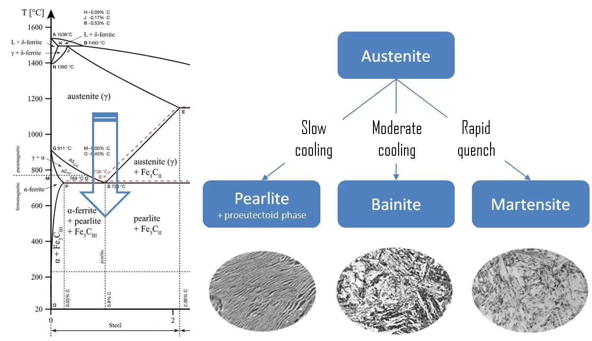
› academic-files › ArabicIRON CARBON PHASE DIAGRAM transformation in relation to Fe-C diagram In order to understand the transformation processes, consider a steel of the eutectoid composition. 0.8% carbon, being slow cooled along line x-x'. At the upper temperatures, only austenite is present, with the 0.8% carbon being dissolved in solid solution within the FCC. When the steel cools through ... The Fe-Cr-C ternary phase diagram (a) Liquidus projection ... Download scientific diagram | The Fe-Cr-C ternary phase diagram (a) Liquidus projection and (b) at 870 ° C. from publication: Microstructural evolution with various Ti contents in Fe-based ... Fe-C diagram - Physics Forums Fe-C phase diagram Can someone explain to me what happens in the Fe-C phase diagram during cooling from melt to room temperature when the content of C is 0,2%? All those lines in the diagram confuse me a bit... :grumpy: What I don't get is how I can say anything about what happens in room... phase diagram iron carbon - Metallurgy for Dummies The cast iron portion of the Fe-C phase diagram covers the range between 2.08 and 6.67 wt. % C. The steel portion of the metastable Fe-C phase diagram can be subdivided into three regions: hypoeutectoid (0 < wt. % C < 0.68 wt. %), eutectoid (C = 0.68 wt. %), and hypereutectoid (0.68 < wt. % C < 2.08 wt. %).
Solved The phase diagram of Iron – Carbon: Consider a 94 ...
PDF Iron-Carbon Phase Diagram (a review) see Callister Chapter 9 The Iron-Iron Carbide (Fe-Fe3C) Phase Diagram In their simplest form, steels are alloys of Iron (Fe) and Carbon (C). The Fe-C phase diagram is a fairly complex one, but we will only consider the steel part of the diagram, up to around 7% Carbon.
phase diagram iron carbon | Metallurgy for Dummies
Iron-Carbon Diagram Explanation [PDF] - Mechanical E-Notes Iron-Carbon Phase Diagram with Detailed Explanation: If the percentage of the carbon is in the range of 0 to 2.11 % then it is called Steel and if the percentage of carbon is in the range of 2.11 to 6.67% then it is called Cast iron. As the carbon content increases, it produces more Iron-Carbide volume and that phase will exhibit high hardness.
![The Iron - Iron Carbide (Fe-Fe C) Phase Diagram - [PDF Document]](https://reader020.staticloud.net/reader020/html5/20190923/5891a0c41a28ab26788b56e8/bg1.png)
The Iron - Iron Carbide (Fe-Fe C) Phase Diagram - [PDF Document]
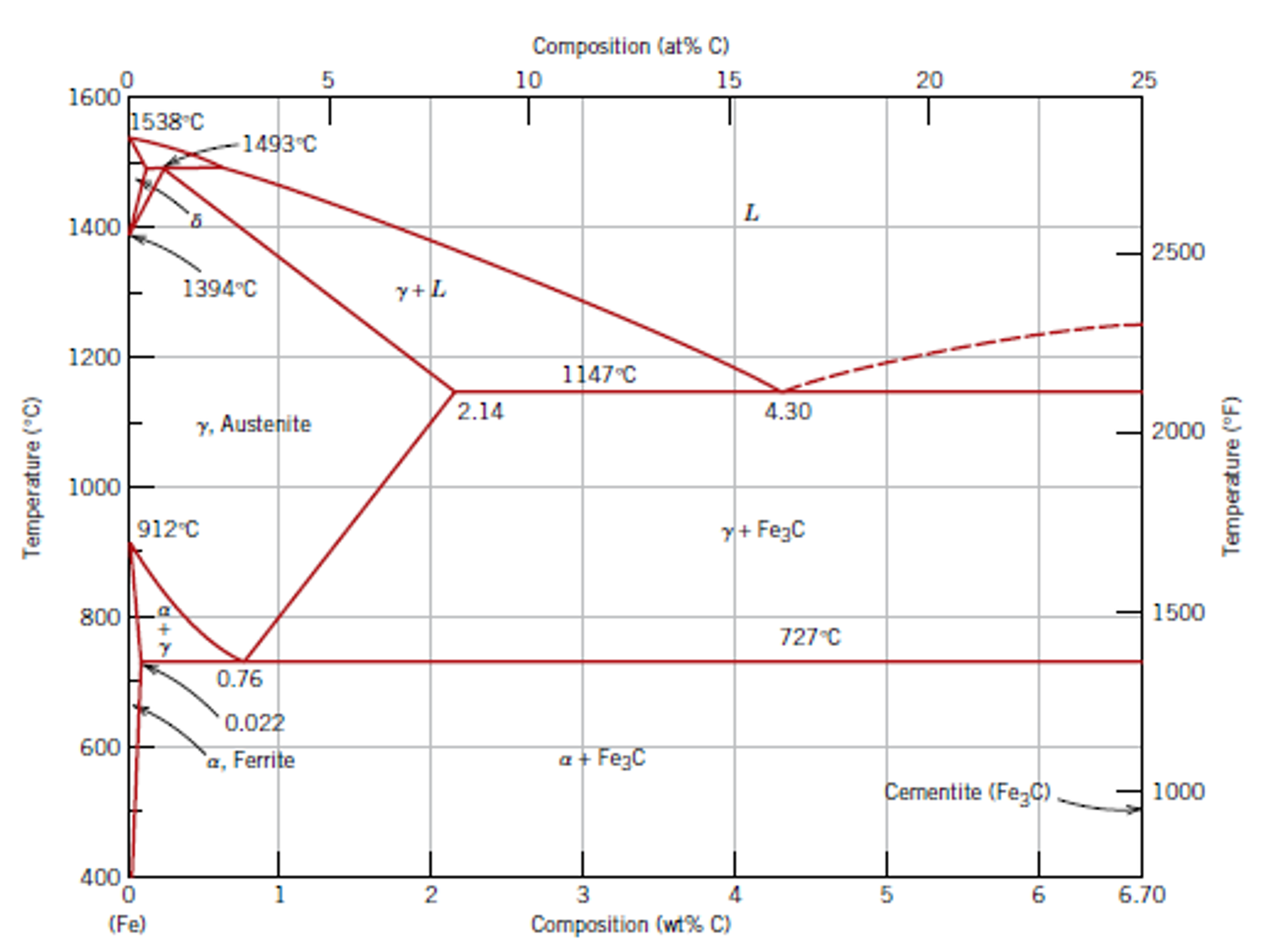
PDF The C-Fe (Carbon-Iron) System - gotrawama.eu 1 Assessed Fe-C phase diagram from 0 to 25 aL% Fe. Stable Fe-C (graphite) and metastable Fe-Fe3C (cementite) equilibria.
IRON-CARBON (Fe-C) PHASE DIAGRAM - ppt download
PDF Iron-Iron carbide (Fe-Fe C) Phase Equilibrium Diagram C) Phase Equilibrium Diagram In this diagram weight % C is plotted along horizontal axis and temperature along vertical axis. The diagram shows the phases present at various temperatures for very slowly cooled Fe-C alloys with carbon content up to 6.67%. Information given by the diagram: 1. Solid phases in the phase diagram 2. Invariant ...

File:Steel Fe-C phase diagram-en.png - Wikipedia
Thermodynamic description of the Fe-Cu-C system ... In the present study, the Fe-C phase diagram is optimized on the basis of Gustafson's results [10]. Therefore, only the parameters of the liquid phase were slightly modified, while those of the fcc and bcc phases remain the same as Gustafson's [10]. As for the metastable phase, optimized results by Göhring [17] were adopted.

4 Fe-C phase diagram and the vertical line showing DP-600 ...
Answered: (a) The Fe-C phase diagram is show in… | bartleby (a) The Fe-C phase diagram is show in Figure Q5(a). Answer the following questions based on the phase diagram. (i) The microstructure of an iron-carbon alloy consists of proeutectoid ferrite and pearlite; the mass fraction of these two phases are 0.28 and 0.72, respectively.
The iron-iron carbide (Fe-Fe3C) phase diagram Microstructures ...
› ternary-phase-diagramTernary Phase Diagram - an overview | ScienceDirect Topics 2.3.5.5.3 Fe–C–S System. Ohtani and Nishizawa calculated the Fe–C–S ternary phase diagram on the basis of the thermodynamic analysis of Fe–C and Fe–S and Fe–C–S ternary melts [203]. The Gibbs free energy of individual phases was approximated by the interstitial solution model, assuming both C and S to be interstitial atoms.
Phase Diagrams of Iron-carbon System | nuclear-power.com
Fe-C phase diagram - YouTube Fe-C phase diagram
![Iron-Carbon Phase Diagram Explained [with Graphs]](https://fractory.com/wp-content/uploads/2020/03/Iron-carbon-phase-diagram-explained.jpg)
Iron-Carbon Phase Diagram Explained [with Graphs]
sig.ias.edu › files › Ternary Phase DiagramsTernary Phase Diagrams - Institute for Advanced Study For “normal diagrams”, where interested in all . components, use the . Normal equilateral . triangle. For diagrams where there is a major . component, e.g. Fe in Fe-C-Cr, use a

Please answer the following question regarding the iron-iron ...
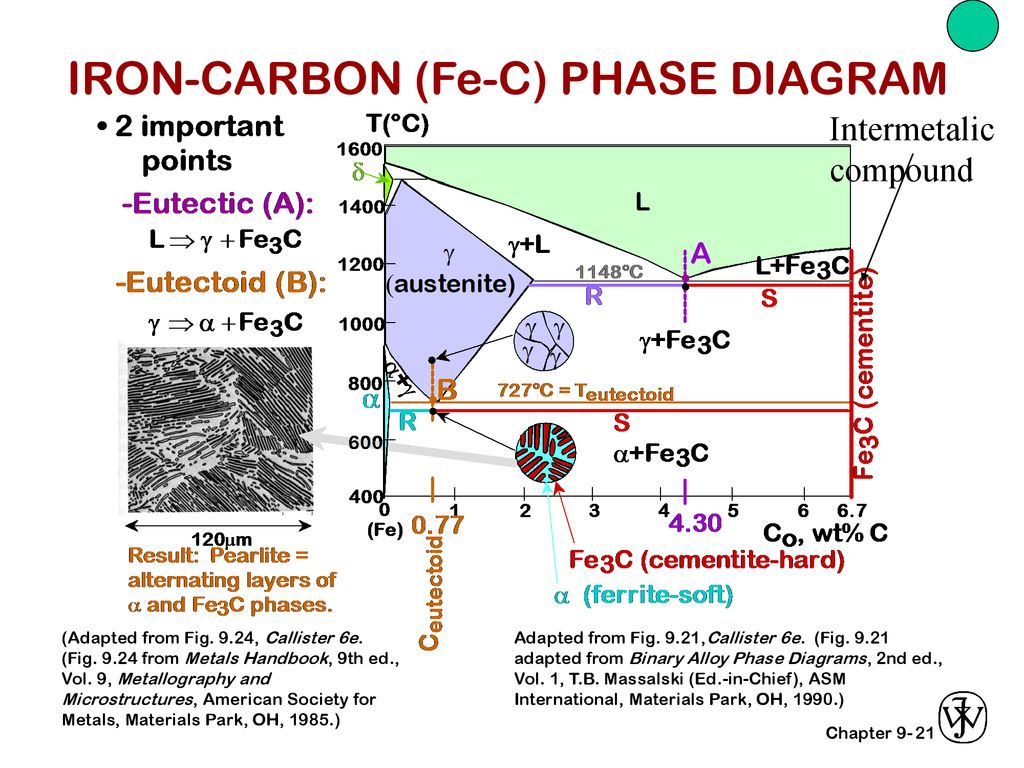
PDF The iron-iron carbide (Fe-Fe3C) phase diagram Review Fe-C phase diagram • 2 important points-Eutectoid (B): γ⇒α+Fe 3C-Eutectic (A): L ⇒γ+Fe 3C Fe 3 C (cementite) 1600 1400 1200 1000 800 600 400 0 12 3 4 5 66.7 L γ (austenite) γ+L γ+Fe 3C α+Fe 3C α + γ L+Fe 3C δ (Fe) C o, wt% C 1148°C T(°C) α 727°C = Teutectoid A R S 4.30 Result: Pearlite = alternating layers of αand Fe ...

Fe-Carbon Phase Diagram - ppt video online download
staff.emu.edu.tr › emirtascioglu › DocumentsFe-C Diagram - Eastern Mediterranean University (Fe) C, wt% C 1148ºC T(ºC) a 727ºC (Fe-C System) C 0 76 Hypoeutectoid Steel (EXAMPLE 2) Adapted from Figs. 9.24 and 9.29,Callister & Rethwisch 8e. (Fig. 9.24 adapted from Binary Alloy Phase Diagrams, 2nd ed., Vol. 1, T.B. Massalski (Ed.-in-Chief), ASM International, Materials Park, OH, 1990.) Adapted from Fig. 9.30, Callister & Rethwisch 8e.

The Iron Carbon Phase Diagram
Phase Diagram - Google Search 計算熱力学はいわば"物性推算法"の一つであり、用いる熱力学データベースも、もっとも良さそうな"推算値"で構成されています。. これらは様々な情報に基づき、細心の注意を払って推定されたものですが、間違いや問題はあり得ます。. 従って、それ ...

Heat Treater's Color Poster - ASM International
(PDF) Fe-C Phase Diagram | Bogdan Chiriac - Academia.edu Fe-C Phase Diagram Fe-C Phase Diagram Pure Iron 1538°C • Upon heating pure Iron experiences two Melts changes in crystal structure. or α iron.
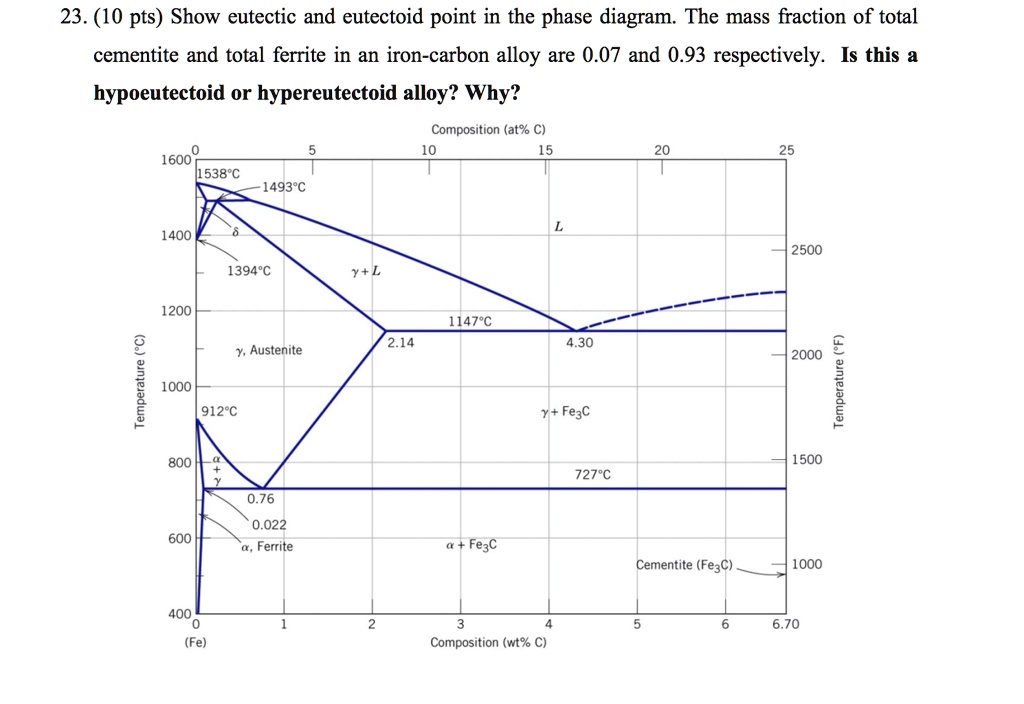
SOLVED:23. (10 pts) Show eutectic and eutectoid point in the ...
fe-c diagram - SlideShare fe-c diagram 1. The Iron-Carbon Phase Diagram 2. Iron-Carbon Phase Diagram • In their simplest form, steels are alloys of Iron (Fe) and Carbon (C). The Fe-C phase diagram is a fairly complex one, but we will only consider the steel and cast iron part of the diagram, up to 6.67% Carbon. 3. Fe - C Equilibrium Diagram 4.
What is the use of an iron carbide phase diagram? - Quora
fractory.com › iron-carbon-phase-diagramIron-Carbon Phase Diagram Explained [with Graphs] - Fractory The boundaries, intersecting each other, mark certain regions on the Fe3C diagram. Within each region, a different phase or two phases may exist together. At the boundary, the phase change occurs. These regions are the phase fields. They indicate the phases present for a certain composition and temperature of the alloy.
Practical Maintenance » Blog Archive » The Iron-Iron Carbide ...
Thermodynamics and phase diagram of the Fe-C system ... A critical review of published data provides a fairly accurate knowledge of the thermodynamic properties of all of the phases of the system Fe-C that are stable or metastable at atmospheric pressure. Selected data are shown as tables and equations. A proposed phase diagram differs only slightly from others recently published but has the following features. Peritectic compositions and the α-γ ...
![Iron-Carbon Diagram Explanation [PDF]](https://mechanicalenotes.com/wp-content/uploads/2018/10/Iron-Carbon-Phase-diagram-feature-image.png)
Iron-Carbon Diagram Explanation [PDF]
The Iron-Carbon Alloys And Fe-C Phase Diagram - MechanicalBase What Is Iron-Carbon Phase Diagram? Iron-Carbon (Fe-C) phase diagram. The iron-carbon phases and phase diagram is slightly complex, compared with other diagrams. The horizontal axis of the Fe-C diagram shows the percentage of carbon inside the Fe-C systems. The solubility limit of carbon inside the iron is very low.
The C-Fe (carbon-iron) system

lron–Iron-carbide System Fe and Fe3C (iron carbide) are the ...

IRON-CARBON PHASE DIAGRAM (PT1) How to build the phase diagram
Carbon Steels and the Iron-Carbon Phase Diagram – IspatGuru

The Iron Carbide (Fe Fe3C) Phase Diagram - UPRM - Flipbook by ...

GATE Metallurgical Engineering: Iron-Iron carbide Phase Diagram
Phase diagram of iron under extreme conditions measured with ...

Fe-C phase diagram (CALPHAD.com). | Download Scientific Diagram
Phase Diagram for Fe-C-X

Teach Yourself Phase Diagrams
Chapter 9: Phase Diagrams
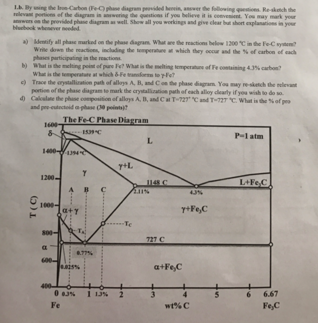
Answered: 1.b. By using the Iron-Carbon (Fe-C)… | bartleby
Solidification of steels

Briefly explain the eutectic and eutectoid reactions in Iron ...
Introduction - Microstructures - Cast Irons, High Alloy ...

Pin on smithing
Iron-Carbon Alloys | Article about Iron-Carbon Alloys by The ...

The Iron Carbon Phase Diagram
Lectures of Metallurgy Second Stage 1-9 Three-phase reactions ...

DOC-20160928-WA0008.pdf - The Iron–Iron Carbide (Fe–Fe3C ...
1. Introduction High carbon alloys from Fe-Cr system are well ...
Iron–Iron Carbide (Fe–Fe3C) Phase Diagram
PPT - The Iron–Iron Carbide (Fe–Fe 3 C) Phase Diagram ...
C-Cu-Fe (Carbon-Copper-Iron) | SpringerLink
0 Response to "41 fe-c phase diagram"
Post a Comment