38 transfer function from block diagram
PDF Chap. 7] Block Diagram Algebra and Transfer Functions of ... The block diagram for n transfer functions G1,.Ga ..... G, in cascade is given in Fig. 7-11. Xl Xÿ Xn Fig. 7-11 The output transform for any block is equal to the input transform multiplied by the transfer function (see Section 6.1). Therefore X2 = XaG1, X3 = X2G2 ..... Control Systems - Block Diagram Reduction Step 1 − Find the transfer function of block diagram by considering one input at a time and make the remaining inputs as zero. Step 2 − Repeat step 1 for remaining inputs. Step 3 − Get the overall transfer function by adding all those transfer functions. The block diagram reduction process takes more time for complicated systems.
control engineering - Transfer function into block diagram ... Transfer function into block diagram and matrix form. Ask Question Asked 1 year, 4 months ago. Active 1 year, 4 months ago. Viewed 132 times 0 $\begingroup$ I'm reading a book on Control System Design and running into the same issue I had in Kinematic Design. When things are presented in a format without any numerical examples it just appears ...
Transfer function from block diagram
PDF Transfer Functions Transfer Functions In this chapter we introduce the concept of a transfer function between an input and an output, and the related concept of block diagrams for feedback systems. 6.1 Frequency Domain Description of Systems The idea of studying systems in the frequency domain is to characterize a PDF Chap. 71 Block Diagram Algebra and Transfer Functions of ... 160 BLOCK DIAGRAM ALGEBRA AND TRANSFER FUNCTIONS OF SYSTEMS [CHAP. 7 Let the - 1 block be absorbed into the summing point: Step 4c Step 5: By Equation (7.3), the output C, due to input U is C, = [G2/(1 + G1G2)]U. The total output is C=C,+C,= [ ~ 1 +G2G2] [ A] [ A] IGIR + 7.8 REDUCTION OF COMPLICATED BLOCK DIAGRAMS The block diagram of a practical feedback control system is often quite complicated. PDF Block Diagrams Introduction 2. Simple Examples .. . mx bx s W As a block diagram we can represent the system by F (s) W(s) X (s) Fig. 1. Block diagram for a system with transfer function W(s). Sometimes we write the formula for the transfer function in the box representing the system. For the above example this would look like F (s) 1 ms2 + bs+ k X (s) Fig. 2. Block diagram giving the formula for the ...
Transfer function from block diagram. PDF C.02 Transfer Functions and Block Diagrams Chapter 2 Transfer Functions and Block Diagrams 4 2. Transfer Functions and Block Diagrams 2.1 Introduction - Review of Laplace transform - Using Laplace transform to solve a differential equation 2.2 Review of Laplace Transforms Definition: The Laplace transform off (t) , a sectionally continuous function of time, denoted by L[ f (t)], is ... Create Block Diagram From Transfer Function at Barbara ... 30 Transfer Function From Block Diagram Wiring Diagram. 4 answers active oldest votes 1 you have missed the feedback path. Where c (s) is the output and r (s) is the input of that particular block. Step 2 transform the block diagram to canonical form, using the transformations of section 7.5. Compare this equation with the standard form of the ... Find the final transfer function for the following block ... 4. (25 points) Find the final transfer function for the following block diagram. Show (and draw) the resulting block diagrams one step at a time for every applied rule (algebra for block diagrams). ... Transfer Functions in Block Diagrams - APMonitor Transfer Functions in Block Diagrams One source of transfer functions is from Balance Equations that relate inputs and outputs. Transfer functions are compact representations of dynamic systems and the differential equations become algebraic expressions that can be manipulated or combined with other expressions.
PDF Section 2 Block Diagrams & Signal Flow Graphs Block diagrams consist of Blocks-these represent subsystems - typically modeled by, and labeled with, a transfer function Signals- inputs and outputs of blocks -signal direction indicated by arrows -could be voltage, velocity, force, etc. Transfer Function and Block Diagram of Control System ... Nov 5, 2018 — The output is related to the input through a function called transfer function. This function is represented by a block and the complete diagram ...5 pages Control Systems - Block Diagrams - Tutorialspoint The transfer function of a component is represented by a block. Block has single input and single output. The following figure shows a block having input X (s), output Y (s) and the transfer function G (s). Transfer Function, G ( s) = Y ( s) X ( s) ⇒ Y ( s) = G ( s) X ( s) Section 5: Block Diagrams - Oregon State University Block diagrams consist of Blocks- these represent subsystems - typically modeled by, and labeled with, a transfer function Signals- inputs and outputs of blocks - signal direction indicated by arrows - could be voltage, velocity, force, etc.
Transfer Function From Block Diagram Representation MCQ ... Get Transfer Function From Block Diagram Representation Multiple Choice Questions (MCQ Quiz) with answers and detailed solutions. Download these Free Transfer Function From Block Diagram Representation MCQ Quiz Pdf and prepare for your upcoming exams Like Banking, SSC, Railway, UPSC, State PSC. What is the transfer function of this block diagram Transfer function block diagram. 1. Find the difference equation and draw the simulation diagram. 4. Find transfer function from root locus and step response diagram? 3. Poles and zeros of a transfer function. 0. Block diagram for a complex impulse response. 0. Inverse Fourier of Two-Pole Transfer Function. Transfer Functions - Michigan Technological University Block Diagram Equivalence: Series: is equivalent to Parallel: is equivalent to: Positive Feedback: is equivalent to: Negative Feedback: is equivalent to. Additional Rules: Summing Junctions For the transfer functions of multiple inputs: u 1, u 2, etc., to output y, use superposition. That is, for the transfer function of u 1 to y, disregard the ... Block Diagram of Control Systems (Transfer Functions ... Block Diagram of Closed Loop Control System. In a closed-loop control system, a fraction of output is fed-back and added to the system's input. If H (s) is the transfer function of the feedback path, then the transfer function of the feedback signal will be B (s) = C (s)H (s). At the summing point, the input signal R (s) will be added to B (s ...
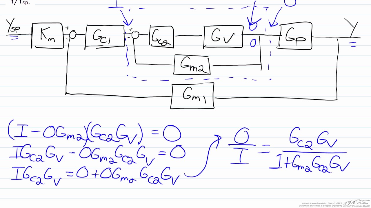
Transfer Functions for Cascade Control Using a Block Diagram
TRANSFER FUNCTIONS AND BLOCK DIAGRAMS - Academia.edu Write down the transfer function Y (s)/R (s) of the following block diagram. R (s) Y (s) K G (s) + _ a) For G (s) = 1/ (s + 10) and K = 10, determine the closed loop transfer function with MATLAB. b) For K = 1, 5, 10, and 100, plot y (t) on the same window for a unit-step input r (t) with MATLAB, respectively. Comment on the results.
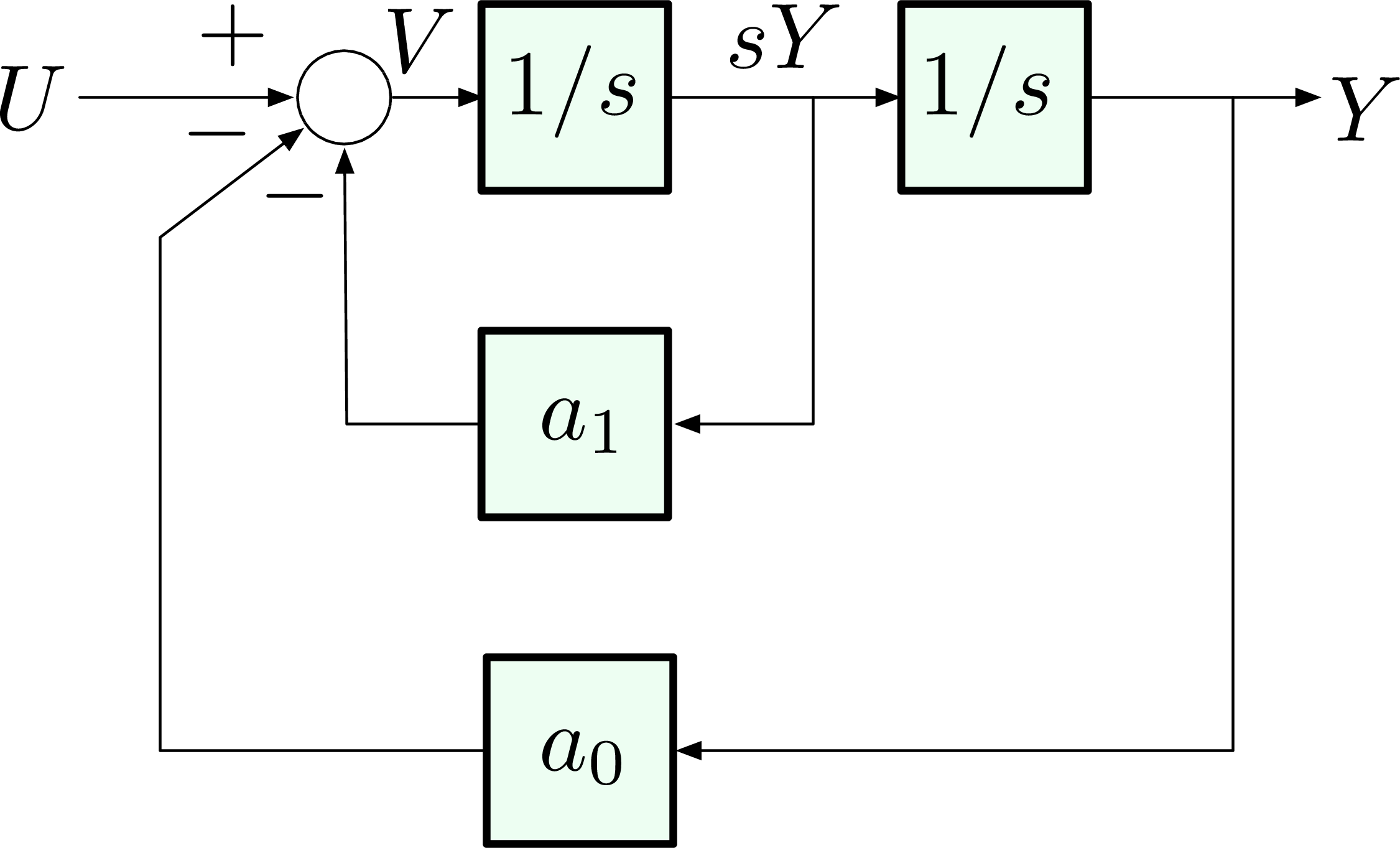
ECE 486 Control Systems
discrete signals - Transfer function block diagram ... Block diagram transfer function of a line. 1. DTFT and Inverse DTFT Homework Problem. 1. Drawing the modulus from a Transfer function. 1. How can I correctly plot an impulse_response() of a discrete transfer function? 1. Real Data Complex Transfer Function using H0, H1, H2 Estimators. 0.
Solved Reduce block diagram to transfer function | Chegg.com
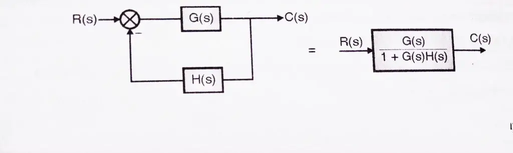
PDF Worked examples block diagrams transfer functions Worked Examples on block diagrams/transfer functions 31st January 2012 1. For the closed-loop feedback control system with input R and output X shown in the figure above, derive the open-loop transfer function and the closed-loop transfer function. Answer: For the inner negative unity-feedback closed loop system, using GH G Gc s 1 ( ) we have ...
homework - How can I find the transfer function of the ...
PDF Lecture 4: Transfer Function and Block Diagram (Continued) 2. Block diagram models The block diagram is a diagrammatic means to represent the cause-and-effect relationship of system variables. It consists of unidirectional, operational blocks that represent the transfer function of the variables of interests. Fig.4: Components of a block diagram for a linear, time-invariant system
Closed-Loop Transfer Function Block Diagram - CircuitLab
Transfer function of Block Diagrams | Exercise 1 The tricky thing to calculate the transfer function for these block diagrams is actually the algebra, you have to be careful with some sign or with some number that we do not place or forget out there on the way, but in itself it's simple, quiet. If you want to know more about these topics you can read the following book: Ogata, K. (2003).

To perform a block diagram reduction using MATLAB | Matlab ...
Transfer Function of Control System - Electrical4U A transfer function represents the relationship between the output signal of a control system and the input signal, for all possible input values. A block diagram is a visualization of the control system which uses blocks to represent the transfer function, and arrows which represent the various input and output signals.
Transfer Function of Block Diagram | Physics Forums
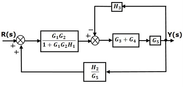
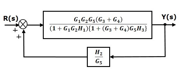
1 3.19 Find the transfer functions for the block diagrams in Fig ... 3.22 Use block-diagram algebra to determine the transfer function between R(s) and Y(s) in Fig. 3.57. Solution: Move node A and close the loop:.7 pages

Chapter 4 Block Diagrams and SFGs - Block diagram ...
PDF fab16002multi-20151004171453 Transfer Functions, Block Diagrams, and Signal Flow Graphs Problems 2.1 Compute the transfer function of the depicted block diagram a. By reduction H2(s) G3(s) Hi(s) H3(s) Solution 45 Gds) a. By applying transformation 7 (Table F2.1), the branch point at the left of the block with transfer function G4(s) is moved at the right of G4(s).
 eNotes: Mechatronics and Controls" width="832" height="235" style="width:100%;" onerror="this.parentNode.parentNode.remove();">
H1 align="center">eNotes: Mechatronics and Controls
Simulink Transfer function/ block diagram - MathWorks This block diagram can certainly be recreated in Simulink. I suggest you start with 'Transfer Function' blocks and 'Sum' blocks, to match the transfer functions and sums in the diagram. I am not sure what the 'F' blocks in your diagram refer to, but if they are simply gains, then you can use a 'Gain' block to represent each one.
Section 1: Introduction
Laplace transform, transfer function and block diagram ... Laplace transform, transfer function and block diagram analysis of LTI dynamic systems. Exercise 1.1 - Solution of differential equations.22 pages

Block diagram of PCC voltage controller The open loop ...
Block Diagram Simplifier - schematron.org all steps for block diagram reduction for a complex block diagram. Eliminate loop I & simplify as GGG + B 1G 2H) (sY 4G 2G 1H AB 3G. Visual algebra: use block diagram manipulation instead of algebra. • Block: transfer function of a subsystem. • Line: Laplace transform of a variable.
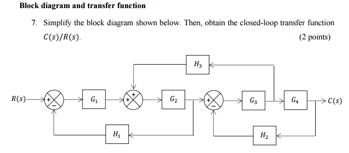
Solved Block diagram and transfer function Simplify the ...
Block diagram reduction Techniques - Transfer Function o Transfer functions of elements inside the blocks o Summing points o Take off points o Arrow Block diagram A control system may consist of a number of components. A block diagram of a system is a pictorial representation of the functions performed by each component and of the flow of signals.
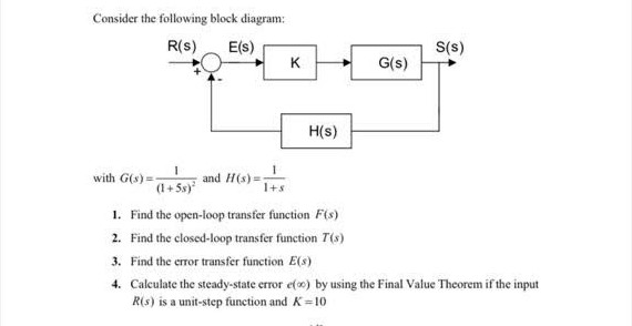
Solved Consider the following block diagram: R(S) E(s) S(s ...
Transfer function example block diagram Find the transfer function for a single Block Diagrams • A transfer function converts an inputto an output From the definition of a block, Example #2 U (s) + G 3 (s) Z (s) U (s) Z (s) find + G 1 (s) G Chapter 2 Transfer Functions and Block Diagrams 4 2.
Block diagram transfer function of a line - Signal Processing ...
Transfer function block diagram - - StuDocu Transfer function: It is defined as the ratio of the Laplace transform of the output variable to the Laplace transform of the input variable, with all zero initial conditions. Block diagram: It is used to represent all types of systems.
Control Systems - Block Diagram Reduction
Solved Reduce the block diagram shown below to a single ... Electrical Engineering questions and answers. Reduce the block diagram shown below to a single transfer function, T (s) = C (s)/R (s). Use the following methods: R (S) + 1 50 C (S) +-- E000 S S+1 2 S 2 (a) Block diagram reduction (Section: 5:2] (b) MATLAB. Question: Reduce the block diagram shown below to a single transfer function, T (s) = C ...
Block Diagram Reduction Shortcut Rules In Control System !!
PDF Block Diagrams Introduction 2. Simple Examples .. . mx bx s W As a block diagram we can represent the system by F (s) W(s) X (s) Fig. 1. Block diagram for a system with transfer function W(s). Sometimes we write the formula for the transfer function in the box representing the system. For the above example this would look like F (s) 1 ms2 + bs+ k X (s) Fig. 2. Block diagram giving the formula for the ...

Simplify the block diagram shown in the figure. Obtain the ...
PDF Chap. 71 Block Diagram Algebra and Transfer Functions of ... 160 BLOCK DIAGRAM ALGEBRA AND TRANSFER FUNCTIONS OF SYSTEMS [CHAP. 7 Let the - 1 block be absorbed into the summing point: Step 4c Step 5: By Equation (7.3), the output C, due to input U is C, = [G2/(1 + G1G2)]U. The total output is C=C,+C,= [ ~ 1 +G2G2] [ A] [ A] IGIR + 7.8 REDUCTION OF COMPLICATED BLOCK DIAGRAMS The block diagram of a practical feedback control system is often quite complicated.

Solved For the following block diagram: Find the transfer ...
PDF Transfer Functions Transfer Functions In this chapter we introduce the concept of a transfer function between an input and an output, and the related concept of block diagrams for feedback systems. 6.1 Frequency Domain Description of Systems The idea of studying systems in the frequency domain is to characterize a

Transfer function block diagram representation of an isolated ...

Transfer function algebra – x-engineer.org

Block Diagram of Control Systems (Transfer Functions ...
Control Systems - Block Diagram Reduction
1 3.19 Find the transfer functions for the block diagrams in ...

Closed-loop transfer function - Wikipedia

Transfer function algebra – x-engineer.org
control systems - how to obtain the transfer function from ...

Converting a transfer function to state space | Quadratics ...

Transfer function block diagram of the system. | Download ...
Control System - Solved Example of Block Reduction Technique ...
Problem 1 on Block Diagram Reduction

Answered: Find the transfer function of the… | bartleby

Block diagrams and their transfer functions for the exact ...
Section 1: Introduction

Reduce the block diagram shown to a single transfer function ...

Engineer On A Disk

Block Diagram of Control Systems (Transfer Functions ...

Transfer Function from a Simple Block Diagram Find the ...
Control Systems - Block Diagram Reduction
0 Response to "38 transfer function from block diagram"
Post a Comment