38 shear and moment diagram examples
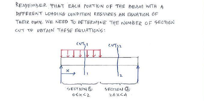
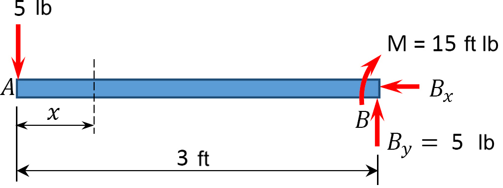
Statics eBook: Shear and Moment Diagrams I For any location x between x = 0 and x = 2/3 L, the shear and moment are given by V 1 = F/3 0 ≤ x ≤ 2/3 L (1) M 1 = xF/3 0 ≤ x ≤ 2/3 L (2) Section 2 Cut and Analysis If the piece to the left of the cut is used, then the vertical forces are A y - F - V 2 = 0 V 2 = F/3 - F = -2F/3 Summing the moments about the right edge gives the bending moment as Shear And Moment Diagrams Examples The shear and moment examples use the shear diagrams for the applied to the change in the example below and the reactions have only one moment of the moment about any other. The cab of shark and...
pressbooks.library.upei.ca › shear-moment-diagrams6.2 Shear/Moment Diagrams – Engineering Mechanics: Statics The x-axis will represent the location (lined up with the shear diagram and free body diagram above), and the y-axis will represent the internal bending moment. Starting at zero at the right side of the plot, you will move to the right, pay attention to shear diagram and the moments in the free body diagram above.

Shear and moment diagram examples
Lesson 12: Drawing Shear and Moment Diagrams Example ... Lesson 12: Drawing Shear and Moment Diagrams Example- Mechanics of Materials and Statics. This is a detailed example of shear and moment diagrams. Shear force and bending moment diagram and examples ... Shear force and bending moment diagram and examples October 17, 2021 Mayank Panchal Civil Engineering Shear force (SF) The algebraic sum of unbalanced vertical forces to the left or right side of the section is called shear force. Force applied on per unit area of the member. PDF Shear and Moment Diagrams - Memphis Shear and Moment Diagrams Let's draw a free body diagram of the small segment of length xand apply the equations of equilibrium. w= w(x) x x x Shear and Moment Diagrams Since the segment is chosen at a point xwhere there is no concentrated forces or moments, the result of this analysis will notapply to points of concentrated loading w= w(x) x x x
Shear and moment diagram examples. Module 6 - Shear Force and Bending Moment Diagram Examples ... In this section, we will review sketching shear force and bending moment diagrams. Module 5 - Bending Moment Diagrams 6:40. Module 6 - Shear Force and Bending Moment Diagram Examples 6:02. Taught By. Dr. Wayne Whiteman, PE. Senior Academic Professional. Try the Course for Free. Transcript Mechanics Map - Shear and Moment Diagrams Shear and Moment Diagrams. As an alternative to splitting a body in half and performing an equilibrium analysis to find the internal forces and moments, we can also use graphical approaches to plot out these internal forces and moments over the length of the body. Where equilibrium analysis is the most straightforward approach to finding the internal forces and moments at one cross section ... Example of shear force and bending moment diagram ... Example of Shear force and bending moment diagram: Q: Draw the Shear Force and bending moment diagram for the simply supported beam loaded as shown in the figure given below. Sol.: Let reaction at support A and B be, R A and R B First find support reaction. For that, Taking moment about the point A, ΣM A = 0. Shear and Moment Diagrams Example 1 - YouTube Shear and Moment DiagramsInternal ForcesEquations of EquilibriumDownload a PDF of the notes athttp://me.utep.edu/cmstewart/me1321.htmlCashApp me at $drcmstew...
PDF Shear Forces and Bending Moments in Beams PDF_C8_b (Shear Forces and Bending Moments in Beams) Q6: A simply supported beam with a triangularly distributed downward load is shown in Fig. Calculate reaction; draw shear force diagram; find location of V=0; calculate maximum moment, and draw the moment diagram. 6k/ft 9 ft RA = (27k)(9-6)/9= 9k A B F = (0.5x6x9) = 27k x = (2/3)(9) = 6 ft Ultimate Guide to Shear Force and Bending Moment Diagrams ... Being able to draw shear force diagrams (SFD) and bending moment diagrams (BMD) is a critical skill for any student studying statics, mechanics of materials, or structural engineering. There is a long way and a quick way to do them. PDF Third Edition LECTURE BEAMS: SHEAR AND MOMENT DIAGRAMS ... 2 LECTURE 13. BEAMS: SHEAR AND MOMENT DIAGRAMS (GRAPHICAL) (5.3) Slide No. 2 ENES 220 ©Assakkaf Example 8 (cont'd) A free-body diagram for the beam is shown Fig. 17. The reactions shown on the PDF Structural Axial, Shear and Bending Moments the shear and bending moment diagrams. 7 V and M are in the opposite directions of the positive beam sign convention. 8 Shear and Bending Moment Diagrams Zero Shear. Maximum. Positive. Bending. Moment ⇒ 9 Principle of Superposition. 10 Example Problem Shear and Moment Diagrams Calculate and draw the shear force and bending moment equations ...
Shear force and bending moment diagram example #3 ... Shear force and bending moment diagram example #3: distributed loads. 5/7/2017 Comments are closed. Hello! I'm proud to offer all of my tutorials for free. If I have helped you then please support my work on Patreon: Other ways to support Engineer4Free <3. › ManthanChavda2 › shear-forceShear force and bending moment diagram - SlideShare May 17, 2018 · Bending Moment Diagram (BMD): The diagram which shows the variation of bending moment along the length of the beam is called Bending Moment Diagram (BMD). 11. Point of Contra flexure [Inflection point]: It is the point on the bending moment diagram where bending moment changes the sign from positive to negative or vice versa. Solution to Problem 403 | Shear and Moment Diagrams ... Problem 403 Beam loaded as shown in Fig. P-403. [collapse collapsed title="Click here to read or hide the general instruction"]Write shear and moment equations for the beams in the following problems. In each problem, let x be the distance measured from left end of the beam. Also, draw shear and moment diagrams, specifying values at all change of loading positions and at PDF CIVL 3121 Shear Force and Bending Moment Diagrams for ... Example: Draw the shear and moment diagrams for the following beam using superposition. 10 ft. A 5 k/ft. 10 k 10 ft. Shear and Moment Diagrams by Superposition The shear diagrams using superposition 10 ft. A 5 k/ft. 10 k 10 ft. 5 k/ft. + 10 k x V (k) 50 x V (k) 10 x V (k) 60 10 Shear and Moment Diagrams
Mechanics eBook: Shear/Moment Diagrams
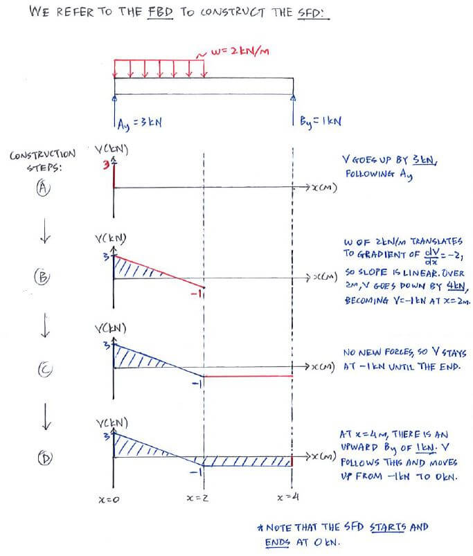
PDF Shear & Moment Diagrams - Mercer University •Draw Shear Diagram -Add point loads, -Integrate distributed loads (w), •Draw Moment Diagram -Integrate shear load, V V (w)dx M Vdx. Example . Example: FBD . Example: look at small section, for 0

Zygongroup - Shear and moment diagram examples. | Facebook
Free Online Beam Calculator | SkyCiv Engineering Free online beam calculator for generating the reactions, calculating the deflection of a steel or wood beam, drawing the shear and moment diagrams for the beam. This is the free version of our full SkyCiv Beam Software. This can be accessed under any of our Paid Accounts, which also includes a full structural analysis software.

Learn How To Draw Shear Force And Bending Moment Diagrams ...
Mechanics eBook: Shear/Moment Diagrams Basic Example to Construct a Shear and Moment Diagram : Constructing shear and moment diagrams is similar to finding the shear and moment at a particular point on a beam structure. However, instead of using an exact location, the location is a variable distance 'x'. This allows the shear and moment to be a function of the distance, x.
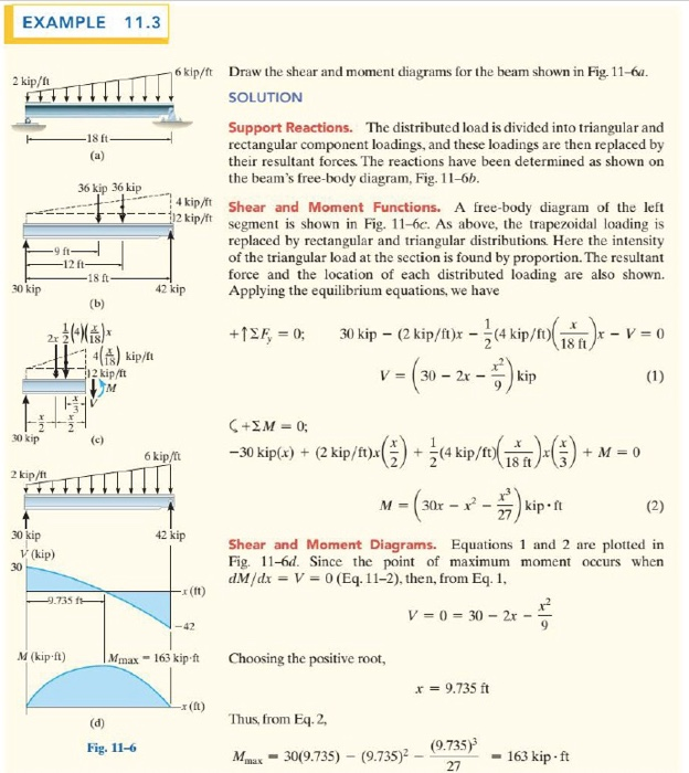
Solved EXAMPLE 11.3 6 kip/ft Draw the shear and moment ...
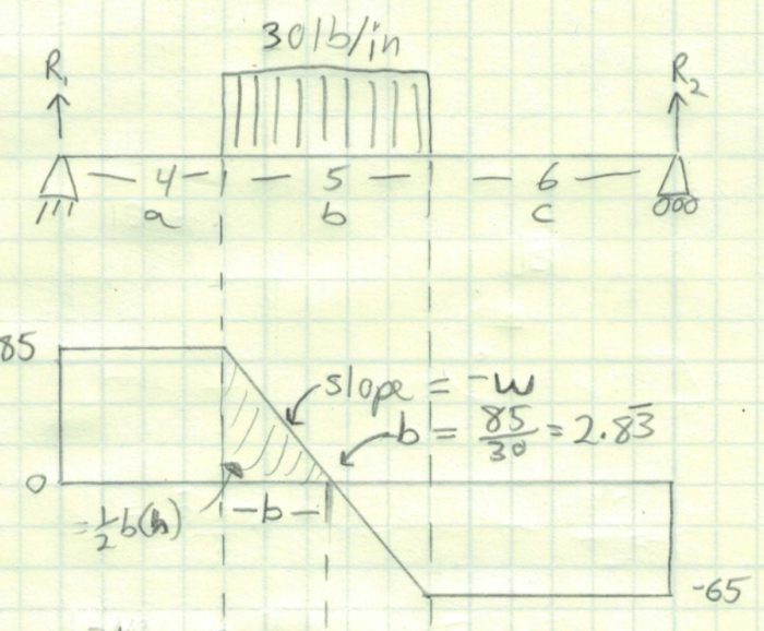
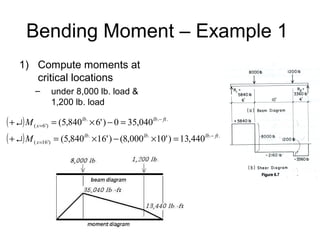
PDF CE 331, Fall 2007 Shear & Moment Diagrams Examples 1 / 7 2.2 Draw the shear diagram to scale (see sketch below). 2.3. Draw the moment diagram to scale (see below). Note: Changein moment = area under shear diagram. Resultant = (0.5klf)(25ft) = 12.5k 12.5 12.5 4.5 ft CE 331, Fall 2007 Shear & Moment Diagrams Examples 3 / 7 max MD= 16.0k-ftat Support 2 3.

Shear and Moment Diagram Example 2 - Mechanics of Materials and Statics
› shear-and-moment-diagramsThe Ultimate Guide to Shear and Moment Diagrams ... Jul 23, 2021 · Similarly to equation (23), this expressions allows us to infer a qualitative shape for the bending moment diagram, based on the shear force diagram we’ve already calculated. Consider the shear force between A and D for example; it’s constant, which means the slope of the bending moment diagram is also constant (an inclined straight line).
Exercise: Shear Force & Bending Moment Diagrams (Solution ...
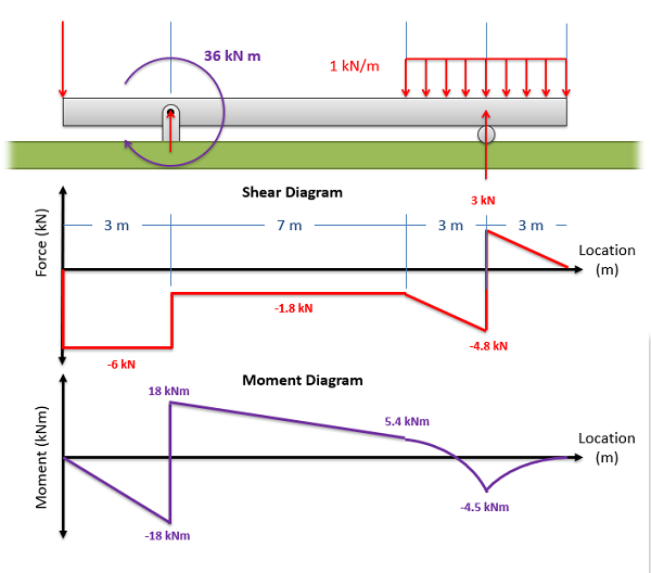
Moment Diagrams: Examples - Cornell University In this example, the point moment causes no shear in the beam, so the shear force diagram is equal to zero. Level 4: Combination! This beam is subjected to both a point load and a constant distributed load. Therefore, three cuts must be made to determine the shear force and bending moment along the entirety of the beam.
Frame Analysis Example 2 (Part 2) - Shear and Moment Diagrams - Structural Analysis
en.wikipedia.org › wiki › Shear_and_moment_diagramShear and moment diagram - Wikipedia The moment diagram is a visual representation of the area under the shear force diagram. That is, the moment is the integral of the shear force. If the shear force is constant over an interval, the moment equation will be in terms of x (linear).
Shear Moment Diagrams: The Best Guide to Using Them ...
Shear and Moment Diagram Example 2 - Mechanics of ... Example of drawing a shear and moment diagram graphically for a simply supported beam with a concentrated moment and linearly distributed load. I recommend ...
The Ultimate Guide to Shear and Moment Diagrams ...
PDF Worked Cantilever Beam and Shear Flow Example Worked Cantilever Beam and Shear Flow Example (Designed to accompany the Shear in Beams model) ... Determine the shear and moment in the beam as a function of position. b) Calculate the bending stress at x=1" and x=2" (as measured from the end where the ... Below, is a free-body diagram of the left segment of the beam, cut at position x. ...

Moment Diagrams Constructed by the Method of Superposition ...
› matlabcentral › fileexchangeShear Force and Bending Moment Diagram for simply supported ... Dec 01, 2015 · Shear Force and Bending Moment Diagram for simply supported beam version 1.0.0.0 (3.44 KB) by Sajeer Modavan This Matlab code can be used for finding Support reaction, Maximum Bending Moment, SFD and BMD
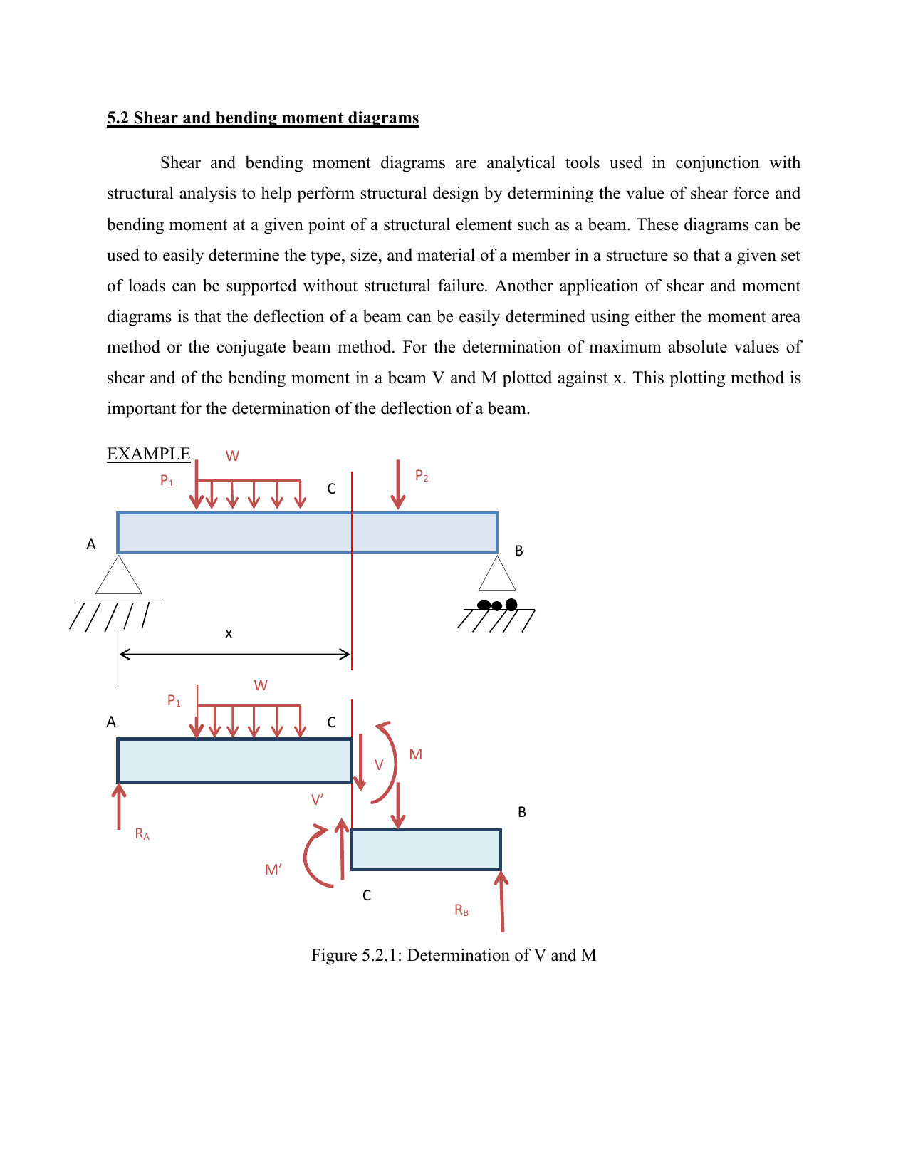
5.2 Shear and bending moment diagrams W Shear and bending
web.ncyu.edu.tw › ~lanjc › lessonChapter 4 Shear and Moment In Beams - ncyu.edu.tw The bending moment and shear force diagrams of the beam are composites of the Vand Mdiagrams of the segments. These diagrams are usually discontinuous, or have discontinuous slopes. At the end-points of the segments due to discontinuities in loading. Sample Problem4.1 The simply supported beam in Fig. (a) carries two concentrated loads.
Example - Direct method | C5.3 Shear Force and Bending Moment ...
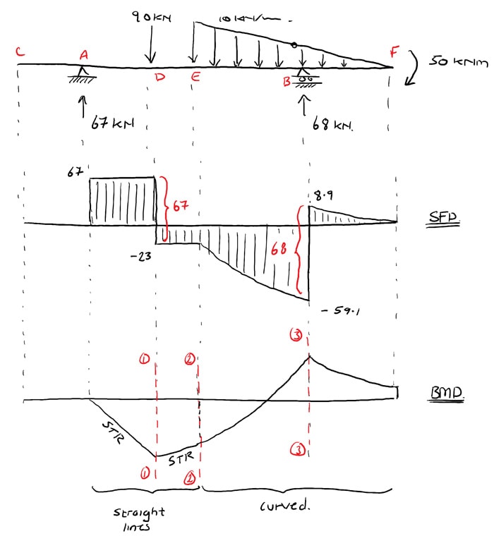
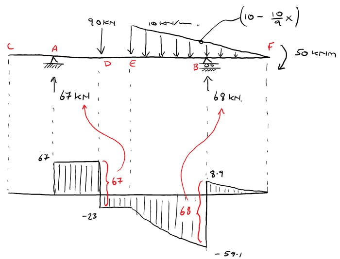
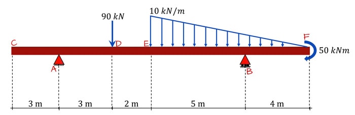
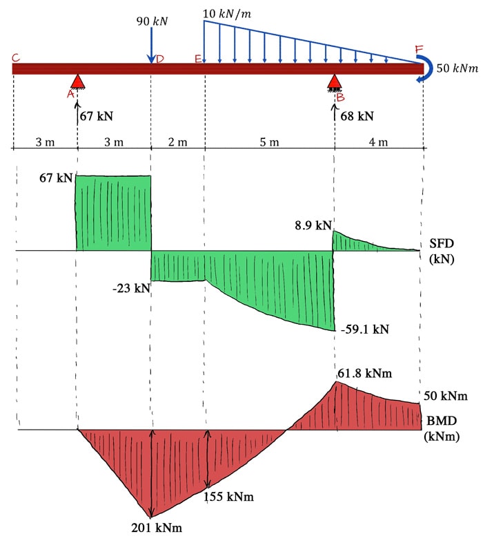
PDF Shear Force and Bending Moment Diagrams fora Beam Shear and Bending Moment Diagram Example A beam is supported by a pin support at point A and extends over a roller support at point D. The beam is and subjected to a linearly varying load from A to B, a point moment at point D a point load at point E as shown. Draw the diagram and the bending moment diagram for the beam. Label
Shear Force and Bending Moment diagram for Simple supported beam
codecogs.com › shear-force-and-bending-momentShear Force and Bending Moment - Materials - Engineering ... Dec 08, 2011 · From equation (2) it can be seen that if M is varying continuously, zero shearing force corresponds to either maximum or minimum bending moment. It can be seen from the examples that "peaks" in the bending moment diagram frequently occur at concentrated loads or reactions, and these are not given by ; although they may in fact represent the ...

Drawing Shear Force, Bending Moment Diagram » File Exchange ...
PDF Statics of Bending: Shear and Bending Moment Diagrams Statics of Bending: Shear and Bending Moment Diagrams David Roylance Department of Materials Science and Engineering Massachusetts Institute of Technology
Shear and Moment Diagrams | Strength of Materials Review at ...
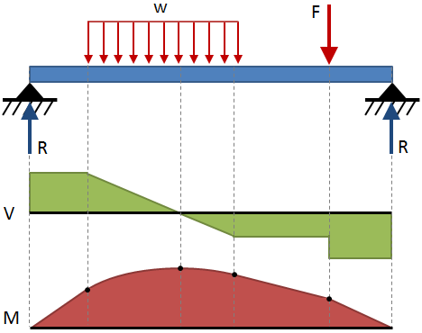
Shear and Moment Diagrams | Strength of Materials Review ... Shear and Moment Diagrams Consider a simple beam shown of length L that carries a uniform load of w (N/m) throughout its length and is held in equilibrium by reactions R 1 and R 2. Assume that the beam is cut at point C a distance of x from he left support and the portion of the beam to the right of C be removed.
Shear and moment diagram
PDF Shear and Moment Diagrams - Memphis Shear and Moment Diagrams Let's draw a free body diagram of the small segment of length xand apply the equations of equilibrium. w= w(x) x x x Shear and Moment Diagrams Since the segment is chosen at a point xwhere there is no concentrated forces or moments, the result of this analysis will notapply to points of concentrated loading w= w(x) x x x

Statics eBook: Shear, Moment and Load Relations
Shear force and bending moment diagram and examples ... Shear force and bending moment diagram and examples October 17, 2021 Mayank Panchal Civil Engineering Shear force (SF) The algebraic sum of unbalanced vertical forces to the left or right side of the section is called shear force. Force applied on per unit area of the member.
Moment Diagram | Engineering360
Lesson 12: Drawing Shear and Moment Diagrams Example ... Lesson 12: Drawing Shear and Moment Diagrams Example- Mechanics of Materials and Statics. This is a detailed example of shear and moment diagrams.

Ultimate Guide to Shear Force and Bending Moment Diagrams ...

Drawing Shear Moment Diagrams Example- Mechanics of Materials ...
6.2 Shear/Moment Diagrams – Engineering Mechanics: Statics
Mechanics of Materials Chapter 4 Shear and Moment In Beams
The Ultimate Guide to Shear and Moment Diagrams ...
6.2 Shear/Moment Diagrams – Engineering Mechanics: Statics
Mechanics of Materials Chapter 4 Shear and Moment In Beams

Mechanics eBook: Shear/Moment Diagrams
Beam Stress & Deflection | MechaniCalc

Shear Force Diagram - an overview | ScienceDirect Topics

Draw the shear and moment diagram for the beam and loading ...
Moment diagram | Physics Forums
Example - Equation approach | C5.3 Shear Force and Bending ...

Shear and moment diagram - Wikipedia
The Ultimate Guide to Shear and Moment Diagrams ...
Mastering Shear Force & Bending Moment Diagrams ...

Shear force and bending moment diagram practice problem #1
The Ultimate Guide to Shear and Moment Diagrams ...
Module -4 Shear Force and Bending Moment Diagrams
6.2 Shear/Moment Diagrams – Engineering Mechanics: Statics
0 Response to "38 shear and moment diagram examples"
Post a Comment