42 consider the circuit diagram depicted in the figure
Solved (10%) Problem 10: Consider the circuit diagram - Chegg Transcribed image text: (10%) Problem 10: Consider the circuit diagram depicted in the figure. E1 = 18 V 250 R 0.522 E2-45V 50% Part (a) What equation do ... Solved (17%) Problem 5: Consider the circuit diagram - Chegg Transcribed image text: (17%) Problem 5: Consider the circuit diagram depicted in the figure E1 18 V 0.5 Ω 2.5 Ω 1.5Ω 0.52 45 V 50% Part (a) What equation ...
MasteringPhysics: Problem Print View - hi Consider this diagram. Let us assume that it describes a series circuit containing a resistor, a capacitor, and an inductor. The current in the circuit has amplitude , as indicated in the figure. Which of the following choices gives the correct respective labels of the voltages across the resistor, the capacitor, and the inductor?

Consider the circuit diagram depicted in the figure
Answered: Consider the network depicted in the… | bartleby Consider the network depicted in the following figure, and determine the equivalent impedance seen looking into the open terminals if w = 15 rad/s 2 mF 20 N : 25 Ω 55 Ω 2H Oa. 12.482 + J 3.864 0 Ob. 8.482 + J 7.864 2 Oc. 14.482 + J 1.864 2 Od. 10.482 + J 5.864 2 ell. check_circle. Answered: 34. 35. Calculate the secondary voltage… | bartleby Q: ENL Consider the circuit diagram depicted in the figure. E- 18 V 0.50 250 ww 1.50 0.50 (a) What equa... E- 18 V 0.50 250 ww 1.50 0.50 (a) What equa... A: Click to see the answer Again, consider the cooling of the square plastic sheet of ... This is depicted in Figure(a). The plastic surface is at T_{s}. The sheet dimension is again L × L. Assume that the sheet can be treated as a vertical, semi-infinite plate (i.e., neglecting the end effect due to finite length) and treat the thermobuoyant flow and heat transfer accordingly. (a) Draw the thermal circuit diagram.
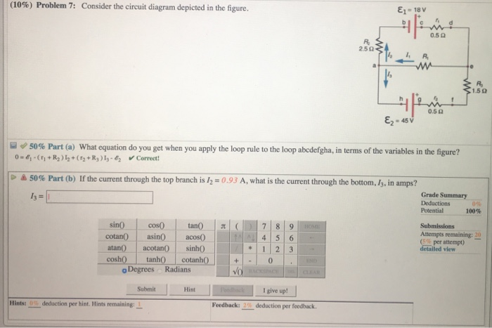
Consider the circuit diagram depicted in the figure. Consider The Circuit Diagram In The Figure - General ... Consider the circuit diagram depicted in the figure. Consider a series rc circuit as in the figure below for which r 100 mω c 500 µf and ε 300 v. B a 45 mh inductor is connected as shown in figure 12101b to an ac generator with. Assume that v 128 v r1 r2 r3 r4 r5 200 ω. Open Circuit Test Wikipedia. Consider the circuit diagram depicted in t... | Clutch Prep Problem Details. Consider the circuit diagram depicted in the figure. Part (a) What equation do you get when you apply the loop rule to the loop abcdefgha? Part (b) If the current through the top branch is I2 = 0.49 A, what is the current through the bottom I3, in amps? Learn this topic by watching Kirchhoff's Loop Rule Concept Videos. % Problem 30: Consider the circuit diagram in the figure ... View (3) Problem 30 Consider the circuit diagram in the figure. E1 = 18V.docx from AA 1 (3%) Problem 30: Consider the circuit diagram in the figure. E1 = 18V R Ez = 45 Otheexpertta.c 50% Part (a) Solved (4%) Problem 12: Consider the circuit diagram - Chegg Question: (4%) Problem 12: Consider the circuit diagram depicted in the figure. Ej-18V 0.5 ? 2.5 ? 12 R 1.5 ? 0.5 ? 50% Part a What equation do you get when ...
Solved Consider the circuit diagram depicted in the figure ... Physics. Physics questions and answers. Consider the circuit diagram depicted in the figure. What equation do you get when you apply the loop rule to the loop abcdefgha? If the current through the top branch is I_2 = 0.49 A. what is the current through the bottom, I_3, in amps? Question: Consider the circuit diagram depicted in the figure. Answered: Consider the circuit diagram depicted… | bartleby Consider the circuit diagram depicted in the fgure. It is known that two battery internal resistors r1and r2 are both 0.2Ω· = 12V and & = 24V. R2 16Ω 2. and Rs 262, but Ri is unknown. Caution: Current directions. A) Consider the combination of capacitors ... | Clutch Prep A) Consider the combination of capacitors shown in the diagram, where C 1 = 3.00 μF, C 2 = 11.0 μF, C 3 = 3.00 μF, and C 4 = 5.00 μF.. Find the equivalent capacitance C A of the network of capacitors. Express your answer in microfarads. B) Two capacitors of capacitance C 5 = 6.00 μF and C 6 = 3.00 μF are added to the network, as shown in the diagram. Find the equivalent capacitance C B ... Solved (11%) Problem 4: Consider the circuit diagram ... Transcribed image text: (11%) Problem 4: Consider the circuit diagram depicted in the figure. d 0.5 Q R. < R 1.5 22 0.522 Ez = 45 V > * 50% Part (a) What ...
(10) Problem 1 Consider the circuit diagram depicted in ... (10%) Problem 1: Consider the circuit diagram depicted in the figure. <1.592 0.50 45 V A 50% Part (a) What equation do you get when you apply the loop rule to the loop abcdefgha, in terms of the variables in the figure? > A 50% Part (b) If the current through the top branch is 12 = 0.83 A, what is the current Wk10a.pdf - The Expert TA | Human-like ... - Course Hero Note that all variables may not be required. α, β, θ, a, d, g, h, I 1, I 2, j, k, m Problem 2: Consider the circuit diagram depicted in the figure. Part (a) What equation do you get when you apply the loop rule to the loop abcdefgha, in terms of the variables in the figure? Solved (4%) Problem 10: Consider the circuit diagram - Chegg Transcribed image text: (4%) Problem 10: Consider the circuit diagram depicted in the figure E,-18 V 0.5 ? 2.5 ? /21R 1.59 0.52 50% Part (a) what equation ... Consider the circuit shown in the figure - Toppr Ask Consider the circuit shown in the figure. A. ... Diagram set > Problem solving tips > Mindmap > Common misconceptions > Cheatsheets > Memorization tricks > Practice more questions . JEE Mains Questions. 10 Qs > JEE Advanced Questions. 1 Qs > AIIMS Questions.
Ideal Current Source - an overview | ScienceDirect Topics
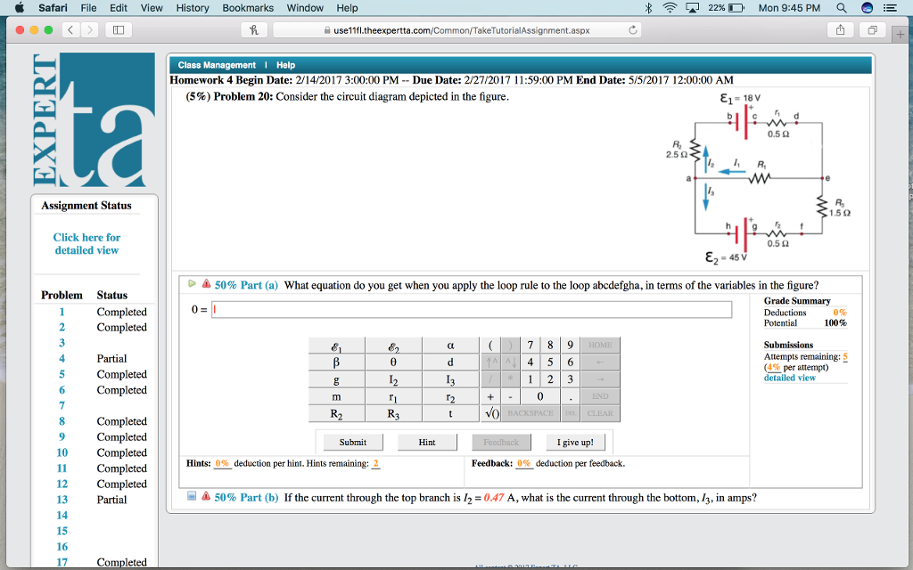
Solved Consider the circuit diagram depicted in the figure ... Transcribed image text: Consider the circuit diagram depicted in the figure. What equation do you get when you apply the loop rule to the loop abcdefgha, in terms of the variables in the figure? If the current through the top branch is I_2 = 0.47 A, what is the current through the bottom.

10) Problem 1 Consider the circuit diagram depicted in the ...
Solved (10%) Problem 5: Consider the circuit diagram ... Transcribed image text: (10%) Problem 5: Consider the circuit diagram depicted in the figure 0.5 Ω R2 2.5 Ω /2 R 1.5Ω 0.5 Ω 50% Part (a) what equation do ...

Topolectrical Weyl circuit. a circuit diagram of the Weyl ...
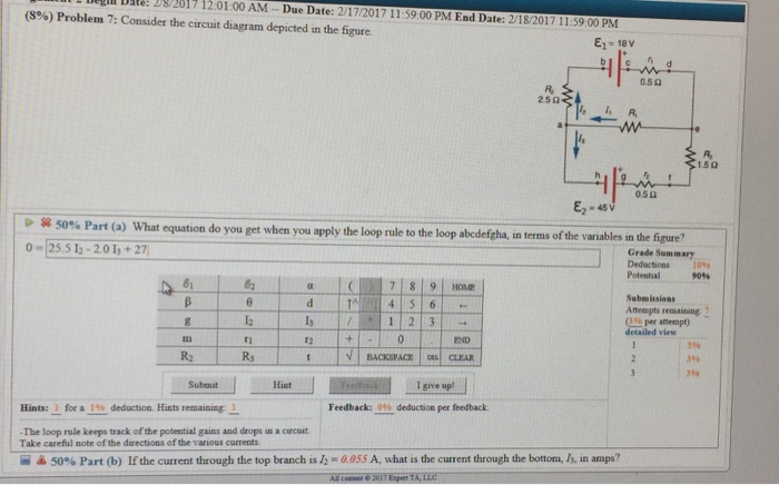
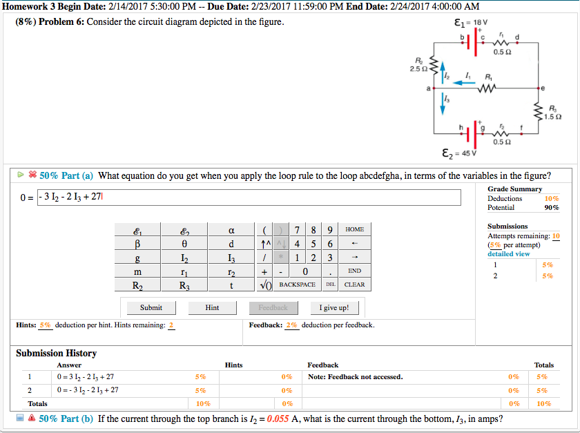
Solved (8%) Problem 7: Consider the circuit diagram ... Question: (8%) Problem 7: Consider the circuit diagram depicted in the figure E1 = 18V 0.5 R 250- " R w F 15 Al 0.50 Ez as d A 50% Part (a) What equation do you get when you apply the loop rule to the loop abcdefgha, terms of the variables in the figure? Grade Summary Deductions Potential 1004 O 0 G B 8 a d 13 12 t 7 8 9 45 6 12 3 Submissions ...
Applied Sciences | Free Full-Text | Parametric PSpice Circuit ...
Consider the mechanical system depicted in Figure CP24The ... The circuit diagram is shown in Figure P2.20(a), and the small-signal model is shown in Figure P2.20(b).This circuit uses an FET and provides a gain of approximately unity. Assume that R2 >> R1 for biasing purposes and that Rg >> The circuit shown in Figure P2.48 is called a lead-lag filter.

Circuit diagram - Wikipedia
Solved (13%) Problem 5: Consider the circuit diagram - Chegg Transcribed image text: (13%) Problem 5: Consider the circuit diagram depicted in the figure. E1 = 18V 0.52 RE 2.50 I, R e R 0.522 E-45V 50% Part (a) What ...
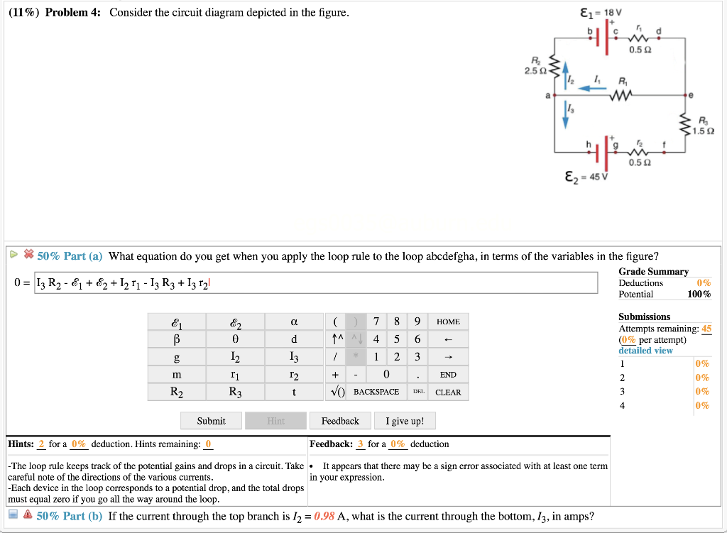
Solved (11%) Problem 4: Consider the circuit diagram | Chegg.com
PDF Chapter 2. Convolutional Codes 2.1 Encoder Structure The state diagram shows the state information of a convolutional encoder. The state information of a convolutional encoder is stored in the shift registers. Figure 2.4 shows the state diagram of the encoder in Figure 2.2. 1 0 0 1 0 0 1 1 0/00 1/11 0/10 1/01 1/10 0/01 1/00 0/11 Figure 2.4: State diagram representation of the encoder in Figure 2.2.
Low-Voltage GaN FETs in Motor Control Application; Issues and ...
Exercise 2 Consider the feedback system depicted in the ... Exercise 2: Consider the feedback system depicted in the figure below a. Compute the closed- loop transfer function using the 'series' and 'feedback' functions b. Obtain the closed- loop system unit step response with the 'step' function and verify that final value of the output is 2/5. 52 Lab Experiment 5: Block Diagram Reduction ...
Negative-resistance models for parametrically flux-pumped ...
Consider a simple RC circuit as shown in Figure 1 .Process ... Consider a simple RC circuit as shown in Figure 1. Process 1: In the circuit the switch S is closed at t = 0 and the capacitor is fully charged to voltage V 0 (i.e., charging continues for time T > > RC). In the process some dissipation (E D ) occurs across the resistance R.
Sustainability | Free Full-Text | A Comparative Study on the ...
PDF Question 1 — Equivalent Circuits The Thevenin equivalent circuit is obtained after transforming the current source into a´ voltage source V(s) = Z(s)I(s) = RCv c(0) 1+sRC. This sequence of transformations is shown in Figure 3. Question 2 — Laplace domain circuit analysis Figure 4: RC circuit for Laplace analysis. Part (i) [3 marks] Consider the circuit depicted in Figure 4 ...

figure . (25%) Problem 2: Consider the circuit diagram in the ...
Solved > Question Consider the circuit diagram depicted in ... What equation : 646641. Consider the circuit diagram depicted in the figure. What equation do you get when you apply the loop rule to the loop abcdefgha, in terms of the variables in the figure? 0 = If the current through the top branch is I_2 = 0.69 A, what is the current through the bottom, I_3, in amps?
Learn About Three-Op Amp Instrumentation Amplifiers ...
Consider the circuit diagram depicted in the figure. a ... Consider the circuit diagram depicted in the figure. a. What equation do you get when you apply the loop rule to the abcdefgha, in terms of the variables in the figure?
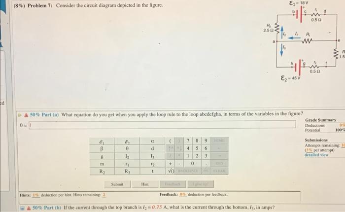
Solved (8%) Problem 7: Consider the circuit diagram depicted ...
Consider the circuit shown in the figure below : All the ... Consider the circuit shown in the figure below : All the resistors are identical. The ratio I/I' is (A) 8 (B) 6 (C) 5 (D) 4

Neural circuit diagrams | Nature Methods
Consider the circuit shown in the figure. All the ... Click here👆to get an answer to your question ️ Consider the circuit shown in the figure. All the resistors are identical. Find the ratio II' .
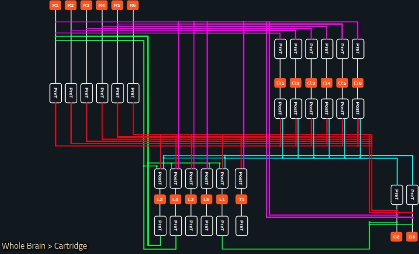
Accelerating with FlyBrainLab the discovery of the functional ...
Again, consider the cooling of the square plastic sheet of ... This is depicted in Figure(a). The plastic surface is at T_{s}. The sheet dimension is again L × L. Assume that the sheet can be treated as a vertical, semi-infinite plate (i.e., neglecting the end effect due to finite length) and treat the thermobuoyant flow and heat transfer accordingly. (a) Draw the thermal circuit diagram.

10) Problem 1 Consider the circuit diagram depicted in the ...
Answered: 34. 35. Calculate the secondary voltage… | bartleby Q: ENL Consider the circuit diagram depicted in the figure. E- 18 V 0.50 250 ww 1.50 0.50 (a) What equa... E- 18 V 0.50 250 ww 1.50 0.50 (a) What equa... A: Click to see the answer
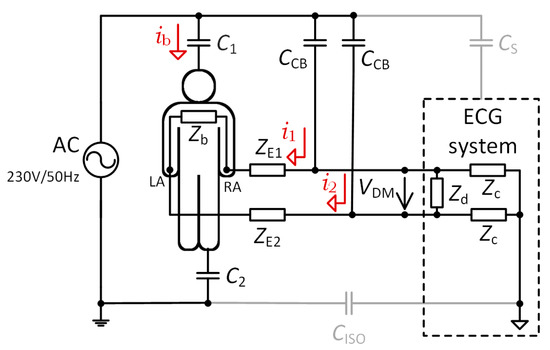
Sensors | Free Full-Text | Two-Electrode ECG for Ambulatory ...
Answered: Consider the network depicted in the… | bartleby Consider the network depicted in the following figure, and determine the equivalent impedance seen looking into the open terminals if w = 15 rad/s 2 mF 20 N : 25 Ω 55 Ω 2H Oa. 12.482 + J 3.864 0 Ob. 8.482 + J 7.864 2 Oc. 14.482 + J 1.864 2 Od. 10.482 + J 5.864 2 ell. check_circle.

Consider the circuit diagram depicted in the figure
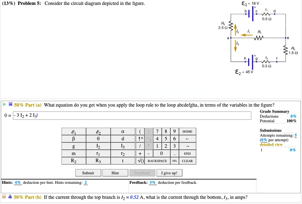
SOLVED:(13% ) Problem 5: Consider the circuit diagram ...

Electrical Characterization of Organic and Perovskite Solar Cells
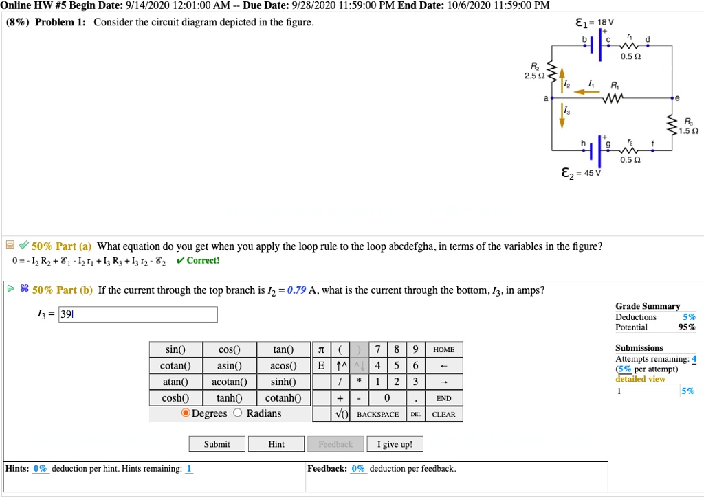
SOLVED:Online HW #5 Begin Date: 9/14/2020 12.01.00 AM Due ...

Learn About Three-Op Amp Instrumentation Amplifiers ...

10) Problem 1 Consider the circuit diagram depicted in the ...

Applying the Laplace Transform in LTspice to Model Transfer ...
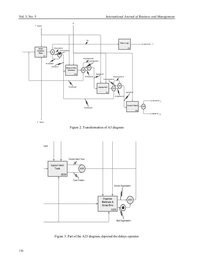
Idef 0 language_introduction
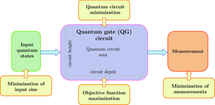
Quantum circuit design for objective function maximization in ...

Central pattern generating networks in insect locomotion ...
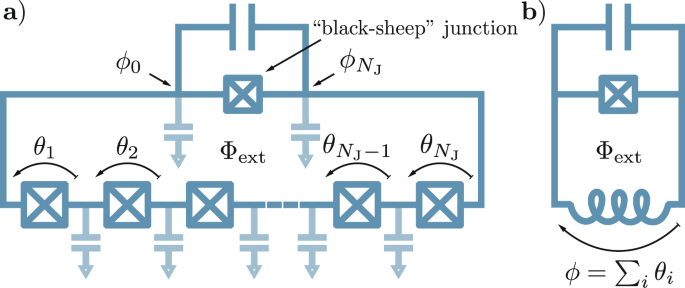
Efficient modeling of superconducting quantum circuits with ...
RETs deliver efficient 48 V digital switching | Efficiency Wins

Conventional three‐electrode dielectric cell (figure adapted ...
Solved Consider the circuit diagram depicted in the figure ...

Using power MOSFETs in DC motor control applications | Nexperia
Solved L 2017 12:01:00 AM Due Date: 2/17/2017 11:59:00 PM ...

The Nyquist Diagram for Electrical Circuits | Zurich Instruments

The Nyquist Diagram for Electrical Circuits | Zurich Instruments

Continuous sulfonation of hexadecylbenzene in a microreactor

Modular Network between Postrhinal Visual Cortex, Amygdala ...
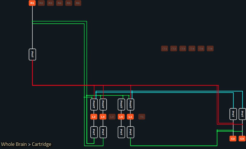
Accelerating with FlyBrainLab the discovery of the functional ...

The Nyquist Diagram for Electrical Circuits | Zurich Instruments

10) Problem 1 Consider the circuit diagram depicted in the ...
Solved (10%) Problem, 7: Consider the circuit diagram | Chegg.com
Solved Consider the circuit diagram depicted in the figure ...
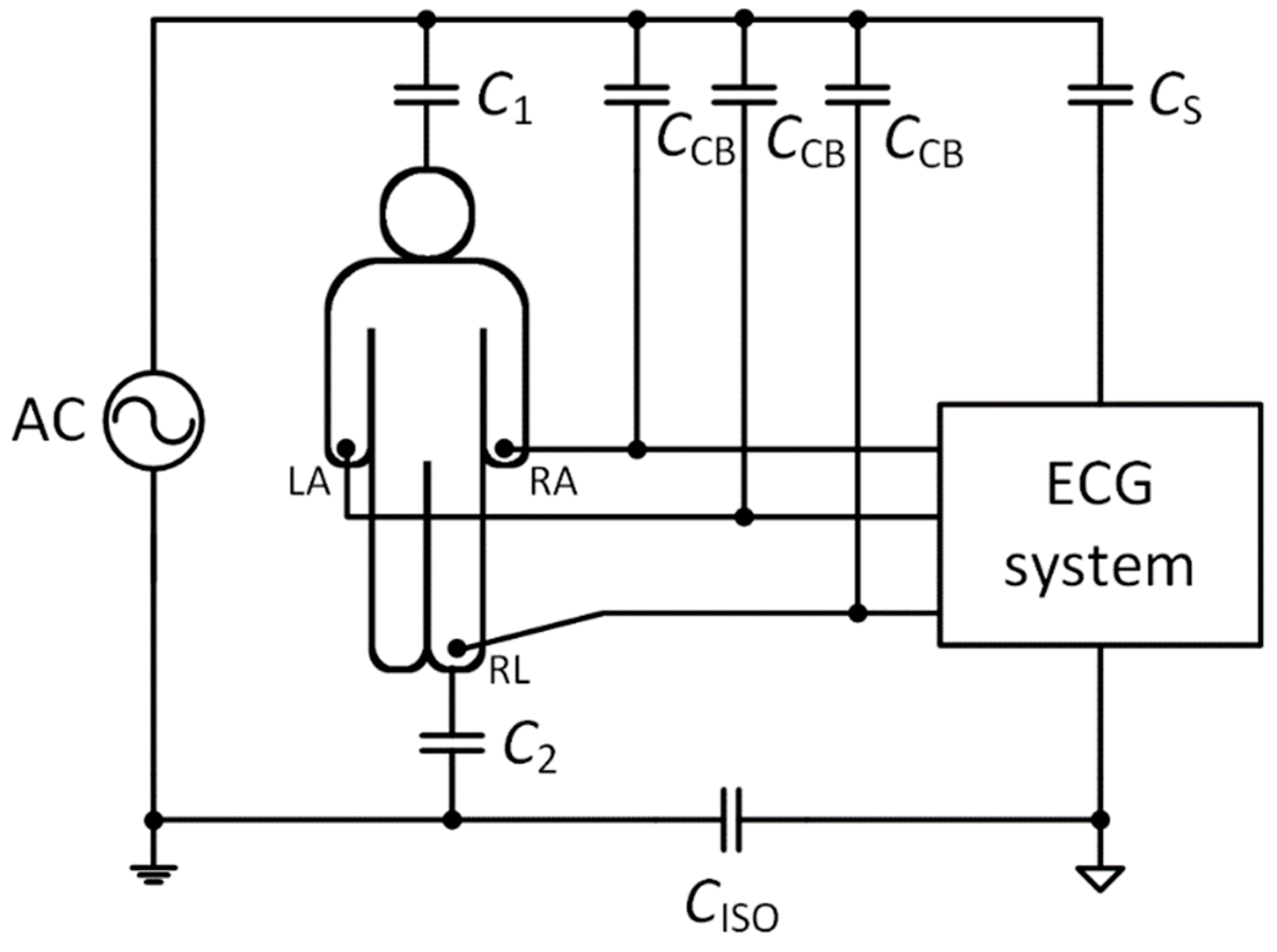
Sensors | Free Full-Text | Two-Electrode ECG for Ambulatory ...
0 Response to "42 consider the circuit diagram depicted in the figure"
Post a Comment