40 Pilot Brake Controller Wiring Diagram
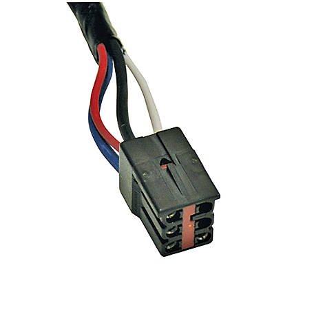
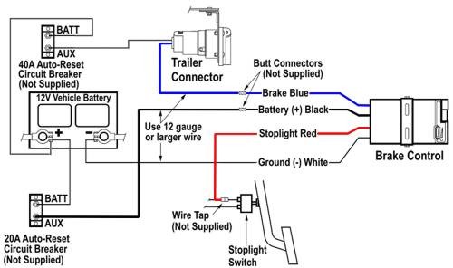
PDF Brake Control Wiring Diagram - AnythingTruck.com Wiring Legend BLACK Wire (Positive Battery) WHITE Wire (Negative Battery) RED Wire (cold side of stoplight switch) BLUE Wire (brake output to trailer) 1. The WHITE (-) wire must be connected to a known ground. 2. CAUTION Inadequate grounding may cause intermittent braking or lack of sufficient voltage to trailer brakes. The Trailer Brake Controller Wiring Diagram - Studying Diagrams Pilot Trailer Brake Controller Wiring DiagramThis page has wire diagrams for many electric options including wires for trailer lights brakes alt power and connectors. Wiring Diagram For Reese Pilot Brake Controller. It can be made use of as a resource of information or as a tool for building. Ford Trailer Brake Controller Wiring Diagram Collection.
Pro Series Pilot® Brake Control, for 1 to 3 Axle Trailers ... Pilot® Brake Control, for 1 to 3 Axle Trailers, Timed Actuated. Pilot has a dark, smoke lens that is ideal for direct light applications, creating optimum visibility to read the large, two-digit display. Pilot has flexible mounting options and can be installed in any direction. Our microprocessor allows you the ability to read the display even ...

Pilot brake controller wiring diagram
CURT Group OrderHub 301 Moved Permanently. nginx Pilot Electronic Brake Control | U-Haul The Pilot brake control part 13523 will work mounted at any angle, even up side down. -SAVANNAH 6/17/2016 8:13:46 AM. Do you have the electric brake control in the stores or would it have to be ordered ... are brake controller wiring adapters available for 2014 dodge caravan Wire Color Codes on Pilot # 80550 Brake Controller ... The wire color codes on the Pilot Brake Controller are as follows: the red wire interfaces with the vehicle brake system by tapping into the cold side of the brake stoplight switch located at the top of the brake pedal. The best way to locate the correct circuit to tap into would be to use a circuit tester like part # 40376.
Pilot brake controller wiring diagram. Installing Hayman Reese Brake Controllers and Wiring ... Presented by Hayman Reese technical towing expert Gary Gardiner, watch the typical installation process of Hayman Reese Brake Controllers, including end-to-e... › 32475947 › Schneider_Electric(PDF) Schneider Electric Wiring Diagram Book - Academia.edu This book contains examples of control circuits, motor starting switches, and wiring diagrams for ac manual starters, drum switches, starters, contactors, relays, limit switches, and lighting contactors. How To Install A Electric Trailer Brake Controller On A ... The wiring diagram to the right is a basic brake controller hook up. The wiring harness shown is typical of any electric brake control installation. Some newer vehicles provide their own brake control jumper harness which makes the install a plug and play affair. When you purchase a brake controller and install it on a vehicle without a factory ... schematron.org › western-star-4900-wiring-diagramWestern Star 4900 Wiring Diagram - schematron.org Feb 11, 2018 · Western Star Truck Wiring Diagram Engine Paper Used Op Rr7 Relay Diagram I m working on Western Star FA Looking for a c clutch Source. Western Star. In mid , the model suffix changed from "FA" to "SF" for models with set-forward axles. 1 for a charging circuit wiring diagram.
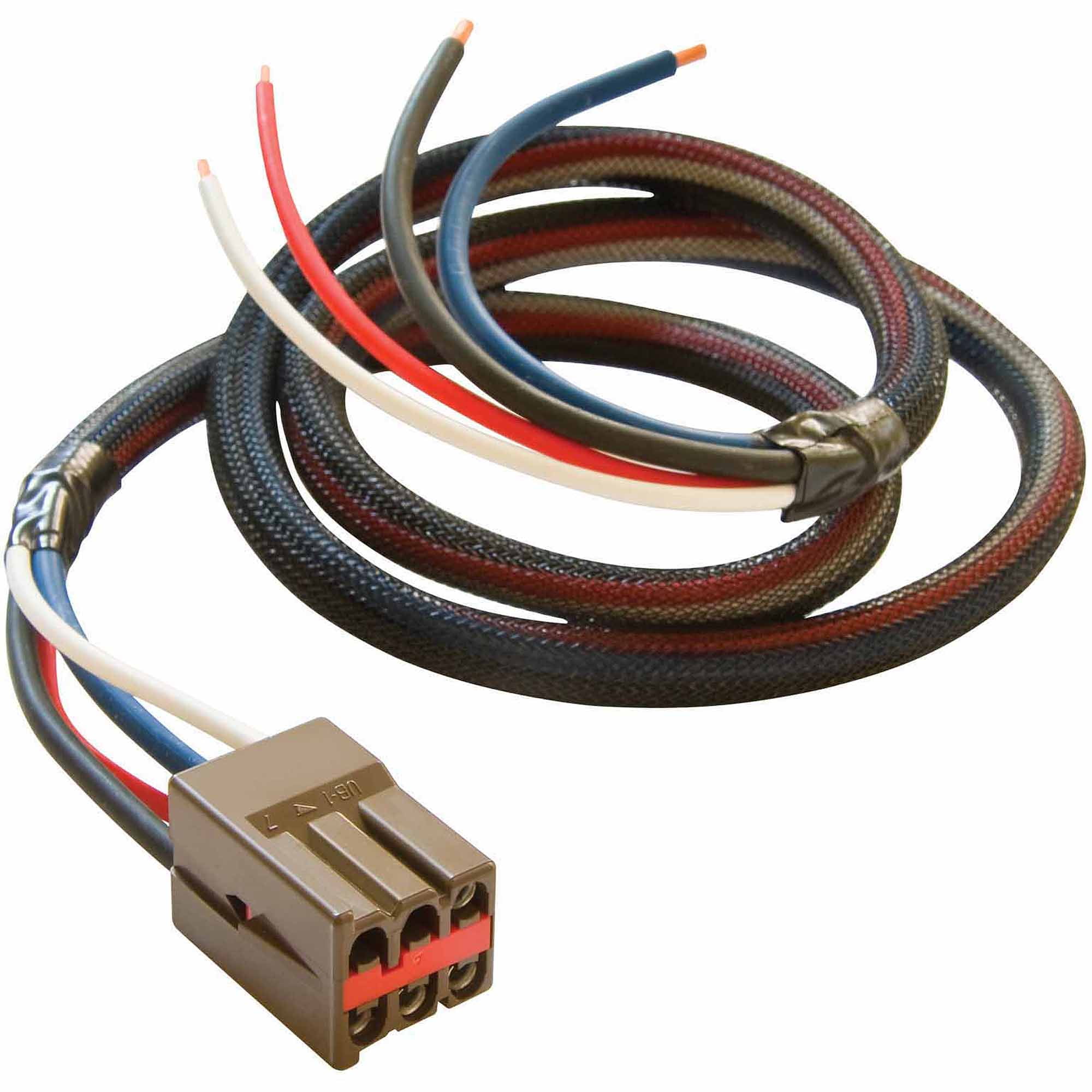
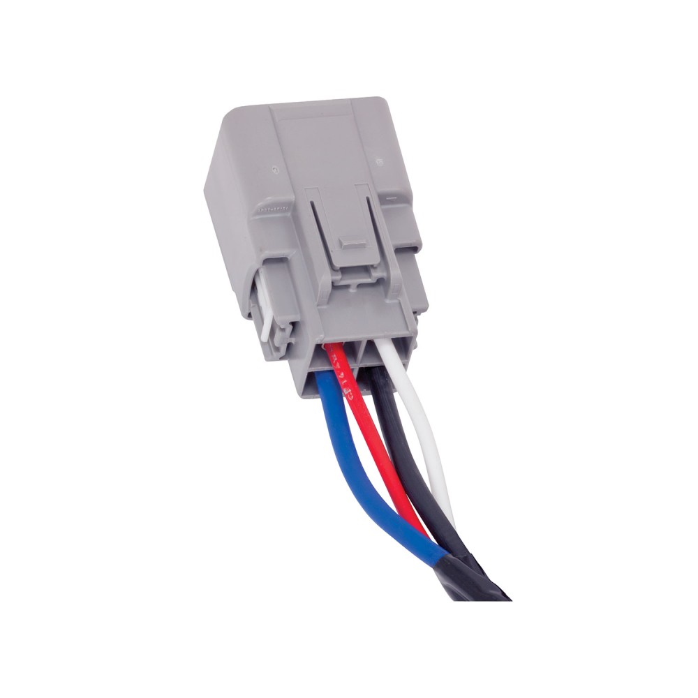
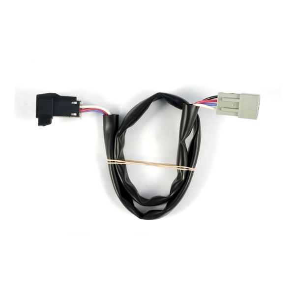
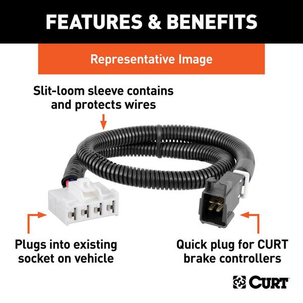
Reese Electrical Brake Control Systems Wiring Kit for 2 to 4 Brake Control Systems, Includes 25 ft. 12-2 Duplex Wire, 20 Amp Circuit Breaker and Attaching Terminals. $25.25. 20506. Wiring Kit for 6 to 8 Brake Control Systems, Includes 25 ft. 12-2 Duplex Wire, 30 Amp Circuit Breaker and Attaching Terminals. $49.45. Wiring Instructions for Pilot Trailer Brake Control, Part ... The blue wire carries the brake controller output voltage, the white wire provides the ground connection and is usually ran to the negative battery terminal, the black wire is the 12-volt power supply, and the red wire typically connects to the brake stoplight switch located above the brake pedal. This connection activates the trailer brakes once the brake pedal is applied. Reese brake controller instructions - United States ... Nov 24, 2018 · Reese Trailer Brake Controller Wiring Diagram - hayman reese trailer brake controller wiring diagram, reese electric brake controller wiring diagram, reese pilot trailer brake controller wiring diagram, People today comprehend that trailer is a vehicle comprised of very complicated mechanisms. This vehicle is designed not just ... › brake-controllers-vehicleTrailer Brake Controllers and Vehicle Wiring Curt brake controller adapter harness is designed to allow competitor brake controller harnesses to be used with CURT trailer brake controllers. It is compatible with Tekonsha, Reese, Draw-Tite and Pro Series vehicle-specific harnesses.
› Content › ImagesElite Electric Trailer Brake Controller - Redarc Electronics 2.2 - Wiring the brake controller 6 2.2.1 Red Wire (Vehicle Brake light) Connection 6 2.2.2 Wiring Diagrams 7 2.3 - Mounting the Remote Head 8 2.4 - Active Calibration 9 3 - Operation 10 3.1 - Adjusting the Braking Force 10 3.2 - Manual Override 10 3.3 - Operating Modes 11 3.3.1 - Proportional Mode (Blue LED) 11 3.3.2 - User Controller Mode ... Reese Pilot Wiring Diagram - schematron.org The REESE Towpower PILOT digital brake control designed for one to three for quick installation, just get the right harness and wiring is just plug and go. DRAW-TITE VEHICLE BRAKE CONTROL WIRING DIAGRAM. HONDA - Car PDF Manual, Wiring Diagram & Fault Codes DTC Some HONDA Car Manuals PDF & Wiring Diagrams above the page - Civic, CR-V, Fit, Ridgeline, S2000, Accord, Odyssey, Element, Pilot; Honda Car EWDs.. In 1946, the Japanese automobile company Honda was created. Its founder Soichiro Honda did not have the necessary engineering education, but he compensated for all the gaps with risk and accurate instinct. PDF PILOT INSTALLATION - TruckSpring wiring brake control. Keep these instructions with the brake control for future reference. Installation for Pilot Brake Control B C D E A NOTE: Display shows tenths of a volt up to 9.9. After 9.9 the display shows whole digits only. B A C NOTE: Drilling or use of longer screws may damage unit. B A C D NOTE: Check behind dash for wires, etc. before drilling.
Husky Towing 31899 Quest Proportional Trailer Brake Controller
Electrical Wiring - Reese Towpower Electrical Wiring Trailers require electrical hook-ups that make towing safer for you and others on the road. In fact, while each state has its own laws and regulations governing everything from size limits to weight restrictions, the one thing they all have in common is that your trailer must be wired for tail lights, brake lights and turn ...
Reese Towpower Pilot Digital Brake Control - Walmart.com
Pilot Brake Control for 1-3 Axle Trailers Pro Series Pilot® Brake Control for 1 to 3 Axle Trailers. Product Features. Pilot has a dark, smoke lens that is ideal for direct light applications, creating optimum visibility to read the large, two-digit display. Pilot has flexible mounting options and can be installed in any direction. Our microprocessor allows you the ability to read the ...
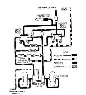
POWER BRAKE CONTROL VALVE SYSTEM
Brake Force Electric Brake Controller Wiring Diagram ... Collection of prodigy brake controller wiring diagram. The red stoplight wire must be connected to the cold side of the brake pedal stoplight switch. If your vehicle came equipped with a factory tow package brake control function wires may exist under the vehicle. The following diagram is a general guide for wiring common brake controllers into cars.

Trailer Hitch Hidden Hitch Electric Trailer Brake Controls
Wiring diagram for brake controllers | Trailer Spares ... A brake controller wiring installation kit makes light work! The following diagram is a general guide for wiring common brake controllers into cars. Please ensure you have the correct gauge wire and we do recommend you use an auto-electrician to wire the brake controller into your car.
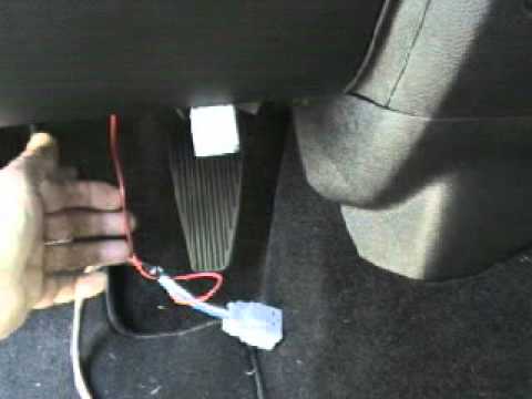
Brake controller install - 2014 Ram 1500
Wiring Diagram For Reese Pilot Brake Controller PILOT Brake Controller. locate the slide knob and power knob (items A and B in the linked instructions' diagram). Pilot Brake Electronic Brake Controller - Time Delayed Wiring Instructions for Pilot Trailer Brake Control, Part # · What Can Cause Troubleshooting a Reese Pilot Brake Controller that Says It's Connected all the Time.

Pilot Automotive Wiring Harness Kit w/ Wireless Remote ...
› peugeot-fault-codesPEUGEOT Fault Codes DTC - Car PDF Manual, Wiring Diagram ... Jan 07, 2017 · Hello nice to meet you I got problem with my R300 BT (Radio), and need R300 BT wiring diagram for opel astra K 2017 sport tourer to repair it, can you plaeas send the diagram or pins info from R300 BT wiring diagram opel. Thnx ikramidis@hotmail.com #159. Ghaly (Saturday, 12 September 2020 16:36)

Universal Installation Kit for Trailer Brake Controller - 7 ...
Pilot-Rc Electric Retract Landing Gear Controller - MANUAL Locate on the Electric Retract Landing Gear Controller the Radio inputs for Gear and Brake, and connect to the corresponding receiver channels set up in step 1 using the patch leads provided. Connect the Retract leads and Brake leads to the Electric Retract Landing Gear Controllers corresponding outputs.

Reese Pilot Brake Controller, Black (74378)
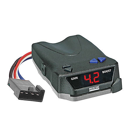
› Trailer-Brake-ControllerTekonsha Prodigy P3 Trailer Brake Controller - 1 to 4 Axles ... We have the T-One Wiring Kit # 118286 from Tekonsha which comes with everything you need to install a fully-functioning 7-Way connector on your 2020 Honda Pilot. Then for a brake controller I highly recommend the Tekonsha Prodigy P3 # 90195 which installs to the plug under your driver's side dash with the adapter # 3070-P.
Honda Ridgeline Brake Controller Installation Instructions
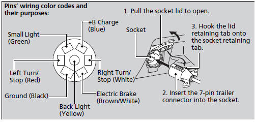
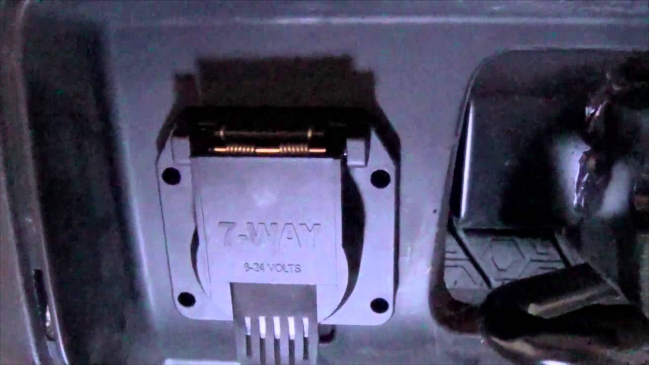
Pilot Trailer Brake Controller Wiring Diagram - Trailer ... 7-Pin Connector. This Pilot Trailer Brake Controller Wiring Diagram model is much more appropriate for sophisticated trailers and RVs. It can transfer power better therefore the connector is suggested for higher-level electric in the vehicle. Here's the diagram for 7-pin connector. White Pin to your floor.
Reese Pilot Trailer Brake Control for 15-22 RAM 1500 2500 ...
Ford Trailer Brake Controller Wiring Diagram - Wirings Diagram Ford Trailer Brake Controller Wiring Diagram - 2001 f250 trailer brake controller wiring diagram, 2005 ford f250 factory trailer brake controller wiring diagram, 2005 ford f250 trailer brake controller wiring diagram, Every electrical arrangement consists of various distinct parts. Each component should be placed and linked to other parts in particular manner.
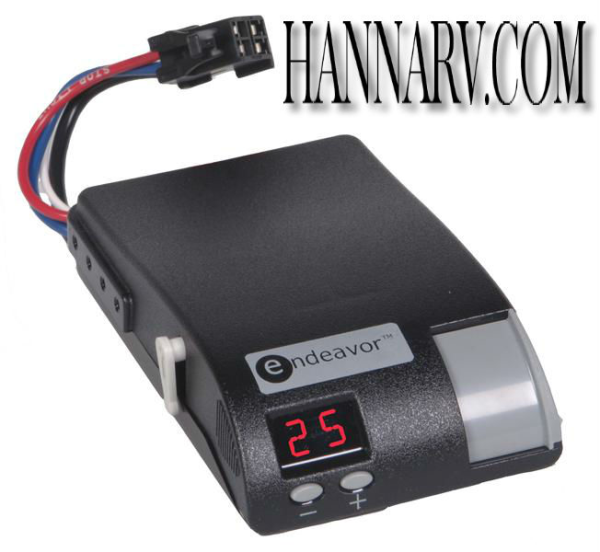
Hayes 81770 Endeavor Digital Proportional Trailer Electric ...
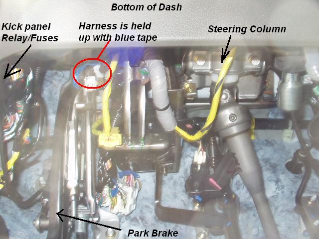
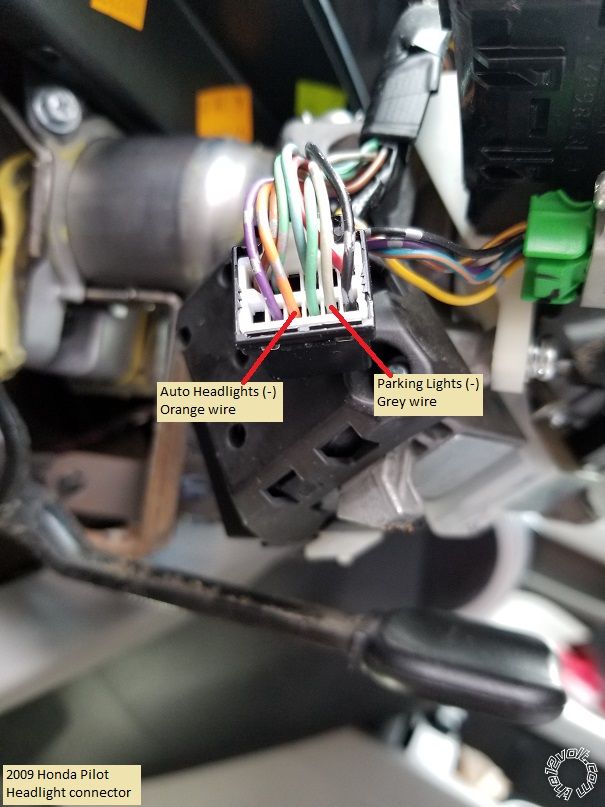
Towing - Brake Controller Wiring | Honda Pilot - Honda ... With the 2016 pilot wiring harness option you get a plug under the dash on the left sidewall that a 2012-2016 adapter plug will fit, also supplied with the harness kit.This adapter plug needs to be wired to the plug for the back your particular brand of electric brake controller which is supplied by the brake controller company.

PBL90 Brake Control | The Railway Technical Website | PRC ...
› faq-etbc7Brake Controller 7- and 4-Way Installation Kit (ETBC7 ... 10. Using a butt connector, connect the blue wire coming out of the brake controller to the white brake wire from the duplex cable that was routed through the firewall. 11. Mount the 20-amp (or 30-amp; see brake controller instructions) and the 40-amp circuit breakers in a safe location under the hood.
Towing Preparation :: Towing a Trailer :: Driving :: Honda ...
Wire Color Codes on Pilot # 80550 Brake Controller ... The wire color codes on the Pilot Brake Controller are as follows: the red wire interfaces with the vehicle brake system by tapping into the cold side of the brake stoplight switch located at the top of the brake pedal. The best way to locate the correct circuit to tap into would be to use a circuit tester like part # 40376.

Reese Towpower 7805011 Brake Control Wiring Harness
Pilot Electronic Brake Control | U-Haul The Pilot brake control part 13523 will work mounted at any angle, even up side down. -SAVANNAH 6/17/2016 8:13:46 AM. Do you have the electric brake control in the stores or would it have to be ordered ... are brake controller wiring adapters available for 2014 dodge caravan
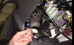
Where is Brake Controller Install Port on 2016 Honda Pilot ...
CURT Group OrderHub 301 Moved Permanently. nginx

How to Install Your Brake Control
trailer brake controller plug-in location??? | Honda Pilot ...

Brake Controller | Nissan Titan Forum
trailer brake controller plug-in location??? | Honda Pilot ...
ATS CO-PILOT INSTALLATION MANUAL Pdf Download | ManualsLib
Hopkins Impulse Brake Control
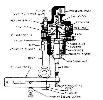
POWER BRAKE CONTROL VALVE SYSTEM

Brake Controller Wiring Harnesses – REDARC

Best Trailer Brake Controllers - Forbes Wheels
Reese Towpower Towing Brake Control Harness, 18 in., 7805411 ...
Brake Controller Installation: Starting from Scratch ...

2003 Honda Pilot. Brake Lamp dash indicator just came on ...
2009-2016 Honda Pilot Remote Start w/Keyless Entry Pictorial
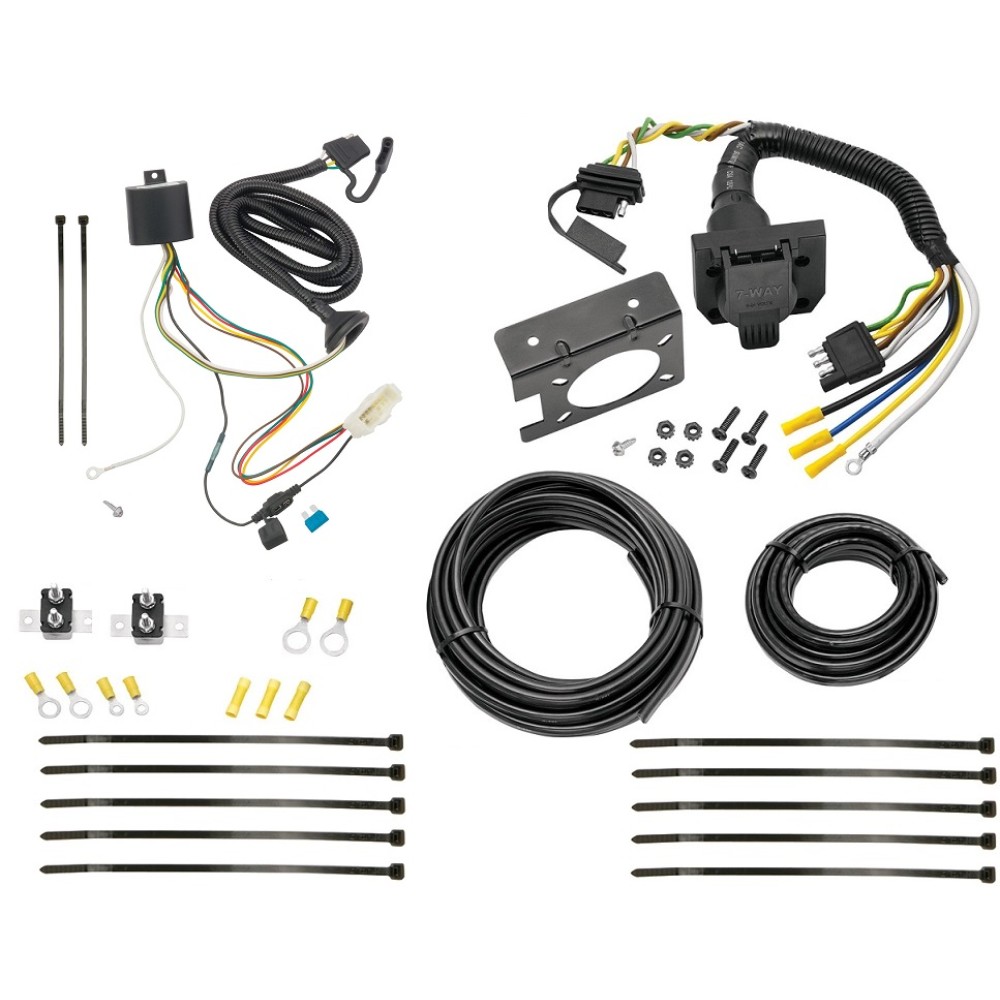
Trailer Hitch 7 Way RV Wiring Kit For 16-22 Honda Pilot Plug ...
Factory installed towing pkg - wiring problem | Honda Odyssey ...

OEM Connector-Acura Vehicles (RV 81A-C-10-28P)
Reese Towpower BRAKE-EVN Trailer Brake Controller, Proportional, 1 to 4 Axles, 8508211

Portable Electric Brake Controller | GET TOWING IN 5 MINUTES ...
Curt Brake Controller Wiring Harness 51392
Wiring Instructions for Pilot Trailer Brake Control, Part ...

Reese Towpower | 2 - Plug Adapters

Brake Controller Wiring Harnesses – REDARC
CURT Trailer Brake Controller Harness, Select Honda Passport ...
2013 Honda Pilot Wiring Harness Install - YouTube
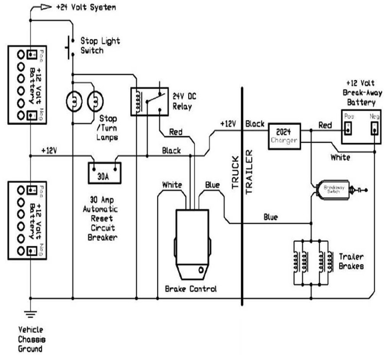
Installing Electric Brake Controls on 24 Volt Vehicles ...
0 Response to "40 Pilot Brake Controller Wiring Diagram"
Post a Comment