40 franklin electric motor wiring diagram
Franklin Electric Motor Wiring Diagram from static-cdn.imageservice.cloud Print the cabling diagram off and use highlighters in order to trace the signal. When you use your finger or follow the circuit together with your eyes, it’s easy to mistrace the circuit. 1 trick that I actually 2 to print out exactly the same wiring plan off twice. Dec 29, 2019 · Franklin Electric Motor Wiring Diagram. By Prof. Images December 29, 2019 Post a Comment. Franklin Electric 5800060100 Pumptec Plus Motor Protection Device 230v 1 Phase 1 2 5 Hp Franklin Electric Submersible Pump Manual 2hp 230v Standard Control Box Electric Motor Hp Chart Yobi Karikaturize Com Aim Manual Page 54 Single Phase Motors And Controls Electric Motor Wiring Diagram Capacitor Wiring Diagram Franklin Electric 220volt 1 6 Hp Motor 1306030100 Motors Franklin Electric Fan Motor Wiring ...
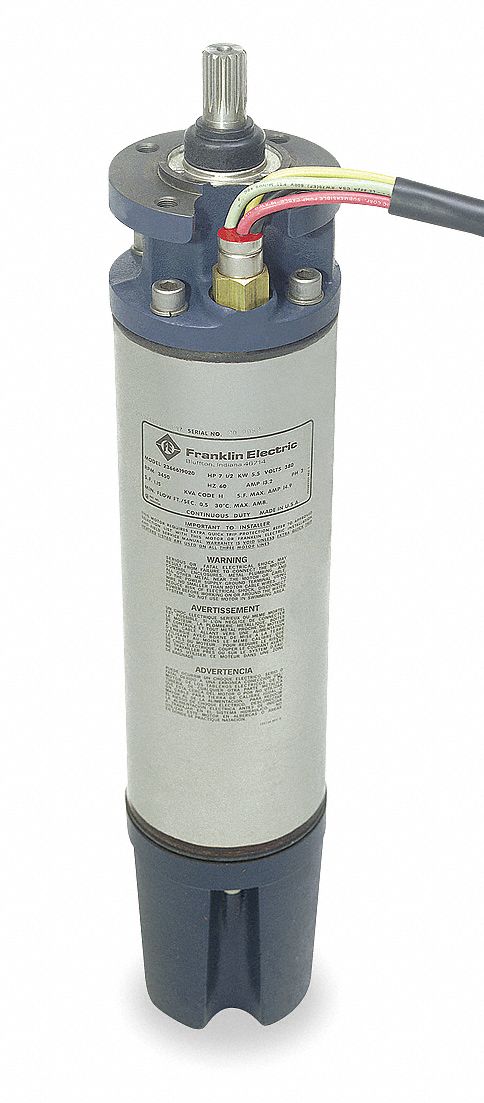
and directly from franklin electric. call franklin toll free 800-348-2420 for information. warning serious or fatal electrical shock may result from failure to connect the motor, control enclosures, metal plumbing, and all other metal near the motor or cable, to the power supply ground terminal using wire no smaller than motor cable wires.

Franklin electric motor wiring diagram
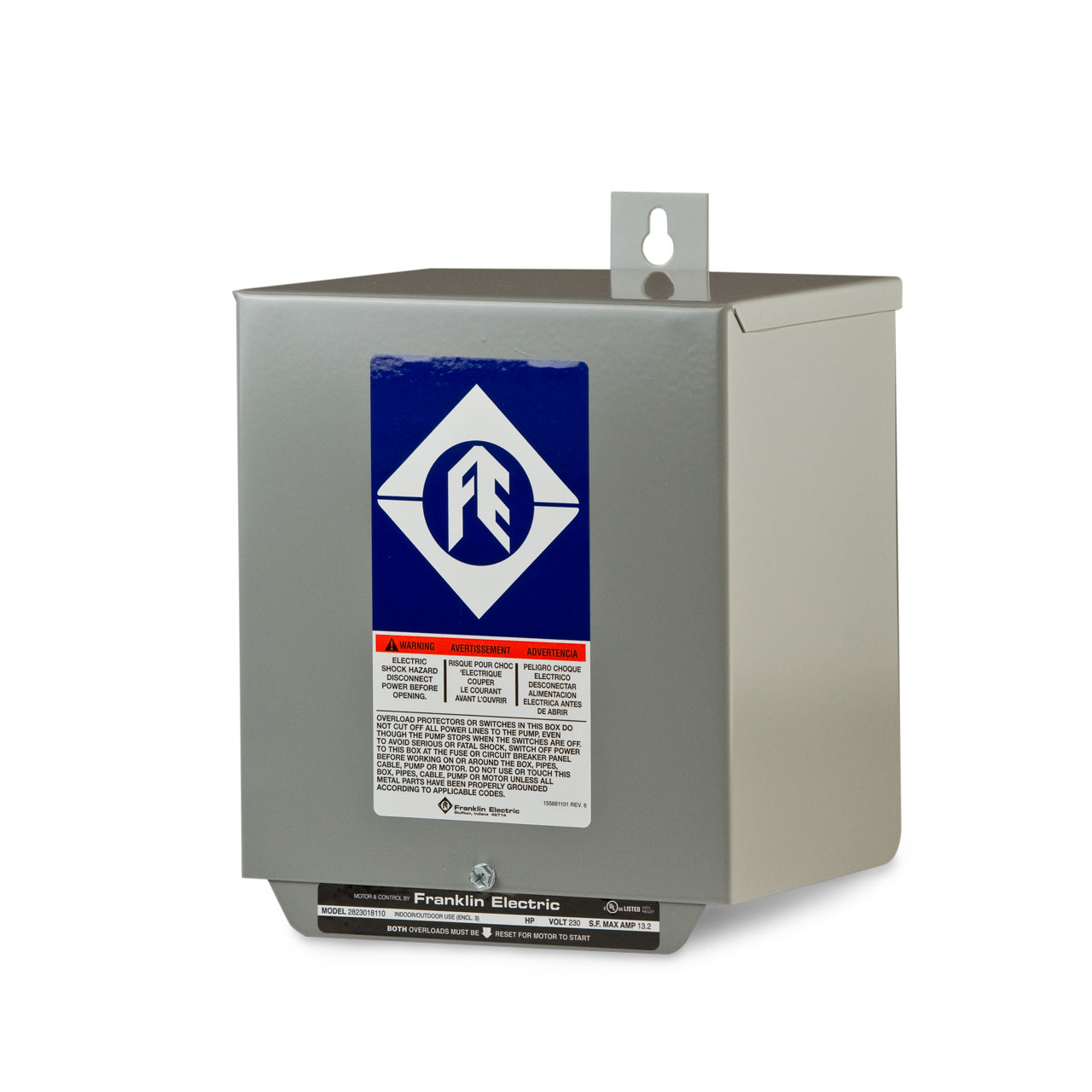
Control Box Wiring Diagrams (Continued) · 2 hp STANDARD 282 301 8110 · 2 hp DELUXE 282 301 8310 · 3 hp STANDARD 282 302 8110 · 3 hp DELUXE 282 302 8310. Franklin Electric Control Box Wiring Diagram – franklin electric control box wiring diagram, franklin electric qd control box wiring diagram, franklin electric well pump control box wiring diagram, Every electrical structure is composed of various distinct components. Each component ought to be placed and linked to other parts in particular way. If not, the structure … Franklin Electric Submersible Motor Control Wiring Diagram. Aim manual page 54 single phase motors and controls motor maintenance north america water franklin electric 55 56 57 53 qd control box 1 2 hp 115v 2801044915 submersible 0 5 1ph for 3 wire fec2801044915 21450890 4 super stainless pump 230v fec21450890 deluxe 18184 little giant wiring ...
Franklin electric motor wiring diagram. Franklin Qd Control Relay Wiring Diagram 09.11.2018 6 Comments In the case of Franklin Electric Control Boxes, there's much more to the a surge arrestor, protecting the QD Relay and the motor from electrical. Control Box Wiring Diagrams. 1/3 - 1 hp QD RELAY 10_ Sixth digit depends on hp. 1/2 - 1 hp CRC QD RELAY 40_ Sixth digit depends on . BLACK. 11.01.2021 · 3 Way Switch Wiring Diagram Home Electrical Wiring House Wiring Electrical Wiring . Single Phase Forward Reverse Motor Wiring Diagram 3 779x1024 On Single Phase Forward Reverse Motor Ac Capacitor Circuit Diagram Electric Motor . Led Light Bar Relay Wire Up At Wiring Diagram For 12v Led Lights In Motorcycle Wiring Light Switch Wiring 12v Led … Motor Maintenance » Single-Phase Motors and Controls (Page 54) Menu; Page 53; Page 54 Page 55 >> Control Box Wiring Diagrams (Continued) ... Franklin Electric Co ... Franklin Electric Motor Wiring Diagram Aim Manual Page 53 Single Phase Motors and Controls. Franklin Electric Motor Wiring Diagram Vk 9808 Wire Float Switch Wiring Diagram On 230v Single. Franklin Electric Motor Wiring Diagram Franklin Qd Control Box 1 2 Hp 115v. Franklin Electric Motor Wiring Diagram Mk 9547 Well Pump Wire Furthermore Franklin ...
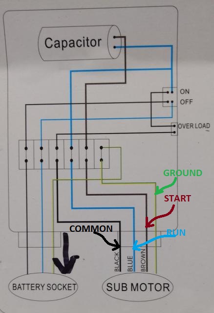
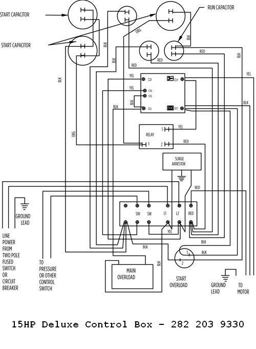
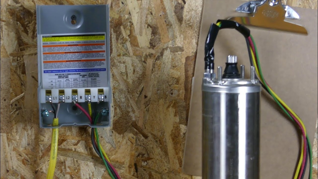
1. the distribution panel. The motor lead incorporates a green grounding conductor. 6. A 2-wire C1-Series has two power supply wires and one ground wire, and does not require a motor control box, since all electrical components are built inside the motor. FIGURE 1 shows a typical wiring diagram for a 2-wire installation. 7. 10.02.2018 · Franklin Electric Submersible Motor Wiring Diagram Franklin Electric 1/2 HP 10 GPM submersible water well pump you can just install a regular plug to the end of the wires and plug it in, but you will need to add. Franklin Electric control boxes are an integral part of a submersible motor power QD Submersible Motor Control Box HP. ficer of a General Electric … Control Box Wiring Diagrams (Continued) · 10 hp STANDARD - 282 202 9210 or 282 202 9230 · 10 hp DELUXE 282 202 9310 or 282 202 9330 · 15 hp DELUXE - 282 203 9310 ... 28.02.2021 · Franklin Electric Fan Motor Wiring Diagrams Wiring. Aim manual page 53 single phase motors and controls motor maintenance north america water franklin electric 1hp 230v qd control box 5hp deluxe 3 wire 55 1 hp submersible well pump wiring diagram p rail pickup vga diau tiralarc bretagne fr chevy dodyjm nescafe jeanjaures37 2823028110 standard …
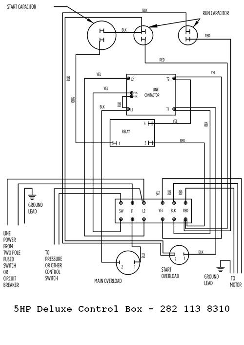
Franklin YouTube Page NSF/ANSI 61 Approvals Internet Minimum Advertised Price (iMAP) Policy. ... Motor Maintenance » Single-Phase Motors and Controls (Page 53) Menu; Page 52 ... Page 54 >> Control Box Wiring Diagrams. 1/3 - 1 hp QD RELAY 280 10_ 4915 Sixth digit depends on hp. 1/2 - 1 hp CRC QD RELAY 282 40_ 5015 Sixth digit depends on hp ... and directly from franklin electric. call franklin toll free 800-348-2420 for information. warning serious or fatal electrical shock may result from failure to connect the motor, control enclosures, metal plumbing, and all other metal near the motor or cable, to the power supply ground terminal using wire no smaller than motor cable wires. Control Box Wiring Diagrams (Continued) · 5 hp STANDARD - 282 113 8110 · 5 hp DELUXE - 282 113 8310 or 282 113 9310 · 7.5 hp STANDARD - 282 201 9210 · 7.5 hp DELUXE ... We offer pumps, motors, drives, and controls for use in a wide variety of residential, commercial, agricultural, industrial, and municipal applications. Moving Forward Together. Complete water and fueling solutions, comprised of world-class brands and services that you trust: Franklin Electric is your partner to keep moving forward.
Fuentes
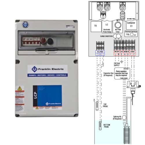
Congratulations on your purchase of a Franklin Electric pump protection system. Pumptec-Plus is the most sophisticated pump protection system on market today. It is designed to work on any 230 VAC single phase induction motor (PSC, CSCR, CSIR and split phase) ranging in size from 1/2 to 5 horsepower.

AIM Manual - Page 53 | Single-Phase Motors and Controls ...
Franklin Electric Submersible Motor Control Wiring Diagram. Aim manual page 54 single phase motors and controls motor maintenance north america water franklin electric 55 56 57 53 qd control box 1 2 hp 115v 2801044915 submersible 0 5 1ph for 3 wire fec2801044915 21450890 4 super stainless pump 230v fec21450890 deluxe 18184 little giant wiring ...

AIM Manual - Page 54 | Single-Phase Motors and Controls ...
Franklin Electric Control Box Wiring Diagram – franklin electric control box wiring diagram, franklin electric qd control box wiring diagram, franklin electric well pump control box wiring diagram, Every electrical structure is composed of various distinct components. Each component ought to be placed and linked to other parts in particular way. If not, the structure …

AIM Manual - Page 55 | Single-Phase Motors and Controls ...
Control Box Wiring Diagrams (Continued) · 2 hp STANDARD 282 301 8110 · 2 hp DELUXE 282 301 8310 · 3 hp STANDARD 282 302 8110 · 3 hp DELUXE 282 302 8310.
Column-mounted wiper switch operation

AIM Manual - Page 54 | Single-Phase Motors and Controls ...
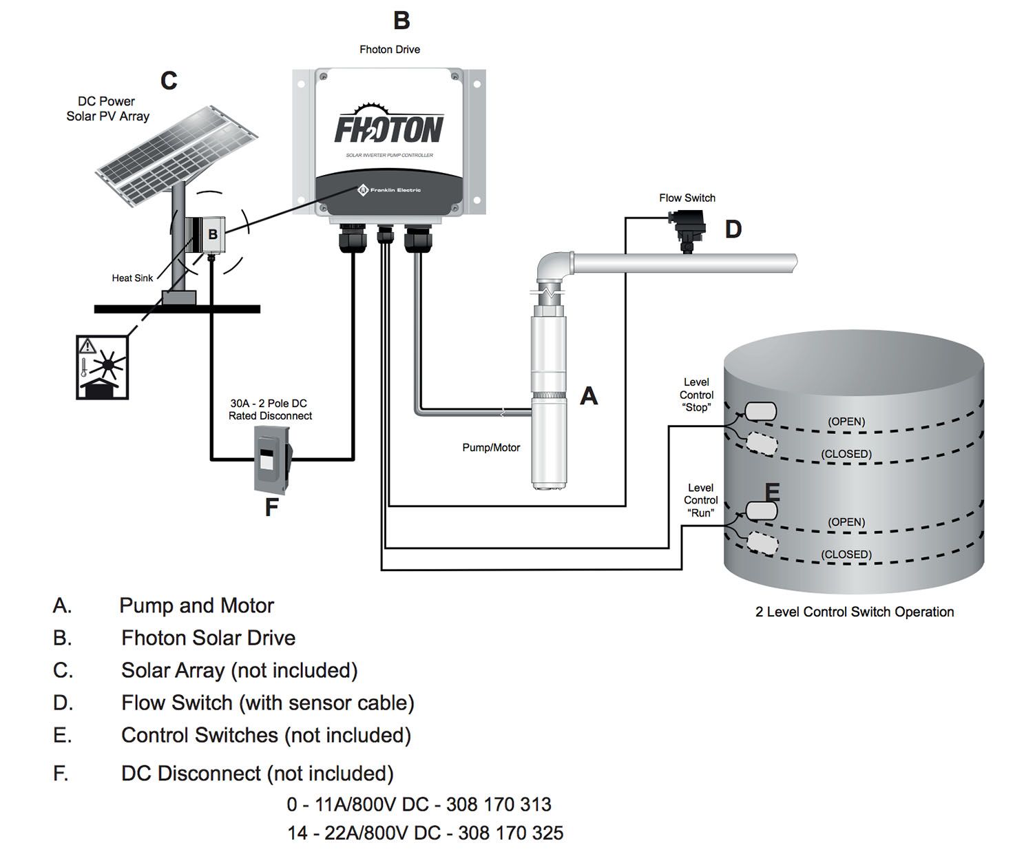
Submersible solar pump - Fhoton SolarPAK

How to Install and Wire a Pressure Switch
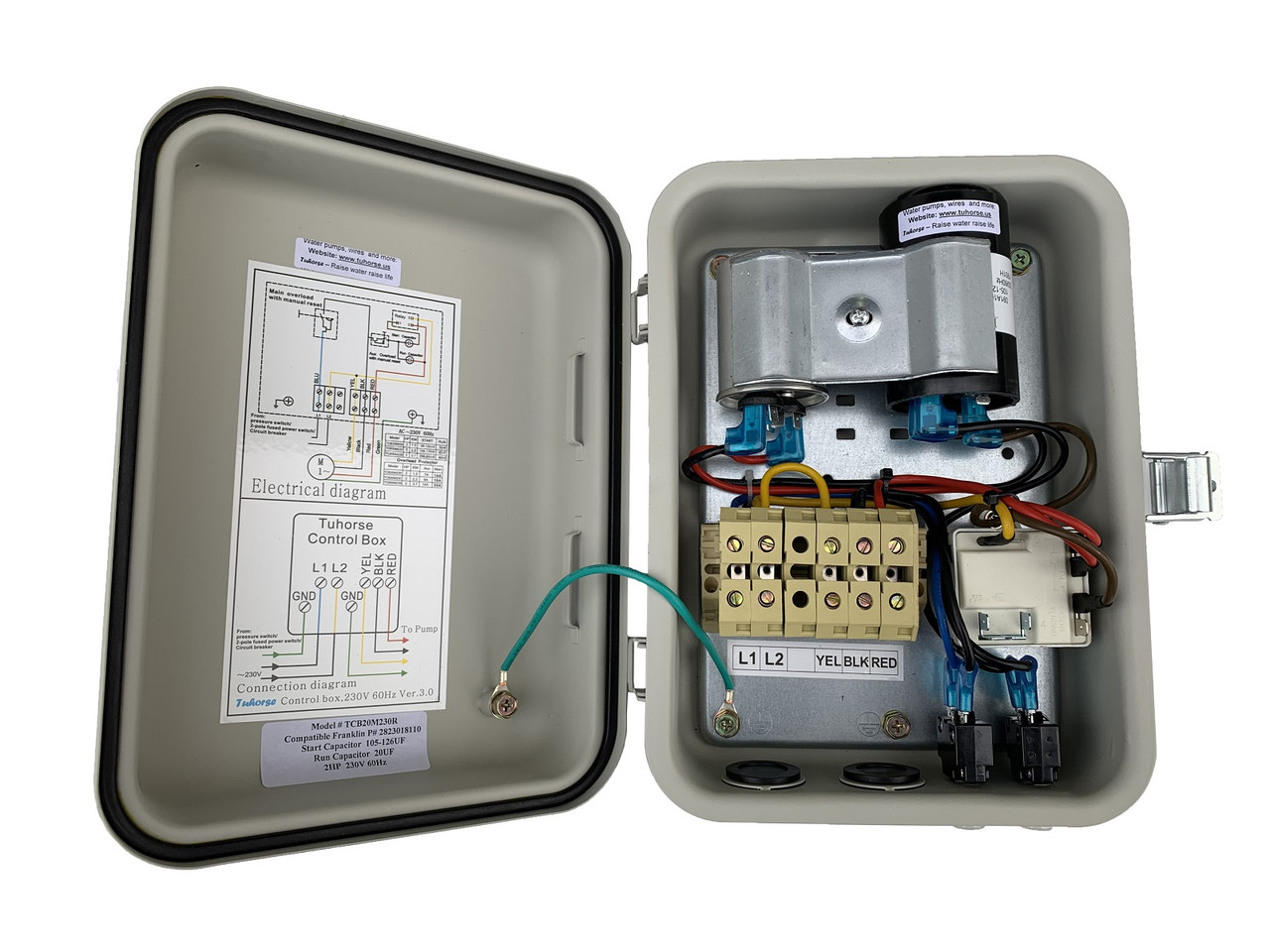
2HP Control Box. Compatible Replacement for Franklin 2823018110 and Goulds CB20412CR

Franklin QD Control Box | 1 HP - 230V
900 wiring diagram.cdr

Well pump troubleshooting - DoItYourself.com Community Forums
Installation and Operation Manual

How to Test the Relay in Franklin Electric Control Boxes
Flow-Thru Expansion Tanks

franklin electric motor wiring diagram Questions & Answers ...
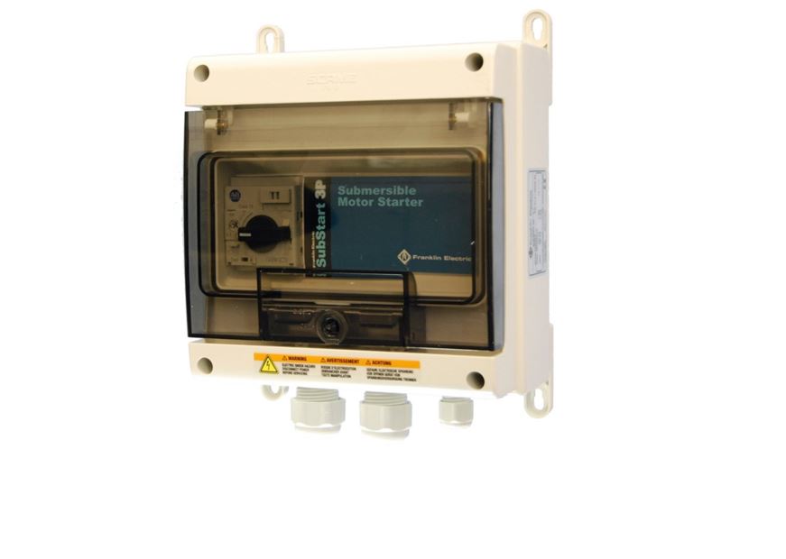
Franklin Electric E-tech Substart3P Three Phase Motor Starter
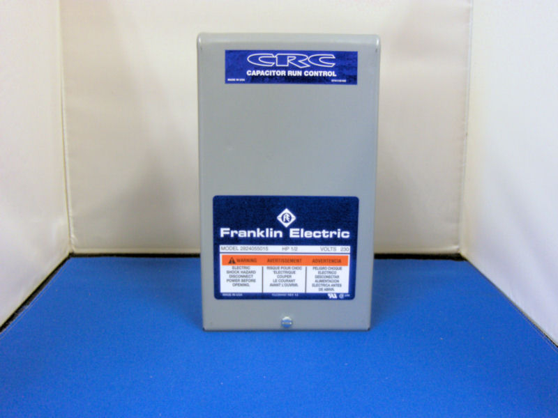
Franklin 1HP 230V CRC Control Box
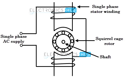
Types of Single Phase Induction Motors
Franklin Electric 2822019310 Deluxe Submersible Motor Control Box 7.5 HP 230V 1PH For 3-Wire Motors

AIM Manual - Page 57 | Single-Phase Motors and Controls ...
Water Pump Wiring Troubleshooting & Repair Pump Wiring Diagrams
Texas 5 HP Motor for Sale | B&M Pump Irrigation Sales ...
Franklin 15HP 230V Deluxe Control Box
wiring franklin inst-o-verse motor | DIY Home Improvement Forum
Backup power for a community well - Energy - Syonyk's ...
Pumptec trickle system help | Terry Love Plumbing Advice ...
How to Wire a Franklin Electric QD Control Box (1/3-1 HP)
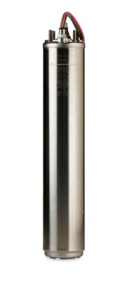
Franklin Electric S.A. - Encapsulated Submersible Motors
Franklin electric explosion proof motor 1111007456 3/4
Spa Pump $114.95 Free Freight Factory Direct Why Pay Retail ...

AIM Manual - Page 57 | Single-Phase Motors and Controls ...
Level Control Panel 1 Single Phase 2-wire 0.37kw to 2.2kw

Intelligent Pump Soft-Starter - Franklin Electric

Franklin Electric 2823028310 - 3 HP - Submersible Motor Control Box - DELUXE w/ Magnetic Contactor

Franklin Electric enhances VFD
Deep Well Submersible Pump Motor: 15 HP, 3,450 Nameplate RPM, 460V AC, 3 Wires

Electric pump motor wiring - Home Improvement Stack Exchange
Franklin electric explosion proof motor 1111007456 3/4

AIM Manual - Page 56 | Single-Phase Motors and Controls ...
0 Response to "40 franklin electric motor wiring diagram"
Post a Comment