37 Fuel Oil Piping Diagram
An Engineering Guide to Modern Fuel Systems requirements of modern diesel fuel or fuel oil systems. ... head pressure caused by piping layout or pressure drop through the cooler must be.28 pages Fuel oils Fuel oil pipes and drain pipes Fuel oil pipe insulation Fuel oil pipe heat tracing Components for fuel oil system. An automatic vent slide allows circulation of fuel oil through the valve and high pressure pipes when the engine is stopped.
Fuel Oil Piping Systems Installation Instructions | Manualzz OPW FlexWorks Fuel Oil Piping Systems are designed to provide a reliable, secondarily contained, underground fuel supply system to generators and boilers from remote fuel tanks. Typical applications include a 3/4" or 1" supply and a 1" overflow return line running from a remote AST or UST to a...
Fuel oil piping diagram
Section 231113 - facility fuel-oil piping FACILITY FUEL-OIL PIPING 231113 - 6 Copyright 2013 AIA MasterSpec Premium PRODUCT MASTERSPEC LICENSED BY ARCOM TO OMEGAFLEX, INC. h. 2. 3. 4. 5. 6. 7. 8. B. Listed and labeled for aboveground and underground applications by an NRTL acceptable to authorities having... Fuel Oil System for Marine Diesel Engine Marine Fuel oil system includes various piping systems provided for bunkering, storage, transfer, offloading and treatment of fuel oils. Fuel oil transfer system - This system receives and stores fuel and delivers it to settling tanks. Fuel oils are loaded through deck fill connections that have sample... SUPERVISE FUEL-OIL PIPING AND STORAGE IN BUILDINGS Fuel-Oil Piping and Storage System (P 98- W98). Date of Test: Written tests are ... refer to DIAGRAM #1 on the following page. The oil storage tank provides ...21 pages
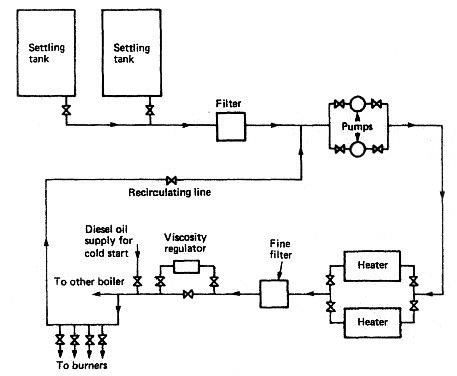
Fuel oil piping diagram. Fuel oil - Wikipedia Fuel oil (also known as heavy oil, marine fuel, bunker, furnace oil, or gasoil) is a fraction obtained from the distillation of petroleum (crude oil). It includes distillates (the lighter fractions) and residues (the heavier fractions). PDF PowerPoint Presentation The diagram below shows a Fuel oil supply system for a large 2 stroke crosshead engine. However the set up is typical of any fuel system for a marine diesel engine operating on 2. Following the same diagram above describe the fuel oil system and the passage of fuel oil from the DB tank to the engine. Fuel Oil Piping | PDF | Pipe (Fluid Conveyance) | Valve 1. Division 2 Section "Fuel-Oil Distribution" for fuel oil storage tanks, fuel oil piping, specialties, and accessories outside the building. 2. Division 15 Section "Basic Mechanical Materials and Methods" for flexible connectors. 3. Division 15 Section "Hangers and Supports" for pipe supports... 31 Fuel Oil Piping Diagram - Wiring Diagram Database Fuel oil piping diagram. Inspection for above ground heating oil storage tanks asts. Piping Diagram Ship Wiring Schematic Diagram 20 Laiser. Figure 2 11 Lubricating Oil System Piping Diagram. In Line Leak Testing Procedure For Checking Skotch Trifecta Oil.
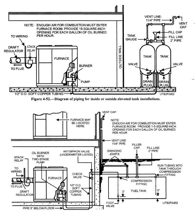
Two Line Fuel Unit "Heating Oil Pump" Unit Piping Hookups Oil burner fuel unit installation & maintenance guide: this article describes the function, diagnosis, adjustment, and repair of oil burner fuel units or "oil pumps", and we provide related oil burner fuel unit safety, heating system efficiency and heating cost savings advice. Fuel oil piping layout - HVAC/R engineering - Eng-Tips 23 Sept 2005 — Hi, what's a good reference (online or off) for boiler fuel oil piping layout. Mainly I need to know when it's ok to use only burner mounted ...7 posts · The need for a recirculation loop (or not) would be burner specific, depending upon whether ... Standard Piping Diagram - Veterans Affairs BURNER FUEL OIL SYSTEMS - STANDARD PIPING DIAGRAM. FOS. 0-1500kPa. [0-200 PSIG]. FUEL FLOW CONTROL to foto. VALVE. 0–1.5xMAX. BURNER 4 4 0-1.5XMAX. BURNER.1 page Oil Pipes - Pressure Loss vs. Oil Flow Oil pipe pressure drops in pounds per square inch (psi) per 100 ft pipe are indicated in the diagrams below. Fuels - Viscosities vs. Temperature - Fuels oil viscosities vs. temperature. ISO Grade Oils - Viscosities and Densities - Viscosities and densities of ISO - and equivalent SAE grade oils.
How to Read Oil and Gas P&ID Symbols | Kimray P&ID (Piping and Instrumentation Diagram) vs PFD (Process Flow Diagram). Process diagrams can be broken down into two major categories: process Here are the symbols for pumps, tanks, and other types of equipment. The most common pumps used in oil and gas industry are screw, progressive... PDF Fuel-oil piping and storage system. Supervise fuel-oil piping and storage in buildings. Consolidated Examination for the Certificate of Fitness for City Wide Fuel-Oil Piping and Storage System (P 98- W98). Date of Test: Written tests are conducted Monday to Friday (except legal holidays) 9:00 AM to 2:30 PM. Fuel Oil Piping Diagrams Convert Details: Fuel Oil Transfer Pump Piping Diagram amp manufacturer megator. marine gas diesel jp 8 fuel bladder tanks and fuelockers. heat pump Fuel-Oil Piping and Storage, NYC Mechanical How To Draw a Piping & Instrumentation Diagram (P&ID) Fuel Performance Calculations Miles per Gallon... PDF Oilon 4_EN 260112.indd diagram for heavy fuel oil Gas pressure control assembly. Oilon oil, gas, and dual fuel burners are fully automatic, safe, and. Capacity regulation methods. They are also designed to suit furnaces with high back pressure. Oil piping Mounted on the burner, three-stage burners with four solenoid.
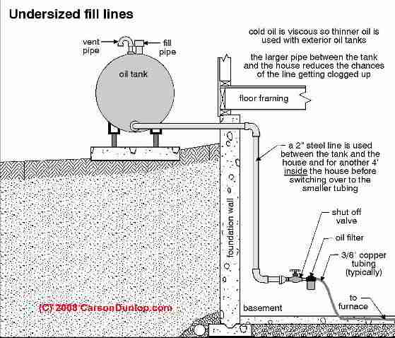
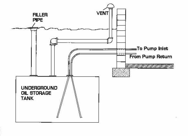
Oil Tank Fill & Vent Piping Installation & Inspection
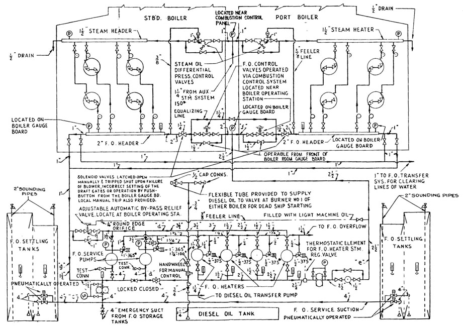
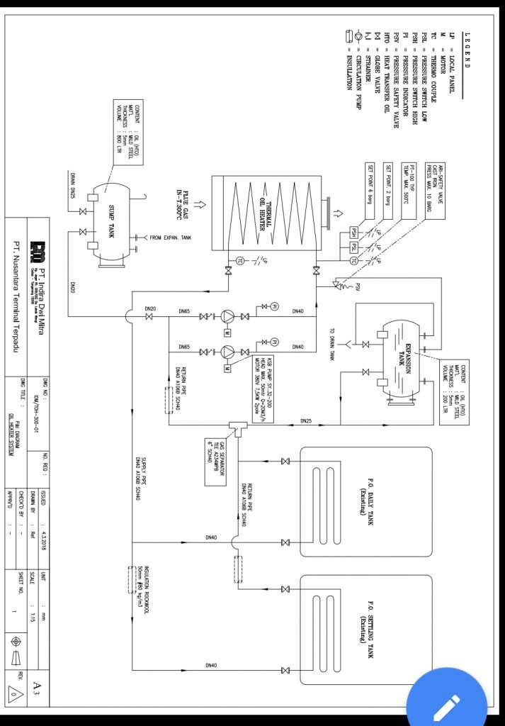
Figure 2-9. Fuel oil system piping diagram. (5) Secure the fuel oil system (para 2-12). piping connects directly to the propulsion engine, the Figure 2-9. Fuel oil system piping diagram.
Apakah solar menguap di kolom pencampuran selama pergantian ...
PDF Installation, operation and maintenance MANUAL | OIL FIRED BOILERS Fuel oil piping. Connect Oil Lines To Boiler 1. Use flexible oil lines so the burner swing door can be. Oil piping must be abso-lutely air tight or leaks or loss of prime may result. Bleed line and fuel unit completely. Refer to your local jurisdic-tions regarding any special considerations for fuel supply...
Sistem Pengisian Bahan Bakar
PDF Wärtsilä 20 Product Guide | 6. Fuel Oil System 6. Fuel Oil System. 6.1 Acceptable fuel characteristics. 6.1.1 Marine Diesel Fuel (MDF). If minimum smoke during load increase is a major priority, slower loading rate than in the diagram can be Fuel, lubricating oil, fresh water and compressed air piping is usually made in seamless carbon steel (DIN...
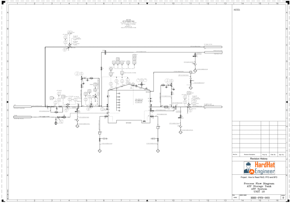
Learn How to Read P&ID Drawings - A Complete Guide
PDF Microsoft Word - Lecture 6 Fuel System | S.No Name of fuel oil PROPERTIES OF FUEL Fuel is a substance consumed by the engine to produce energy. The important properties of these fuels are given below: S.No Name of fuel oil. (i) Fuel tank (ii) Fuel filter (iii) Sediment bowl (iv) Fuel lift pump (v) Carburettor (vi) Fuel pipes (vii) Inlet manifold.
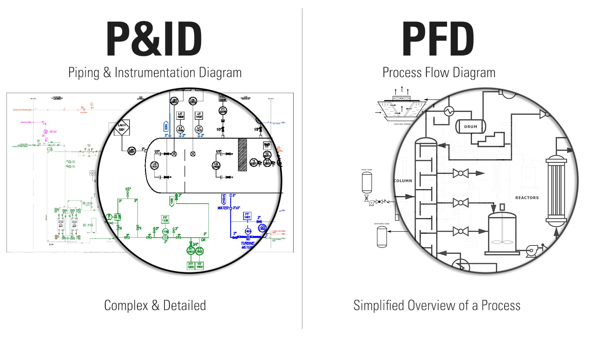
How to Read Oil and Gas P&ID Symbols | Kimray
PDF K80MC-C Mk 6 Project Guide | Specific fuel oil consumption (SFOC) insulation Fuel oil pipes, steam & jacket water heating Fuel oil heating chart Fuel oil supply unit Fuel oil system Fuel oil venting box. Gallery arrangement Gallery outline GenSets, Holeby Governors Guide force moments. Heat radiation Heated drain box with fuel oil leakage alarm Heating of drain pipes...

Fuel Oil Day Tanks - BEC Equipment, LLC | Boiler Service ...
FUEL OIL PIPING AND STORAGE SECTION 1301. GENERAL. 1301.1 Scope. This chapter shall govern the design, installa- tion, construction and repair of fuel-oil storage and piping systems.4 pages
TSPS Engineering Manual
PDF Microsoft Word - 22 50 00 Fuel Oil Piping (012914) A. Fuel Oil Piping Buried Below Ground: 1. Pipe: Provide ASTM A53, Grade B, Seamless or ERW, Schedule 40 carbon steel or glass fiber reinforced epoxy piping ASTM D2992, filament wound, reinforced, thermosetting epoxy resin piping with threaded and bonded fittings and connections.

Dual-Fuel Engines | DAIHATSU DIESEL
PDF Fuel oil and insurance claims Fuel oil causes, or contributes, to many serious insurance claims. Examples: Damaged cylinder liners After taking on bunkers in a European port, a ship's The bunker plan is a piping (schematic) diagram that is accurate and representative of the bunkering system onboard. The plan should show the...
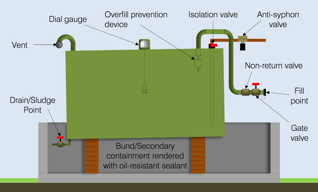
Get to Know Your Oil Storage Tank
PDF Project Guide - Marine | Fuel Oil System The built-on fuel oil system consists of inlet pipes for fuel oil, mechanical fuel pump units, high-pressure pipes as well as return pipes for fuel oil. Fuel Oil Diagram. From centrifuges. Diesel oil cooler.

Fire pump Storage tank Diesel fuel Piping and instrumentation ...
PDF DNVGL-RU-SHIP-Pt4Ch6 Piping systems Fuel oil system. S010 - Piping diagram (PD). Fresh water system. — pump and filter housings in fuel and lubrication oil systems where the design temperature does not exceed 120°C. 1.4.3 Grey cast iron may be used for class III piping, with the following exceptions

Pyrolysis process piping and instrumentation diagram ...
PDF FOREWORD | 3. Cooling Water, Lubricating Oil and Fuel Oil | Forum 16 High pressure fuel pipe clamping type. Purpose of use. Measures engine RPM's using pulse system, irrelevantly to the center of the rotary shaft (1) Piston cooling nozzle function A nozzle made of a steel pipe is installed below the main gallery in the cylinder body. The lubricating oil from the...
Heating Oil Tank & Piping Sludge Prevention or Cures Oil ...
Guideline for Oil transfer system on board ship Before commencing fuel oil transfer operation, chief engineer shall post a line diagram of the vessel's oil transfer piping including the location of each Cargo piping - tankers: Cargo piping in tankers is usually mild steel and is protected from rusting by external painting. Most large oil tankers have the...
Boiler Efficiency and Combustion Control
PDF Subject - Properties of fuel oil to be considered - Inspection items by flag States and port State control Addendum A - Flow diagrams - Cleaning of cargo tanks and disposal of tank washings/ballast 1.3.19 Independent means that a piping or venting system, for example, is in no way connected to...
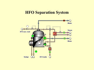
FUEL SYSTEM TANKER (HEAVY FUEL OIL SYSTEM)| IDMBoiler
PDF Guide for Vessels Operating in Low Temperature Environments For fuel oil filling pipes located on the deck, alternative arrangements to protect the filling pipes are to be provided. 5.3.2. Cooling System. • Details of the arrangements for the use of cargo as fuel and associated fuel gas piping diagrams and other arrangements for utilization of boil-off gas (BOG).

Dual-Fuel Engines | DAIHATSU DIESEL
PDF C Manual Oil supply piping. The C burner is designed for use with light grade fuel oils - commercial standard grades #2 or #1. It is recommended that prior to installation If your system uses other than a COMBU pump, refer to the oil piping diagram and oil pump manufacturer's bulletin supplied with the burner...
Conventional Fuel Oil System Flow line. | Download Scientific ...
SUPERVISE FUEL-OIL PIPING AND STORAGE IN BUILDINGS Fuel-Oil Piping and Storage System (P 98- W98). Date of Test: Written tests are ... refer to DIAGRAM #1 on the following page. The oil storage tank provides ...21 pages
Buildings Bulletins 2018-010 - Technical
Fuel Oil System for Marine Diesel Engine Marine Fuel oil system includes various piping systems provided for bunkering, storage, transfer, offloading and treatment of fuel oils. Fuel oil transfer system - This system receives and stores fuel and delivers it to settling tanks. Fuel oils are loaded through deck fill connections that have sample...
Maintenance of Fuel Oil Systems
Section 231113 - facility fuel-oil piping FACILITY FUEL-OIL PIPING 231113 - 6 Copyright 2013 AIA MasterSpec Premium PRODUCT MASTERSPEC LICENSED BY ARCOM TO OMEGAFLEX, INC. h. 2. 3. 4. 5. 6. 7. 8. B. Listed and labeled for aboveground and underground applications by an NRTL acceptable to authorities having...
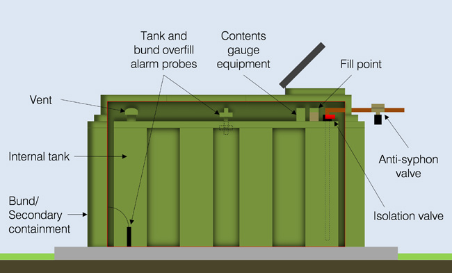
Get to Know Your Oil Storage Tank

The Risks of Purchasing Property with an Abandoned ...

BOILER FUEL OIL SYSTEM
Various Design Burners for Marine Boiler

Oil refinery - Wikipedia, the free encyclopedia | Oil ...

Marine Sea Time: FUEL OIL LINE DIAGRAM AND EXPLANATION IN SHIP
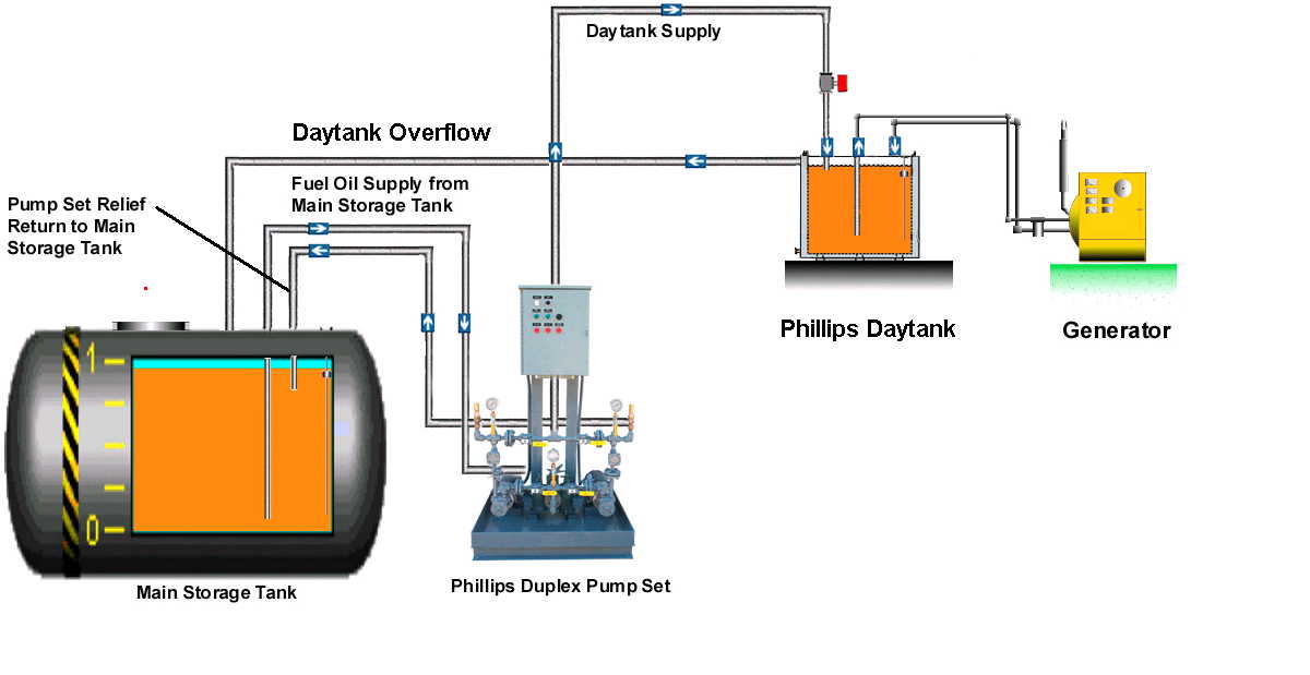
Phillips Pump: Guide Specification for Generator Daytank ...

How to Draw and Read Line Diagrams Onboard Ships?
Marine piping systems
SUPERVISE FUEL-OIL PIPING AND STORAGE IN BUILDINGS

Investigating Fuel Oil Leaks and Spills – Expert Article ...

Oil And Gas Piping Training Guide - powerfultx's diary

Siklus Bahan Bakar Minyak pada PLTU

Open vented system with an oil boiler and a solid fuel stove ...

Single and Double Fuel Tank Piping Diagram — Heating Help ...
RB-EG-UE410 Preparation of PFD and EFD/P&ID
![FAQ] Guidance for 2020 Fuel Switch - mfame.guru](https://mfame.guru/wp-content/uploads/2019/12/Fuel-oil-piping.jpg)
FAQ] Guidance for 2020 Fuel Switch - mfame.guru

DG & ME FUEL OIL SYSTEM DIAGRAM

Investigating Fuel Oil Leaks and Spills – Expert Article ...
0 Response to "37 Fuel Oil Piping Diagram"
Post a Comment