42 pressure sensor circuit diagram
Texas Instruments has been making progress possible for decades. We are a global semiconductor company that designs, manufactures, tests and sells analog and embedded processing chips. 08/01/2012 · Any electrical signal processing always requires a voltage supply (an “active part”) and a “load”, such as a pressure sensor, which represents the “passive part”. Sometimes the active part of the interconnection is also described as a power source/voltage source and the passive part is referred to as a “current sink”. In order that an electrical circuit can function, …
A circuit diagram of the GY-BMP280-3.3 pressure sensor module can be seen below. BMP280 Module Application Enhancement of GPS navigation (e.g. time-to-first-fix improvement, dead-reckoning, slope detection) Indoor navigation (floor detection, elevator detection) Outdoor navigation, leisure and sports applications

Pressure sensor circuit diagram
September 7, 2020 - General purpose differential amplifier project has been designed for various pressure sensor amplifier applications. Circuit provided... Learn the best practices to install and use a pressure transducer is in this article. Understand the concepts before installing your sensor. Pressure Detector Circuits and Block Diagram Basics · Electronics, Instrumentation & Electrical Database Sensors and Transducers Suppiers Menu
Pressure sensor circuit diagram. The code P0236 sets when the PCM detects a signal from the boost pressure sensor that does not meet the expected values. The boost pressure sensor tells the PCM how much boost is created by the turbocharger. Note: The definition of code P0236 may be different depending on the vehicle manufacturer. Consult the appropriate repair manual or repair ... How it works. The basic principle, when a human or warm-blooded animal comes to a radius of about 3 to 5 meters. This circuit detects infrared radiation from theirs and sends an alarm. See the circuit diagram below. When a signal from an Infrared PIR Sensor module comes to the circuit. It is a 3V peak voltage. Oil Pressure Sensor Switch Help Wiring Page 2 Honda Tech Forum Discussion. Part Number 30 5135 Analog Style 150 Psi Oil Pressure Gauge. 3 Wire Oil Pressure Sensor Wiring Diagram S 10 Forum. Aem 30 4407 Digital Oil Pressure Gauge Instructions Manualzz. Agricultural Machinery Sel Engine Oil Pressure Sensor 2 Wire Switch. Avnet is a global leader of electronic components and services, guiding makers and manufacturers from design to delivery. Let Avnet help you reach further.
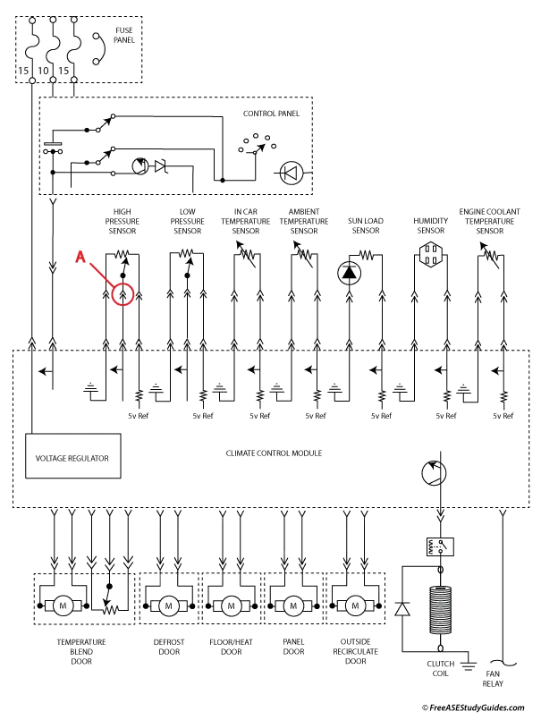
A24 Pressure Sensor Wiring Diagram Map Sensor Sensor Car Maintenance. 3 Wire Oil Pressure Switch Www Sassycleanersmd Com. 3 2 Oil Pressure Sensor Fault P0520 Alfa Romeo Forum. Mitsubishi Oil Pressure Sending Unit Wiring Diagram Wiring Diagram 171 Back. Gm Pressure Sensor Wiring Pose Research Wiring Diagram Library Pose Research Kivitour It. The Vapor Pressure Sensor (VPS) measures the vapor pressure in the evaporative emission control system. The Vapor Pressure Sensor may be located on the fuel tank, near the charcoal canister assembly, or in a remote location. This sensor uses a silicon chip with a calibrated reference pressure on one side of the chip, the other side of the chip ... Figures of cross-section morphology of the MTP pressure sensor, dimension and photograph of the printing paper with the interdigitated electrodes, photographs of the tissue paper and MTP, equivalent circuit diagram of the MTP pressure sensor, XPS measurments of MXene powder, SEM image of tissue paper, sheet resistance of the MTP sheet prepared ... A pressure sensor will have a given voltage at a certain pressure. If the sensor passes this test, perform the same test at the computer using the wiring diagram to locate the pressure sensor signal wire pin. If the voltage is not the same at the computer as it was at the sensor, repair the wire.
Board mount pressure sensors, as the name implies, are pressure sensors designed to be mounted on a PCB (Printed Circuit Board), thus becoming an integrated part of an electronic assembly. While some sensors are designed to evaluate the physical contact pressure between a sensor and a solid object, others are specifically intended to measure ... Various pressure sensors on break-out boards can be purchased from vendors such as Adafruit [1], SparkFun [3] and others for literally just a few dollars. Most break-out boards, such as the MPL115A2 I²C Barometric Pressure/Temperature Sensor Board in Figure 3 are available with I 2 C interface and can be readily used with platforms such as ... Making a "Pigtail" to Connect to MegaSquirt. You will need to connect your MegaSquirt ® EFI controller to power, ground, sensors, fuel pump, fast idle valve, and injectors. You can do this using 18 or 20 gauge wires. The ground and injector wires carry more current, however they are "doubled-up" on the board. 30/10/2020 · Pressure Sensor Circuit Diagram. By Margaret Byrd | October 30, 2020. 0 Comment. Pressure sensor circuit without using diagram of alarm schematic simplified electrical electronic sensors the design engineer connectdetect simple amplifier over transducer. Pressure Sensor Circuit Without Using Microcontroller Gadgetronicx Circuit Diagram Of …

electrical circuit diagram of eot crane ~ Circuit Diagrams
December 1, 2021 - Reading hydraulic and pneumatic circuit diagrams and making sense out of them is a valuable skill for mill personnel, starting with fluid control elements.
Flexiforce Pressure Sensor (25lbs) Quick Start Guide ...
Connecting Heart Rate sensor and BME280 sensor. The MAX30100 is an integrated pulse oximetry and heart-rate monitor sensor solution. It combines two LEDs, a photodetector, optimized optics, and low-noise analog signal processing to detect pulse oximetry and heart-rate signals.
Fuel Tank Pressure Sensor Problems and Check Engine Lights
Bridge-sensor circuit diagram Piezo resistive pressure sensor operating principle The piezo electric effect can be exploited in multiple ways to sense pressure CONSTANT CURRENT RESOURCE (-1.5mA) +VEXC +VEXC/GND RTZ RTS SIGNAL-SIGNAL+ AMPLIFIED OUTPUT ZERO TRIM RESISTORS Doped piezoresistor SIDE VIEW Piezoresistive sensors Tensile …

| Repair Guides | Fuel Injected Electronic Engine Controls ...
The sensor can be defined as a device which can be used to sense/detect the physical quantity like force, pressure, strain, light etc and then convert it into desired output like the electrical signal to measure the applied physical quantity. In few cases, a sensor alone may not be sufficient to analyze the obtained signal.
Pressure Sensor BMP180 Arduino Circuit Diagram
The BMP180 sensor will measure the Atmospheric Pressure. The DHT11 sensor will measure the temperature and humidity of the climate. ... Make connections according to the circuit diagram and add virtual terminals to Serial pins to see the readings and Data.

Yellow Porsche 911
Easily Master 3 4 Pin Map Sensor Wiring Diagram In 2 Min. Dtc P0107 How To Test Your Ls1 Map Sensor. Map Sensor Replacing 0261230030 0261230174 46553045. Micro Introduction. 1996 1998 Map Sensor Circuit Diagram 1 6l Civic. 1996 1998 Map Sensor Circuit Diagram 2 0l Neon.

air suspension compressor unplug – MB Medic
Pressure Sensor & Wiring DiagramAmazon Printed Bookshttps://www.createspace.com/3623928Amazon Kindle Editionhttp://www.amazon.com/Automotive-Electronic-Diagn...
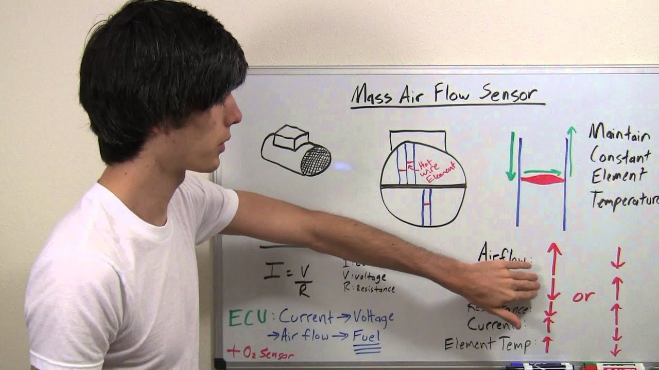
Mass Air Flow Sensor - Hot Wire - Explained - YouTube
This bulletin applies to BMW 2, 3, 4 and 5 series vehicles produced to December 20, 2014, with the N20 and N26 engines. The Service Engine Soon (MIL) light may be on with DTC 195002 (differential pressure sensor, tank vent valve, electrical short circuit to ground) stored. During engine operation, vibration and movement of the sensor can damage the pin contacts of the harness connector or ...

Schematic Diagram of E 3 S 3 F-I (Static pressure sensor ...
Wika Pressure Transmitter A 10 Wiring Diagram. Druktransmitter a 10 wika benelux stock germany pressure sensor transmitter xi an ao xin automation instrument co ltd integration of sensors into the plc blog difference 4 20 ma in 2 wire 3 technology oem o rsinstruments model name number rsigp 1007 rs 1950 piece id 21334722891 12725057 ...
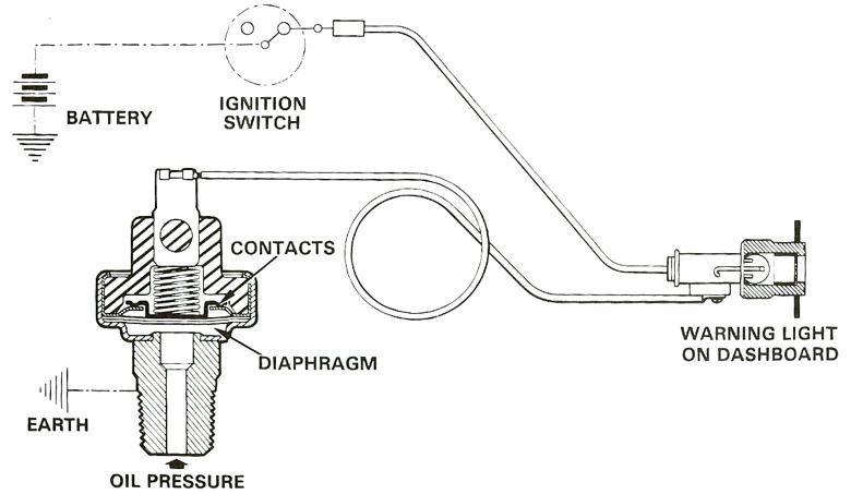
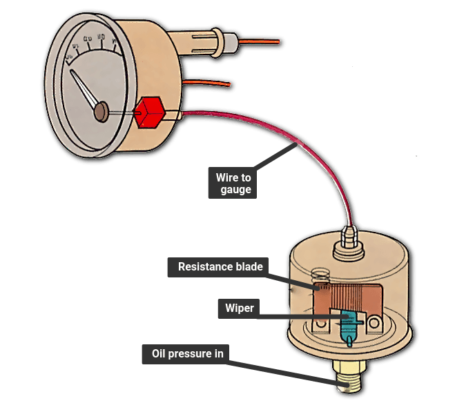
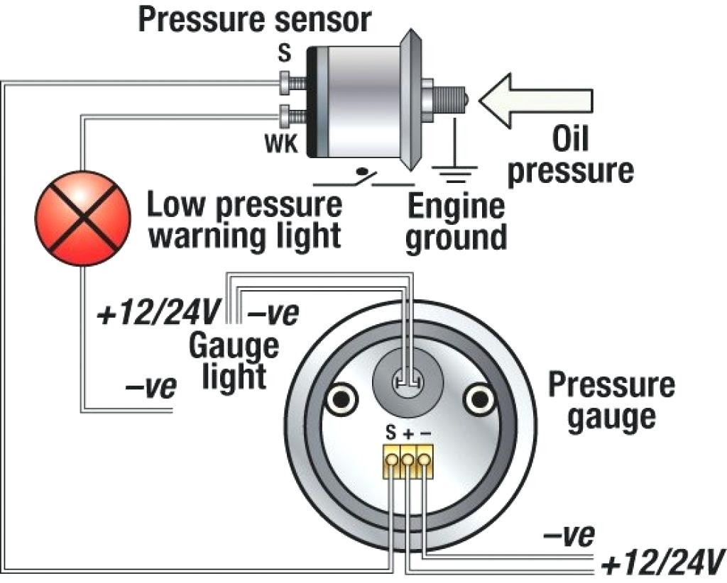
Low Oil Pressure Warning Switch - Wiring Diagram - Tech ...
The Aluminum End Cap with 18 Holes comes with five blank penetrators, one Bar30 Pressure Sensor, one Enclosure Vent and Plug, and two power cables preinstalled. Use the Bulkhead Wrench to remove the two blank penetrators marked below from the end cap and set them aside, they will be used in the next step.

P0935 – Hydraulic Pressure Sensor Circuit High ...
27/03/2018 · Also see the GY-BMP280-3.3 pressure sensor module pinout for pin numbering and circuit diagram of the module pictured below. GY-BMP280-3.3 Pressure Sensor Module. This tutorial shows first use and testing of the GY-BMP280-3.3 pressure sensor module so that you will know whether the device is working or not. The video below shows an Arduino Due …

Circuit Diagram of Pressure Sensor | Download Scientific ...
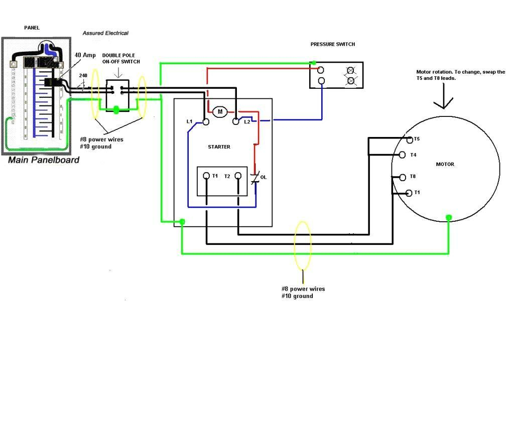
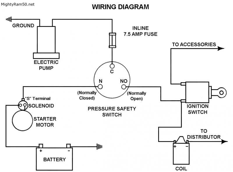
A pressure switch is a device that operates an electrical contact when a preset fluid pressure is reached. The switch makes an electrical contact on either pressure rise or pressure fall from a certain preset pressure level.
Danfoss Pressure Switch Wiring Diagram
This conversion process can be done with the strain gage’s physical deformation that is connected into the pressure transducer’s diaphragm & wired in the design of a Wheatstone bridge. Once the pressure is applied to this transducer, then it generates the diaphragm deflection. The strain will generate the change of an electrical resistance which is proportional …

Vdo Oil Pressure Gauge Wiring Diagram
The simple circuit diagram can be seen below: In this configuration, the hall effect sensor will convert a magnetic field within a specified proximity and will convert it into a linear analogue signal across its "out" pin. This analogue signal can be easily used for driving a load or for feeding any desired switching circuit.
Electronic pressure switch circuit diagram - Basic_Circuit ...
November 1, 2021 - This article describes three example hydraulic schematic diagrams: cylinder movement, sizer applicator beam turning and pope reel secondary arm movement.
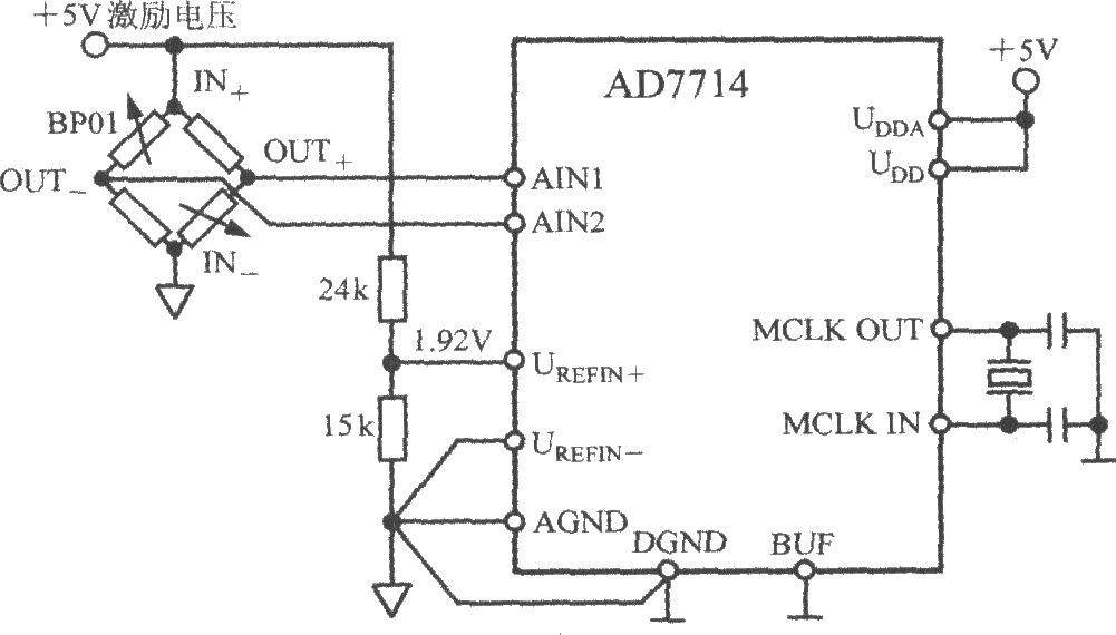
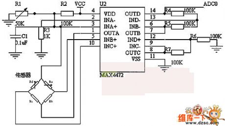
The pressure measurement system circuit using 5 - channel ...
The output voltage of the pressure sensors is read using a multimeter. The results of both pressure sensors are plotted on a graph of the pressure versus output ...
Air Compressor Pressure Switch Wiring Diagram - Cadician's ...
10/10/2010 · Whenever, the pressure sensor element (Piezo-ceramic wafer) is gently tapped, mosfet T1 is fired by the electric pulse from the sensor through related components and IC1 is again enabled by T1. As a result, the piezo-sounder starts beeping for a short duration, set by the in-circuit values of R3 and C2. Piezo-sounder at the output of IC1 can be replaced with a low …
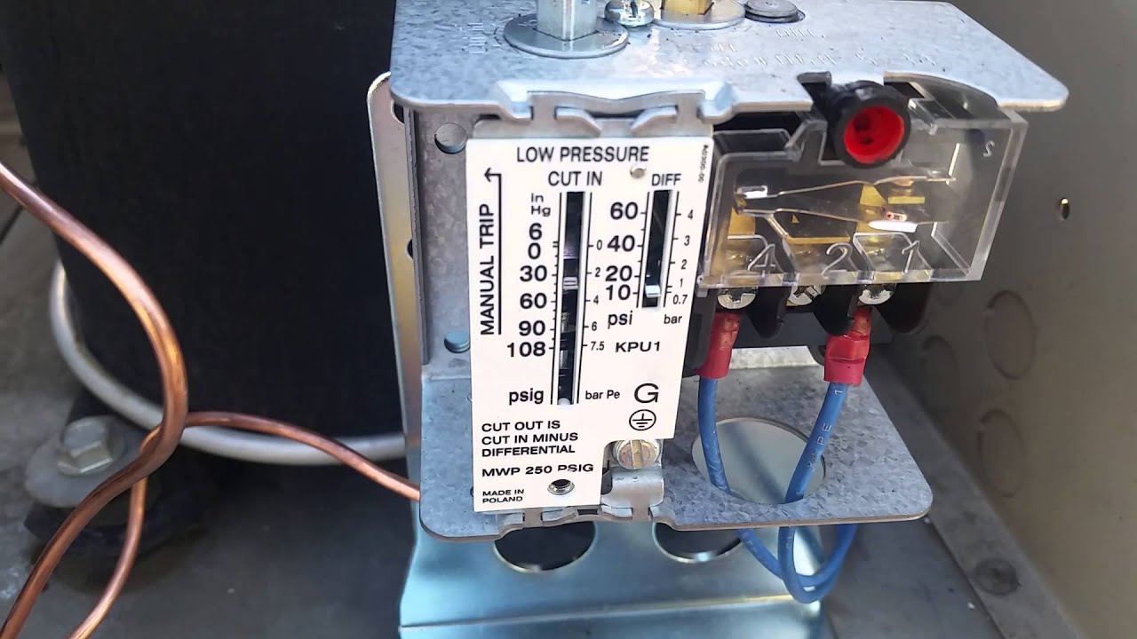
pressure switch label | Electrical Academia
Diagnostic trouble code (DTC) P0191 stands for "Fuel Rail Pressure Sensor Circuit "A" Range/Performance." It indicates a potential abnormality in the fuel rail pressure readings. Because of either a mechanical or electrical problem, the signal sent by the fuel rail pressure sensor doesn't match the value the PCM expects to see.

2015 Odyssey - P0848 - Transmission Fluid Pressure Sensor ...
TE connectors and sensors are embedded in almost every type of device, where reliable and persistent data, power, sensing, and connectivity are required — even in the harshest environments.
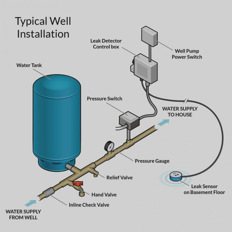
Well Pump Pressure Switch Wiring Diagram | Wiring Diagram
Analog Devices is a global leader in the design and manufacturing of analog, mixed signal, and DSP integrated circuits to help solve the toughest engineering challenges.
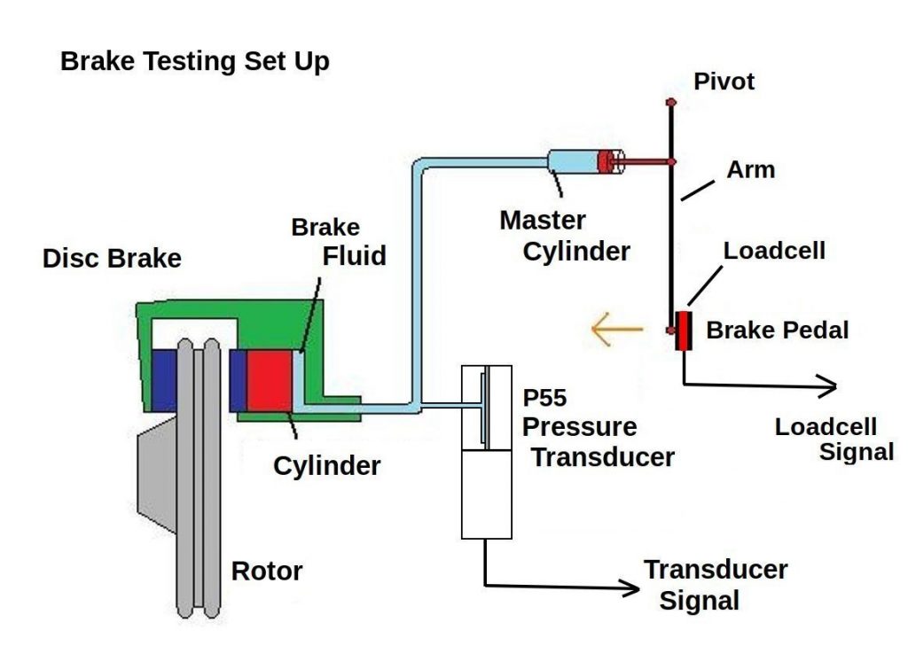
automatic braking systems Archives | Validyne Engineering
July 29, 2021 - The circuit shown in Figure 1 is a robust and flexible loop-powered current transmitter that converts the differential voltage output from a pressure sensor to a 4 mA-to-20 mA current output.The design is optimized for a wide variety of bridge based voltage or current driven pressure sensors, ...
Push Button Switch Types and Circuit Diagram
The BMP 180 sensor is the high accurate digital pressure sensor of the BMPX series. Which is use for both academic and commercial purposes. It is use to measure atmospheric pressure or barometric pressure. Barometric pressure or atmospheric pressure is the pressure exerted by the weight of the air above you.

Water Pump Pressure Switch Wiring Diagram - Database ...
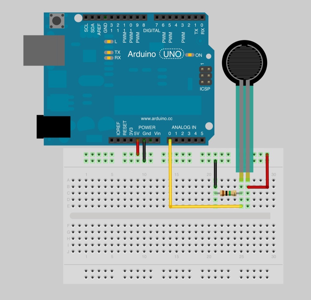
If you're applying a quite a bit of pressure to the FSR so that the resistance drops to 50,000 ohms our equation will be (100,000 / (100,000 + 50,000)) * 5 = ~3.3 volts. This should read about 700 on the analog pin. Circuit Diagram As I mentioned above, the circuit diagram for a force sensing resistor is really straight forward with the Arduino.

How a Pressure Switch Works ~ Learning Instrumentation And ...
Code P0190 Definition. Fuel Rail Pressure Sensor - Circuit Malfunction. What does the P0190 code mean? The P0190 trouble code means that there is an issue in the circuit between the engine control unit and the fuel rail pressure sensor.. The fuel rail pressure sensor's function is to measure the fuel pressure in the fuel rail and then report it to the engine control unit.

Square D Air Compressor Pressure Switch Wiring Diagram ...
Circuit diagrams and Schematic designs, Electronics, Sensor Circuits. IC, op amp, opamp. In this Pressure sensor circuit we are going to use Piezo element as sensor. Because we need to obtain an electric signal from a mechanic signal or force. You might have seen circuits where digital output switches states depends on threshold pressure.
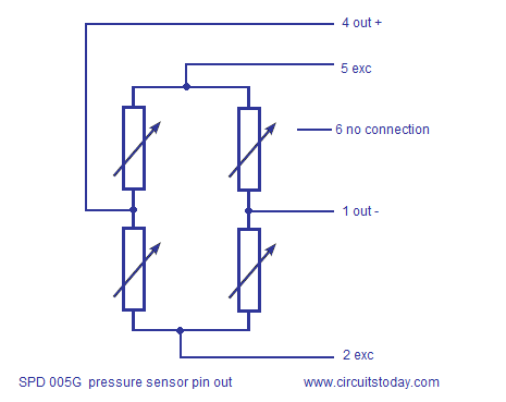
Interfacing SPD005G Pressure Sensor To Arduino-Circuit ...
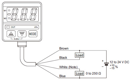
2 wire pressure transmitter wiring diagram. A 2 wire transmitter has only 2 wires and is connected in series with the power supply and the plc. It reveals the parts of the circuit as streamlined shapes and the power as well as signal connections in between the gadgets.

3 Wire Pressure Transducer Wiring Diagram Sample
PSD25 Wiring Diagrams Cable Assembly Wiring Colors: Pin 1 - Brown Pin 2 - White Pin 3 - Blue Pin 4 - Black Note: wiring colors are based on AutomationDirect CD12L and CD12M 4-pole PNP cable assemblies. PSD25 Series Pressure Switches See our website www.AutomationDirect.com for complete Engineering drawings. tPRS-2 Pressure Sensors and Gauges 1 ...
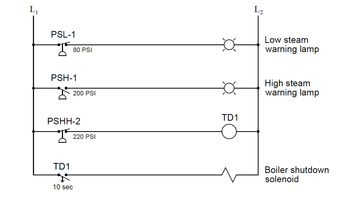
Determine the functions of Pressure Switches ...
November 29, 2019 - Any book or lesson in fluid power worth its weight in gold will discuss the importance of electrical and electronic control of hydraulics. In fact, over

Water Well Pressure Switch Wiring Diagram - Wiring Diagram ...
It is simple and inexpensive circuit because it has small geometry and simple pressure sensor. It just uses a single Operational Amplifier. This circuit obtain power from from 3-V battery. To work properly this circuit must work in 0 C to 50 C temperature range. Here is the schematic diagram : This ...
High Pressure Sensor Circuit Question and Answer
Light Sensor Circuit Working Operation. The light sensor circuit is an electronic circuit designed using (light sensor) LDR, Darlington pair, relay, diode, and resistors which are connected as shown in the light sensor circuit diagram. A 230v AC supply is provided to the load (in this case, the load is represented with a lamp).

Pressure Switch Schematic Circuit Diagram
August 14, 2017 - Interfacing pressure sensor to arduino. SPD005G is the pressure sensor used here. The sensor output is amplified and displayed on LCD screen
Pressure Sensor Wiring Diagram - Wiring Diagram
A simple signal conditioning circuit should allow the output of the amplifier to be independent of the sensor used, providing interchangeability and high ...5 pages

4 20ma Pressure Transducer Wiring Diagram Sample
Access 130+ million publications and connect with 20+ million researchers. Join for free and gain visibility by uploading your research.
Pressure Sensor - Sensor Circuit - Circuit Diagram ...
Pressure Switch Schematic Circuit Diagram. Admin July 3, 2018. 0 65 1 minute read. A simple pressure switch with a range of 50 to 350 bar can be made using a pressure sensor. If you can accept somewhat reduced linearity, the sensor can even be used up to 500 bar. As shown in the schematic diagram, the circuit contains very few components other ...
Changed Oil Pressure Switch... now Engine Sounds Terrible ...
Raspberry Pi here collects the Humidity and temperature data from DHT11 and atmospheric pressure from BMP180 sensor and then sends it to 16x2 LCD and ThingSpeak server. ThingSpeak displays the Data in form of Graph as below: You can learn more about DHT11 Sensor and its Interfacing with Arduino here. Circuit Diagram:

Pressure Sensor & Wiring Diagram - YouTube
Circuit Diagram For ESP8266 & BME280 IoT Weather Station. Now, Let's wire the BME280 sensor with the NodeMCU ESP8266. The Connections are fairly simple. Start by connecting the VIN pin to the 3.3V output on the NodeMCU and connect GND to the Ground Pin. We use now the remaining SCL and SDA pins for I2C communication.
Micro-differential Pressure High-precision Digital ...
Pressure Transmitter For General Applications Model A 10. 8643652 wika s 10 general purpose 11 pressure transmitter operating instructions manual transmitters electronic product catalog pdf free lesman sensor membrane is 3 analog psd 30 for a lh tronic reference 9 2009 indd ut sanitary with dpt china universal mbs 3000 type f 20 specs manualzz ipt metallic measurement diaphragm 4 3a ls ...
Glowshift Oil Pressure Gauge Wiring
October 1, 2020 - This method is used, where we cannot ... high temperature or pressure zones, etc. The ultrasonic sensor-based distance measurement project circuit kit is shown in the figure. The distance measurement by the ultrasonic sensor project circuit block diagram is shown in the block diagram ...

Circuit Diagram of Quarter-bridge Strain Gauge Pressure ...
Below is the circuit diagram or connection for IoT Based Air Pollution/Quality Monitoring System. There are 3 sensors which is connected to wifi chip NodeMCU ESP8266 12E. PMS5003 Sensor works on UART Communication. It has 8 pins and counting is done from the right.

Pressure Transmitter Circuit - InstrumentationTools
The compressor provides the system pressure for raising the vehicle as well as a pressure relief valve for lowering it. The compressor relay is responsible for starting and stopping the compressor. Mercedes-Benz CLS-Class & E-Class Compressor, Relay/Fuse Location. The compressor is located in the forward portion of the front-left wheel well.

a: temperature sensor with signal conditioning circuit; b ...
When the ignition SW is turned on and the brake pedal is pressed (Stop lamp SW on), if the stop light circuit is open, the current flowing from TERMINAL 7 of the light failure sensor to TERMINALS 1, 2 changes, so the light failure sensor detects the disconnection and the warning circuit of the light failure sensor is activated.
3 Wire Pressure Sensor Circuit Diagram - Wiring Diagram ...
An absolute pressure sensor may be designed to respond to pressure applied at the top side or the back side, when mounted on a circuit board or a panel, for example. Creating a port for the measured media to enter through the top side may leave the sensor vulnerable to hazards such as physical damage or contamination with dirt or moisture. A bottom-side entry sensor may be …
0 Response to "42 pressure sensor circuit diagram"
Post a Comment