40 4-20ma pressure transducer wiring diagram
The current loop in a 4-20mA system has less impedance and due to this, the noise immunity of the signal is high when compared to a voltage-driven system. What are the different types of 4-20mA wiring arrangements? Loop powered(2 wire) In this type of arrangement, the sensor would be usually a two-wired device. Wiring Schematic. 4. Cable Wiring. Standard & Conduit w/ Cable. 5. Submersible Cable Wire ... temperature of the pressure transducer is -40°C to 92°C.
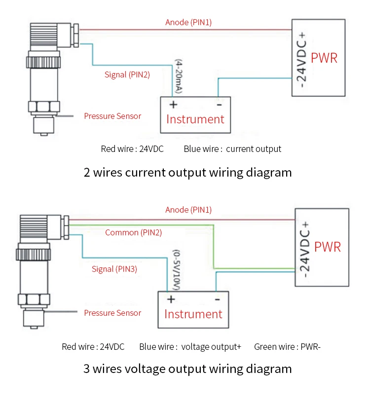
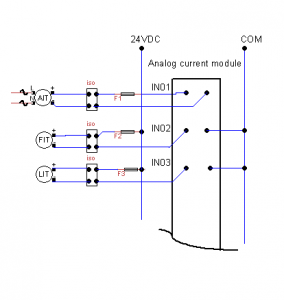
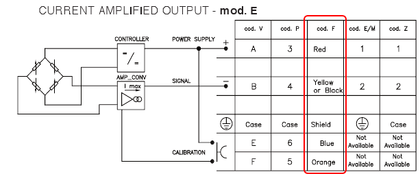
Typical wiring configuration for current output transducer Figure 4. Multi-instrument 4-20mA current loop (panel meters, chart recorder, computers, etc.) Minimum voltage req'd = (0.20 Amps) (R LINE + R LOAD) + Vs TRANSDUCER Figure 5. Multiple instruments wired in parallel to a voltage output transducer
4-20ma pressure transducer wiring diagram
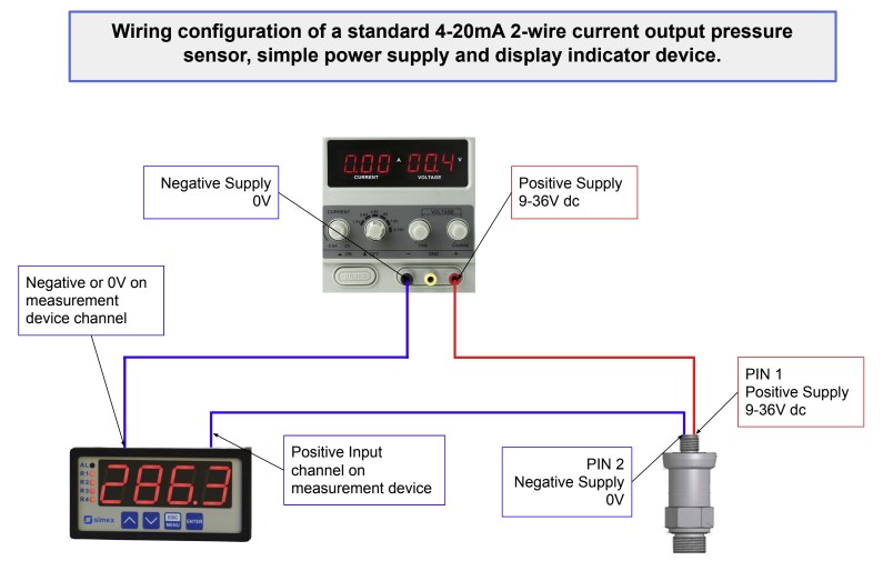
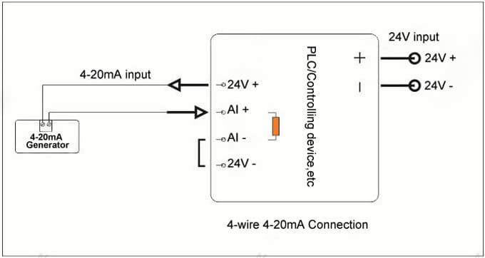
A) If the 4-20mA Input Device includes an Internal Sensor Power Supply and has 2 input connections: Connect Positive (+) Input connection to Positive (+) Pressure Transmitter connection; Connect Negative (-) Input connection to Negative (-) Pressure Transmitter connection; B) If the 4-20mA Input Device requires an External Sensor Power Supply and has 2 input connections: A wiring diagram is a streamlined standard pictorial depiction of an electric circuit. 2 wire pressure transducer wiring diagram 4 20ma transmitter circuit diagram awesome 3 wire pressure transducer wiring diagram. All devices in a 4 20 ma current loop need to be supplied power from somewhere in order to function. While reviewing the wiring diagram on some pressure transmitters (2-wire 4-20mA output, direct wire) I'm about to buy I noticed a slight inconsistency with the wiring in the NI9203 user manual. Here are links to the user manuals for the sensors: Swagelok pressure transducers
4-20ma pressure transducer wiring diagram. Pressure sensor link, https://www.ato.com/pressure-sensorThe video shows the connection of the 2-wire ATO pressure sensor/transducer. The ATO pressure sensor... 4-20mA Wiring Schematic. How To Guide. For this how to guide, there are three components; power supply, Core Sensors pressure transducer, and a meter or ... Reference Manual 00809-0100-4007, Rev BC July 2020 Rosemount™ 3051 Pressure Transmitter with 4-20 mA HART® Revision 5 and 7 Selectable Protocol 4-20mA (2 wire loop powered)* +Temp -Press +Press -Temp NOTICE FOR HAZARDOUS AREA SENSORS (AST46PT) - Refer to operating instructions for installation information. * For units with loop-powered 4-20mA output, the pressure loop must be powered or the temperature output will not operate.
Get 4 20ma Pressure Transducer Wiring Diagram Sample. Assortment of 4 20ma pressure transducer wiring diagram. A wiring diagram is a streamlined standard photographic depiction of an electrical circuit. It shows the elements of the circuit as streamlined shapes, as well as the power and signal connections in between the gadgets. Industrial transmitters are available for monitoring many parameters these including pressure, temperature and flow etc. Gas detectors / transmitters offer 4-20mA outputs, where 4 mA equates to a zero reading and 20 mA equates a full scale reading of the calibrated range.. This signal is sent to a remotely located control panel. 3 wire pressure transducer wiring diagram - 4 20ma Pressure Transducer Wiring Diagram Elegant Viatran Model Rm570 Br Pressure Transmitter. File Type: JPG. Source: kmestc.com. Variety of 3 wire pressure transducer wiring diagram. Click on the image to enlarge, and then save it to your computer by right clicking on the image. The SI-300 4-20mA/Voltage Pressure Transducer, also called pressure transmitter 4-20mA. It is a pressure sensor with 4-20ma/Voltage output. 4-20mA Pressure Transducer can be OEM as differential pressure, explosion-proof, or sanitary, just as you need.Ideal for OEMs, process applications, water processing, and industrial pressure applications.
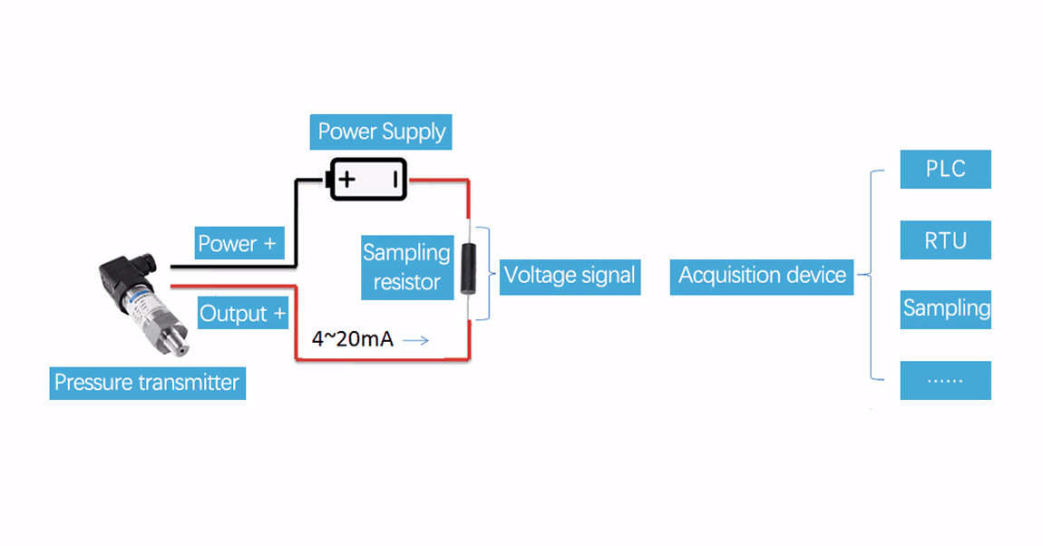
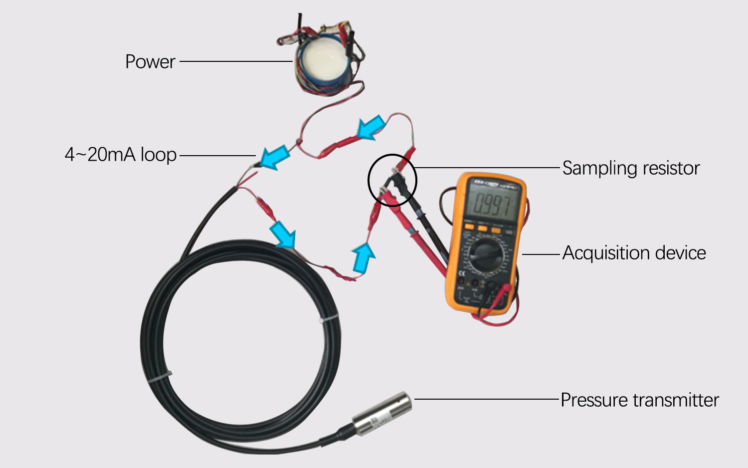
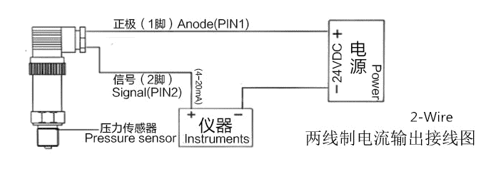
May 26, 2020 · Collection of 4 20ma pressure transducer wiring diagram. A wiring diagram is a streamlined traditional photographic depiction of an electric circuit. It shows the parts of the circuit as simplified shapes, and also the power and signal connections in between the gadgets. Figure 1. It is a typical usage of two-wire 4-20mA pressure transmitters for most customers showed in figure 1. After the pressure transmitter is powered on, the loop current is proportional to the pressure to generate a 4-20 mA signal by collecting the pressure. The current flow through the sampling resistor (typical 100 Ω, 250 Ω) which ... 3 Wire. Pressure transducers installation and low voltage 20 bar range oem water 4 20ma transmitter wiring circuit diffeial transducer schematic diagram to connect sensors into the plc small pump control loop or 0 5 meter fuel oil hydraulic 2 5vdc connection electrical connections guide 600 sensor wire 3 danfoss mbs 3000 output for air change 93a e pcs1 indd vs d105 connecting how it gems ... As shown in the diagram above, current supplied from the power supply flows through the loop wires with resistance, RW, to the transmitter and the 4 - 20mA transmitter regulates the current flow within the loop. The current allowed by the transmitter is called the loop current and it is proportional to the parameter that is being measured.
Common Troubleshooting for 2-wire 4-20ma Pressure ...
converters (current-to-pressure transducers) are available to convert the 4-20mA control loops to common pneumatic ranges, such as 3-15psi, 1-18psi, 3-27psi, and 6-30psi. In two-wire 4-20mA control loops, we use 2-wire transmitters to convert various process signals representing flow, speed, position, level, temperature,

Convert 4-20ma current output to foundation fieldbus ...
NaK FILLED MELT PRESSURE. TRANSMITTERS. SERIE KE. 4...20mA output. The KE Series are for use in high temperature applica-.

Pressure Transmitter 4-20mA With 1.5" Flush Diaphragm Seal ...
4 20ma pressure transducer wiring diagram – What is a Wiring Diagram? A wiring diagram is an easy visual representation from the physical connections and physical layout of the electrical system or circuit.

Example 4-20mA thermistor transmitter wiring diagram ...
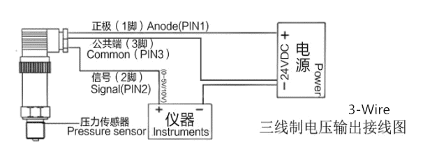
Today's electronic process transmitters - pressure, temperature, flow and level are connected in different wire types or configurations. These connection methods are of great concern to the instrument engineer/technician. The 2 - Wire, 3 - Wire and 4 - Wire types are often used to describe the method of connection of electronic transmitters.

Perspective sur la nef centrale de la basilique-cathédrale Saint-Gervais-et-Saint-Protais C’est une cathédrale catholique romaine de style gothique classique. Elle a été érigée en basilique mineure le 10 mars 1857. La construction de l'actuelle cathédrale de Soissons, la troisième dans l'histoire, commence en 1176 et se poursuit durant trois siècles. La célébration de la dédicace par l'évêque Jean Milet a lieu le 25 avril 1479.
WIRING DIAGRAM FOR MODEL CXLdp MODEL CXLdp DIFFERENTIAL PRESSURE TRANSDUCER (4-20mA) INSTALLATION & MAINTENANCE SHEET ZERO SPAN Zero adjust potentiometer Span adjust To troubleshoot or verify performance, it is recommended to pneumatically connect the pressure ports to each other and establish a zero offset reading in the as-installed position.

4 20ma Wiring Diagram - Fuse & Wiring Diagram
A typical 4-20mA current loop setup contains 3 things power supply — Most of the devices work at 24V DC but there are other voltage standards available as well4-20mA current loop sensor — this is the device which works as 4-20mA standard. for example, it could be a temperature sensor which gives the temperature value in the form of 4-20mA4 ...

4 20ma Pressure Transducer Wiring Diagram | Free Wiring ...
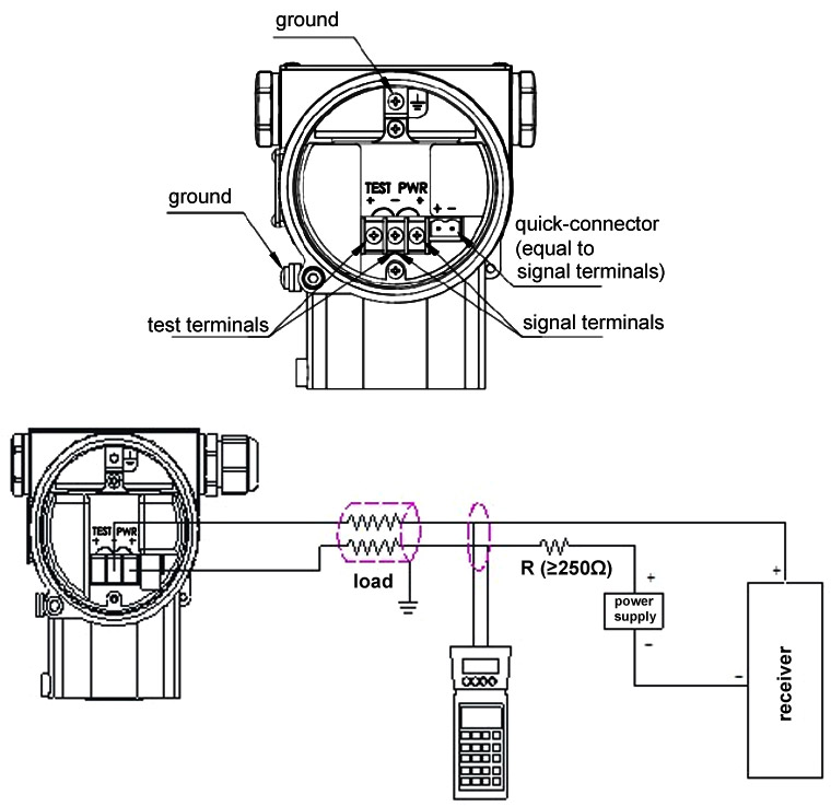
Also most (and yours according to the second datasheet) 4-20ma transmitters utilize only use two wires to the sensor, labled + & -. You have to create a current loop comprising of a voltage source (10V to 30V d.c. (24V d.c. maximum above 110°C)) and a 250 ohm resistor. The wiring would go from negative of the voltage source to resistor, then ...

How a Current to Pressure Transducer (I/P) Works ...
Mar 18, 2018 · 4 20ma Pressure Transducer Wiring Diagram Download. 4 20ma pressure transducer wiring diagram - A Novice s Overview of Circuit Diagrams An initial appearance at a circuit representation could be complicated, but if you can read a subway map, you could check out schematics. The function is the exact same: receiving from point A to direct B.…

Pressure Transmitter Pressure Transducer 4-20ma | Kaidi
The 4-20 mA current loop is the dominant standard in many industries. It is the simplest option to connect and configure. It uses less wiring and connections than other signals, greatly reducing initial setup costs. Better for traveling long distances, as current does not degrade over long connections like voltage.
4 20ma Circuit Diagram - Wiring Diagram Networks
Pressure transmitter a 10 wika stock germany sensor xi an ao xin automation instrument co ltd 12725057 automation24 difference of 4 20 ma in 2 wire 3 technology blog 8341155 s general purpose valin c10 0 5000 psi 1 npt 20ma 8347390 sanitary with flush face diaphragm thermosense direct jiangsu huahai m c hh316 display user manual n… Read More »
2 Wires 4-20ma 0-10v Refrigeration Air Compressor Air ...
Pressure sensors with a 0.5…4.5V output for industrial 3-wires current loop (4…20mA) applications Nov. 2004 4/9 Analog-Digital Micromechanical Sensor Systems Description of the application Pressure transmitter SM5812's output signal of 0.5V…4.5V is to be converted into an output current signal of 4…20mA as a 3-wire version.

Ashcroft Pressure Transducer Wiring Diagram | Free Wiring ...
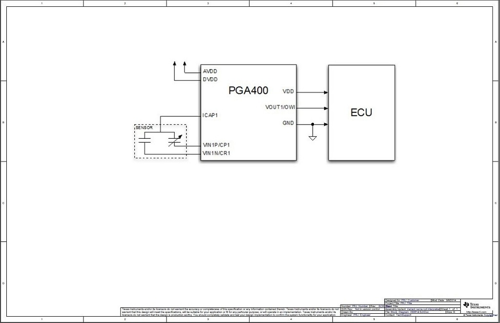
The circuit is commonly used in 2-wire field sensor-transmitters such as Flow Transmitters, Level Transmitters, Pressure Transmitters, and Temperature Transmitters. Design Notes 1. Select a single channel DAC with the required resolution and accuracy for the application. ... 4-20mA current output, 100uA supply current, SPI, 2.7V to 3.3V supply

5 to 1600PSI Pressure Transducer Sensor Output 0.5-4.5V 4 ...
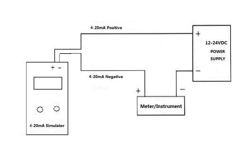
4-20mA Help 2 wire 4-20ma pressure transmitter wiring configuration. The diagram below below shows a simple wiring configuration for current loop pressure transmitter. It is assumed that the measurement device includes a sufficient load resistance for measuring a current loop.
4 20ma Circuit Diagram - Wiring Diagram Networks
Jun 27, 2018 · Pwm Controlled 4 20 Ma Cur Loop Transmitter Provides Galvanic Isolation Edn. Small circuit forms programmable 4 to how a 20 ma transmitter works 20ma diagram t5 pressure signal conditioner max1459 loop powered transmitters sensors measure in cur sensor interface cn0314 note analog devices tester temperature op90 with the max12900 prefer signals 2 wire pwm controlled conversion science of loops ...
Number 4 in a building’s stairwell
0...10Vdc (3 wires) / 4...20mA (2 wires) ... KH transmitters are based on film sensing element deposited ... ELECTRICAL CONNECTION - Connection diagrams.5 pages
Pressure Transducer Wiring Diagram - PURPLE-ITU-UNGGU
While reviewing the wiring diagram on some pressure transmitters (2-wire 4-20mA output, direct wire) I'm about to buy I noticed a slight inconsistency with the wiring in the NI9203 user manual. Here are links to the user manuals for the sensors: Swagelok pressure transducers
Common Troubleshooting for 2-wire 4-20ma Pressure ...
A wiring diagram is a streamlined standard pictorial depiction of an electric circuit. 2 wire pressure transducer wiring diagram 4 20ma transmitter circuit diagram awesome 3 wire pressure transducer wiring diagram. All devices in a 4 20 ma current loop need to be supplied power from somewhere in order to function.

4 Wire Pressure Transducer Wiring Diagram - Drivenheisenberg
A) If the 4-20mA Input Device includes an Internal Sensor Power Supply and has 2 input connections: Connect Positive (+) Input connection to Positive (+) Pressure Transmitter connection; Connect Negative (-) Input connection to Negative (-) Pressure Transmitter connection; B) If the 4-20mA Input Device requires an External Sensor Power Supply and has 2 input connections:
Pressure Transducer|Transmitter 4-20mA/Voltage-Sino-Instrument
4-20ma signal generator circuit diagram - Gallery 4K

Pressure Transducers | Pressure Transmitters | Pressure ...

4 20ma Pressure Transducer Wiring Diagram Sample

¿Amamos al prójimo como a nosotros mismos?
Differential Pressure Transducer, Output 4-20mA HART | ATO.com

Automatic Control: 4 20Ma circuit schematic
How to read and troubleshoot analog 4-20mA loop devices ...
4 20Ma Pressure Transducer Wiring Diagram Database

4 20ma Circuit Diagram - Wiring Diagram Networks

4 20ma Circuit Diagram - Wiring Diagram Networks

three people praying at shrine (2)

4 20ma Circuit Diagram - Wiring Diagram Networks
TPHADA Ultra High Range Pressure Sensor - SensorsONE

4 20ma Circuit Diagram - Wiring Diagram Networks
Pressure Transducer|Transmitter 4-20mA/Voltage-Sino-Instrument

4 20ma Wiring Diagram - Wiring Diagram Networks

AA Wiring

3 Wire Pressure Transducer Wiring Diagram Sample

4 20ma Pressure Transducer Wiring Diagram | Free Wiring ...

4 20ma Wiring Diagram - Fuse & Wiring Diagram
Plc To Lvdt Wiring Diagram - Wiring Diagram
0 Response to "40 4-20ma pressure transducer wiring diagram"
Post a Comment