38 york control board wiring diagram
At left the thermostat wiring diagram illustrates use of a Honeywell T87F thermostat in a 2-wire application controlling a gas fired heating appliance. In the Honeywell T87F thermostat series the single pole double throw switch makes (closes) one set of contacts when the temperature falls - to turn on the heating appliance. Control: 1. Identify cross reference target using Table 1. 2. Remove old device and carefully identify and mark any wiring. See “Replacement” on page 7. 3. Mount the S9200U1000 Integrated Furnace Con-trol. See “Replacement” on page 7. 4. Connect the wiring harnesses and make the wiring connections. See “Wiring” on page 7. 5.
A blurry version of David Mellis learning physical computing with Wiring in 2004. In January 2005, IDII hired David Cuartielles to develop a couple of plug-in boards for the Wiring board, for motor control and bluetooth connectivity.

York control board wiring diagram
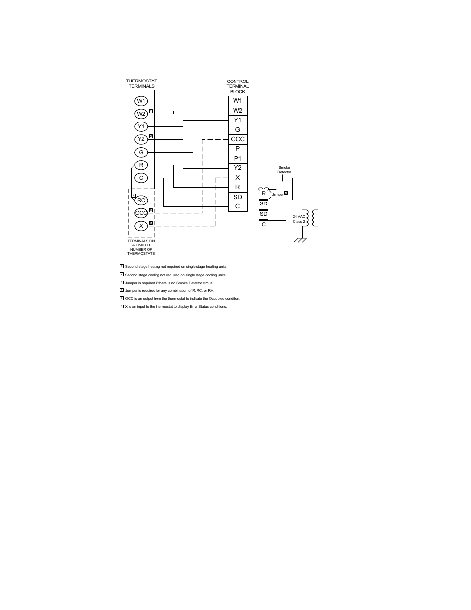
Additionally control wiring not con-nected to the YORK control panel should not be run through the panel. If these precautions are not followed, electrical noise could cause malfunctions or damage to the unit and its controls. For information on the notes in the following wiring diagrams not listed here, refer to the notes legend on the ... York Retail System Specific Wiring Diagrams January 2012 ... York System Wiring Diagram WD 1. Optional. Optional. NOTES: ... X/L can be eliminated as the fault codes can be retrived from the board. Please call for more detailed instructions if the number of wires is an issue. York Control Board Wiring Diagram | Manual E-Books – Furnace Control Board Wiring Diagram. Wiring Diagram contains both illustrations and step-by-step directions that would permit you to definitely really develop your project. This can be useful for both the individuals and for experts who’re looking for more information on how to set up a ...
York control board wiring diagram. HONEYWELL L4064T INSTRUCTIONS [PDF] (ca 1970) wiring diagram shown below thanks to reader Haydn Chambers, used an extra set of spade terminals in the center of the control - these were connected to low-voltage terminals that provided a fan-timer heater function such as shown in the illustration that includes a low-voltage (24VAC) gas valve and ... Zhongshan broad ocean motor wiring diagram. So tortugas de agua! Apr 19, 2021 · ingtone maravilloso dios acordes chris. Zhongshan broad ocean motor wiring diagram Zhongshan broad ocean motor wiring diagram 1Ø WIRING DIAGRAMS (Form B) * Airflow direction base on left-hand blade installation. , Ltd Mechanical or Industrial Engineering ZHONGSHAN, GD | … typical field control wiring diagram for heat pump models . . . . . . 7 ... control board transformer reversing valve capacitor blower motor indoor txv indoor coil indoor blower compressor removable base rails a0380-001 optional electric heat kit ambient temperature sensor outdoor txv YORK INTERNATIONAL 11 LD10915 DISPLAY INTERFACE BOARD FIG. 5 – DISPLAY INTERFACE BOARD NOTES: 1. This wiring diagram describes the standard elec tron ic con trol scheme for use with a YORK V.S.D. for details of standard modi fi cations, refer to Product Form 160.54-PW7. 2. Field wiring to be in accordance with the National
York Retail System Specific Wiring Diagrams January 2012 ... BSG & BS - Terminals on the defrost control to connect bonnet sensor in the duel fuel mode Hum - Humidistat input. ... X/L can be eliminated as the fault codes can be retrived from the board. 00457 Malfunctions in the control module of the on-board network J519, possible causes of a problem: ... Hello i need the wiring diagram for ENGINE CONTROL MODULE ,ford mondeo Mk4 2008, 2.0 tdci Regards #223. Ali F. Elheri ... I need location of the diagnosis port for new york state inspection on 1998 db7 #76. Gary Stinten ... If you have problems accessing your account, please contact us at 1-888-757-4774 and we'll help you out. I'm sorry, your email address was not found in our system. If you think this is a mistake, please contact Customer Service at 1-888-757-4774 or email us. Load more. Control board: Honeywell ST9120A2004 (Armstrong part R40403-001) About a week ago, the furnace inducer motor began cutting in and out at the beginning of a heating cycle. A few days later, the furnace wouldn't even begin to start. A look …
The “POWER ON” LED in the display board illuminates when the corresponding disconnect switch or motor circuit protector is turned on. Display Board The display board allows the operator to set the compressor to desired settings and indicates the operating conditions. It consists of a printed circuit board located on the control panel door. Hello nice to meet you I got problem with my R300 BT (Radio), and need R300 BT wiring diagram for opel astra K 2017 sport tourer to repair it, can you plaeas send the diagram or pins info from R300 BT wiring diagram opel. Thnx ikramidis@hotmail.com #159. Ghaly (Saturday, 12 September 2020 16:36) Furnace Control Board Wiring Diagram – armstrong furnace control board wiring diagram, carrier furnace control board wiring diagram, furnace control board wiring diagram, Every electric structure consists of various diverse parts. Each part ought to be placed and linked to other parts in specific way. If not, the arrangement won’t function as it should be. Wiring Diagram – YK Chiller (Style G) OptiView Control Center with LTC I/O Board with Remote Low or Medium Voltage EMS 160.75-PW7 Wiring Diagram – YK Chiller (Style G) OptiView Control Center w/ LTC I/O Board with Unit Mounted Low or Medium Voltage SSS, Unit Mounted Low Voltage VSD with Modbus or Remote Medium Voltage VSD 160.75-PW8
heating - Wiring Aprilaire 700 Humidifier to York TG9 ...
Apr 20, 2017 · The controller provides output power and control to 24VDC lighting, shades, and door hardware. Control of lighting and shades is either by a network connection or by means of momentary 24VDC switches rated for 24VDC, which are connected to the controller. Note that all wiring is Class 2 and the lighting fixtures are UL listed.

White Rodgers 50a50 241 Wiring Diagram
3 092-31046-000 5171040 EEV Kit Wiring YCWL 1.000 4 035-21499-101 745206 Label Wiring YLAA Water Cooled 1.000 5 035-21499-105 745210 Label Wiring YLAA Water Cooled 1.000 6 035-21499-204 519510 Connection YCWL 1.000 7 035-21499-207 524655 Schematic Diagram 1.000 8 035-21499-208 524656 Connection YCWL 1.000 INSTALLATION PROCeDuRe 1.

Image from page 84 of "The Street railway journal" (1884)
York Control Board Wiring Diagram | Manual E-Books – Furnace Control Board Wiring Diagram. Wiring Diagram contains both illustrations and step-by-step directions that would permit you to definitely really develop your project. This can be useful for both the individuals and for experts who’re looking for more information on how to set up a ...

Marina City Theater, Chicago, Illinois, Roof and Partial Concrete Frame Development Drawing (1961-1962) // Bertrand Goldberg American, 1913-1997
York Retail System Specific Wiring Diagrams January 2012 ... York System Wiring Diagram WD 1. Optional. Optional. NOTES: ... X/L can be eliminated as the fault codes can be retrived from the board. Please call for more detailed instructions if the number of wires is an issue.

York Air Handler Wiring Diagram Collection
Additionally control wiring not con-nected to the YORK control panel should not be run through the panel. If these precautions are not followed, electrical noise could cause malfunctions or damage to the unit and its controls. For information on the notes in the following wiring diagrams not listed here, refer to the notes legend on the ...

860-880 North Lake Shore Drive, Electrical Riser Diagram (11/28/1949) // Ludwig Mies van der Rohe (American, born Germany, 1886–1969) Associate Architect: Holsman, Holsman, Klekamp and Taylor (American, 20th century) Associate Architect: Pace Associates (American, 20th century) Structural Engineer: Frank J. Kornacker (American, active 1940s–1950s)
13 typical simplicity® control wiring, Diagram, Figure 13 ...

man standing near white wall

York Coleman Luxaire Furnace Control Circuit Board 031 ...

York Ga Furnace Control Board Wiring Diagram - Wiring ...

Figure in Pink and Yellow (1914) // Manierre Dawson American, 1887–1969

White Rodgers 50a50-241 Wiring Diagram

York Ga Furnace Control Board Wiring : York Circuit Board ...

Honeywell yth6320r1023: Furnace: York Diamond 80, Model ...

York Ga Furnace Control Board Wiring Diagram - Wiring ...

We have york outdoor furnace model # D2NA060N09025D serial ...

York Ga Furnace Control Board Wiring Diagram - Wiring ...

Electrical circuit diagram, Electrical wiring diagram ...

Icp Heat Pump Wiring Schematic - Wiring Forums

Statue Of Liberty on island surrounded by water

Pin by Bob on hulo | Trane heat pump, Thermostat wiring ...

York Coleman Luxaire 1162-83-201A 1162-201 Furnace Control ...

OEM York Luxaire Coleman Control Circuit Board S1 ...
![[DIAGRAM] Goodman Heat Pump Defrost Control Board Wiring ...](https://f01.justanswer.com/JACUSTOMER2dihsg89/2015-02-24_123853_defrost_wiring001.jpg)
[DIAGRAM] Goodman Heat Pump Defrost Control Board Wiring ...

York Control Board Wiring Diagram -How Wire A Fuse Box ...

...And the Home of the Brave (1931) // Charles Demuth American, 1883–1935

Replacing Furnace Control Board, Need Assistance, Pics ...

YORK CHILLER CIRCUIT BOARD MODEL: 031-01080D000 REV 000 ...

Index of /wp-content/uploads/2017/08/

York Coleman Luxaire Furnace Control Board S1-03101237000 ...

York Ga Furnace Control Board Wiring - York Hvac Control ...

New York (1950) // Aaron Siskind American, 1903–1991

York Diamond 80 Gas Furnace - New Control Board & Old ...

The Lovers (1855) // William Powell Frith British, 1819-1909

yellow sedan on gray road

city skyline

Residential York Ac Wiring - Complete Wiring Schemas

Image from page 153 of "The Street railway journal" (1884)
0 Response to "38 york control board wiring diagram"
Post a Comment