37 dsc rm-1 relay diagram
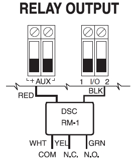
DSC RM-1C single relay module with screw terminals: ✓Now €17.97 ✓Insured Shipping ✓Money Back Guarantee. DSC RM-1 relay. I planned to use the RM1 relay to invoke opening garage door using WSL909 wireless key buttons, there are 5 wires on RM!, Red for (+) Aux, Black for PGM, White for COM at garage door motor and not sure yellow or green (which one?) for other garage door terminal? Yellow is the normally closed contact, green is the normally open ...
PLEASE NOTE THAT EITHER RM1C ULC OR RM2 RELAYS CAN BE USED FOR ULC INSTALLATIONS 15 3G3070 Wiring Diagrams Figure 8 -Connection Details for GSM Supervision Relay and Redundant Fire Alarm Transmission Connection Details for GSM Supervision Relay & Redundant Fire Alarm Transmission 3G3070 1 2 LE 3 4LI 5 6 O1 7 O2 8 O3 9 O4+OC 10 11 12 AS 13 14 15 ...

Dsc rm-1 relay diagram
information... The RM-1 *is not* an EOL power supervision relay and cannot be used as such. The *RM-2* is *designed (and intended for use) as* an EOL power supervision module. In most cases it also needs to be used with a PRM-4W Polarity Reversal Module to ensure the sounders on all the four wire Citroen Relay (2014 - 2018) - fuse box diagram. Year of production: 2014, 2015, 2016, 2017, 2018. Dashboard, left-hand side, fuses Citroen Relay - fuse box ... DSC | RM-1 SINGLE RELAY MODULE WITH WIRE LEADS.
Dsc rm-1 relay diagram. DSC (Digital Security Controls) is a world leader in electronic security. Since the company’s genesis, the experts at DSC have been leading the way. From our revolutionary control panels, to our industry-leading IP alarm monitoring products and now to our sleek, contemporary self-contained wireless panels, DSC has always been front and center ... 3 different input signal setup including dc 0 1 10v pwm and 100k ohm resistor dimming, rm 0 10v the relay dimming receiving module universal on 120vac or 277vac rm 0 10v is connected to the fixture power and to the led driver using the new patented relay dimming method it monitors the power line for messages from End-of-line power supervisory relay (4-wire detectors only) · DSC (Digital Security Controls) is a world leader in electronic security. Since the company’s genesis, the experts at DSC have been leading the way. From our revolutionary control panels, to our industry-leading IP alarm monitoring ... The relay or trigger will activate on Zone Type. The Zone Type is 54 (Fire Reset) the action will automatically be "Close for 2 seconds" when ZT 54 is selected. The output number will either be the relay which was enabled through Output Device Mapping [*79], or will be either Output 17 (trigger 1) or Output 18 (trigger 2).
Recent DSC RM1 - 12VDC End of Line Relay questions, problems & answers. Free expert DIY tips, support, troubleshooting help & repair advice for all Home Security. The DSC RM-2 Installation Manual helps users get started with the DSC RM-2 End of Line Power Supervision Relay. This guide covers the processes for mounting and testing the device. This manual also includes the device's technical specifications and a wiring diagram. Learn how to set up the DSC RM-2. dsc rm 1 relay diagram. enter text from picture page 38 pc v1 unite mingle this knack faculty giving out relay into your land house security systems for obedient safety dsc rm 1 capacity organization relay for smoke and co sensors. dsc talent 832 installation calendar encyclopedia pdf download manualslib. DSC (Digital Security Controls) is a world leader in electronic security. Since the company’s genesis, the experts at DSC have been leading the way. From our revolutionary control panels, to our industry-leading IP alarm monitoring products and now to our sleek, contemporary self-contained wireless panels, DSC has always been front and center ...
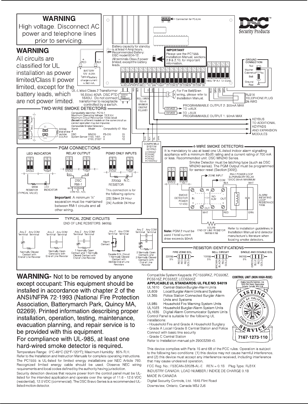
The RM-2 Relay Module is used as an end-of-line (EOL) power supervision module for 4-wire smoke detectors. The RM-2 is used with the Polarity Reversal Module PRM-4W and DSC FSA-410 series smoke detectors. When the PRM-4W reverses polarity on the smoke detector loop to activate all smoke detector sounders, the RM-2 Relay will continue to operate ... DSC RM-1 WHT YEL GRN COM N.C. N.O. AUX AUX NOTE: SMOKE DETECTOR POWER 12 V DC ALARM INITIATING LOOP RESISTANCE 100Ω RM-1 POWER LOOP SUPERVISORY RELAY WHT RED WHT GRN IN COM NO ALM IN OUT OUT BLK Refer to Installation Manual and Smoke Detector Instruction Sheet when positioning detectors. Compatible 2-wire Smoke Detector Timers and Control Relays > General Purpose Relays > Solid State Relays > Carlo Gavazzi Solid State Relays > Hockey Puck Solid State Relays > RM1A Series - Single-Phase - Industrial Load SSR 25A 1PH 24-265VAC SWITCHING 20-280VAC/22-48VDC CONTROL Catalogue No:RM1A23A25 Dimension Diagram Description. The DSC RM-1C is an alarm system accessory for fire alarms and/or burglary alarms. Specifications. Coil Operating Voltage, 12 VDC at 13.33 mA.
DSC Security alarm system wiring walk-through and explanation of panel and devices
The RM-4 Reader Module is a circuit board that creates the connectivity between a reader and an apC or iSTAR controller when third-party card readers are used on a C•CURE System. In addition, the RM-4 Reader Module provides two supervised inputs and two outputs, and can be mounted in any suitable enclosure.

Car Motorcycle 12V Horn Wiring Harness Relay With Ceramic ...
DSC-RM-1. DSC DSC-RM-1. No reviews yet Write a Review ... The supervision relay is installed at the end of the detector power circuit. A break in the detector power circuit or a loss of power de-energizes the power supervision relay, opening the contacts and causing a trouble annunciation at the fire alarm control unit. ...
My Document
DSC. |. RM-1C. Relay Module, 9 to 14 Volt DC, 5 Ampere at 30 Volt DC Contact, 33.3 Milliampere at 12 Volt DC Coil, With Terminal. When you order products from Anixter.com, the order is processed within one to two business days. Orders received during non-business days are processed on the next business day. You have several shipping options for ...
DSC GS3055-IG Installation manual | Manualzz
Use DSC PTD 1640U for Canadian Installa-tions NOTE: Do not connect transformer to a receptacle controlled by a switch. (UL Listed Installations Only) RM-1/RM-2 POWER LOOP SUPERVISORY RELAY T-1 R-1 TIP

PC4020 v3.0 Installation Manual DLS-2 v1.3 - PDF Free Download
How to Install RM4. To install this relay to an alarm, connect the power wires as listed below. See diagrams for connections. Note: If wiring the relay remote from the alarm, use a maximum of 1000 feet [300 meters] of #18AWG or larger wire rated at least 300V. Alarm.

Smoke and CO2 on DSC 832 - DoItYourself.com Community Forums
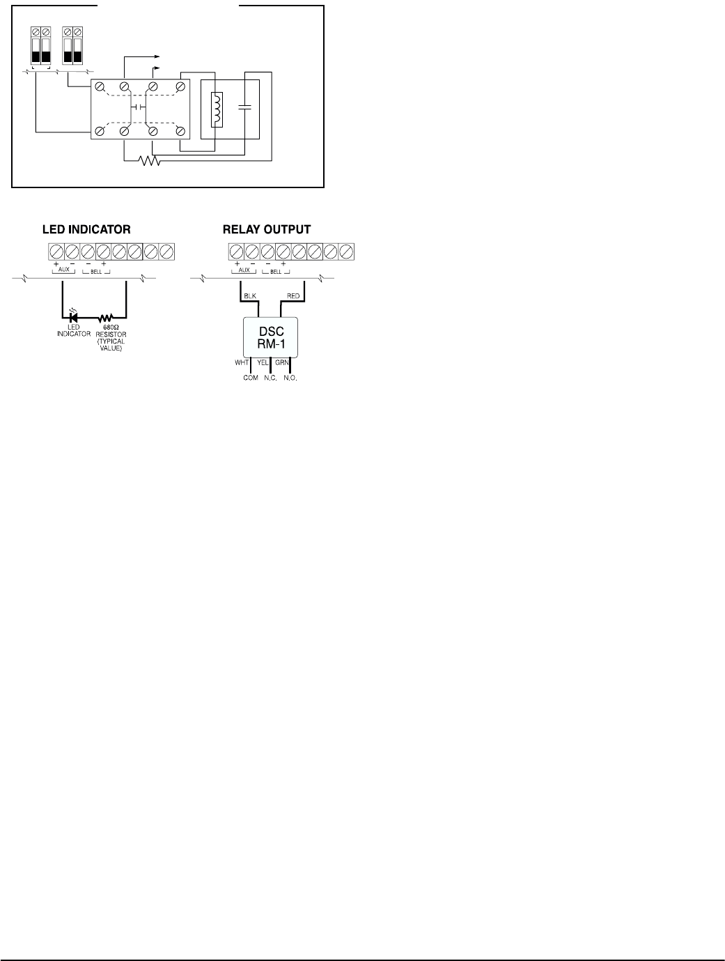
/ PGM terminals should be supervised using an RM-1 relay after the last smoke detector. The RM-1 N.O. contacts (closed with power applied) should be wired in series with the alarm initiating end-of-line resistor so that should power to the detector(s) fail, a fire loop trouble will be initiated. Burglary Zone Wiring Burglary zone definition, (eg.

MR Imaging–derived Oxygen Metabolism and Neovascularization ...
At last if you wish to have new and latest graphic related Fee Best Of Mercedes Benz Wiring Diagrams Freeplease follow us on google plus or save this website, we attempt our best to give you regular update with all new and fresh pics.

Antagonistic Center-Surround Mechanisms for Direction ...
DSC RM-1C Single Relay Module $ 9.95. DSC 12 volt, single pole relay with terminals mounted on a self adhesive pad. Ideal for switching devices that require a clean contact. DSC RM-1C Single Relay Module quantity. Add to cart. SKU: S-DSC-RM-1C Category: Power Tag: DSC. Description.
Pc1555 v2.3 50 300 install
3FE-3FF 1 1 1 1 1 1 1 1 2.3. Connector Pin Assignments The PCL-725 card is equipped with a 37 pin D type connector accessible from the rear plate. Please refer to Figure 2.1 for the location of the connector. The following diagram below shows its pin assignments. Legend: DInL - digital input low, channeln
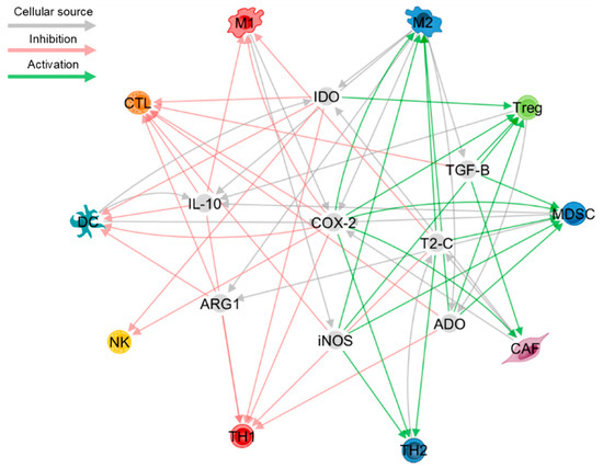
Cells | Free Full-Text | Fine-Tuning the Tumour ...
Wiring and Installation Guidelines Page 7 of 82 Document Edition 2.10 Chapter 1: Power Installation Guidelines This chapter describes the power wiring practices for all Delta Controls Class 2 products.

OSSRD1001A - 1006A Datasheet by TT Electronics/Optek ...
We will be retiring Alexa.com on May 1, 2022. For more information, click here. Log in. Install the Alexa Browser Extension to get free competitive intelligence about millions of websites while you browse the web. checksum.com Competitive Analysis, Marketing Mix and Traffic .

Kantech KT-RM1 Relay
DSC (Digital Security Controls) is a world leader in electronic security. Since the company's genesis, the experts at DSC have been leading the way. From our revolutionary control panels, to our industry-leading IP alarm monitoring products and now to our sleek, contemporary self-contained wireless panels, DSC has always been front and center ...

Kantech KT-RM1 Optional External Isolation Relay for KT-300
Sears Craftsman Model 917.28856 Moser Wiring Diagram. 04.06.2019 04.06.2019. 2010 Dodge Avenger Serpentine Belt Diagram
FCA2015-U1 Serial Digital Alarm Communicator Transmitter ...
Relays DF-52068:A • I-400 General Air Products & Controls, Inc. PAM-1, PAM-2, and PAM-4 Multi-Voltage Relay Modules are encapsulated multi-voltage devices. The PAM-1 relay provides 10.0 Amp Form-C contacts and may be energized by one of three input voltages: 24 VAC, 24 VDC, or 115 VAC. The PAM-2 relay provides 7.0 Amp

DSC RM-1 Power Supervision Relay for 4-wire Smokes
DSC created this device to be used in conjunction with their FSA-410 Photoelectric Smoke Detectors. The device is wired inside the smokes, following a diagram ...
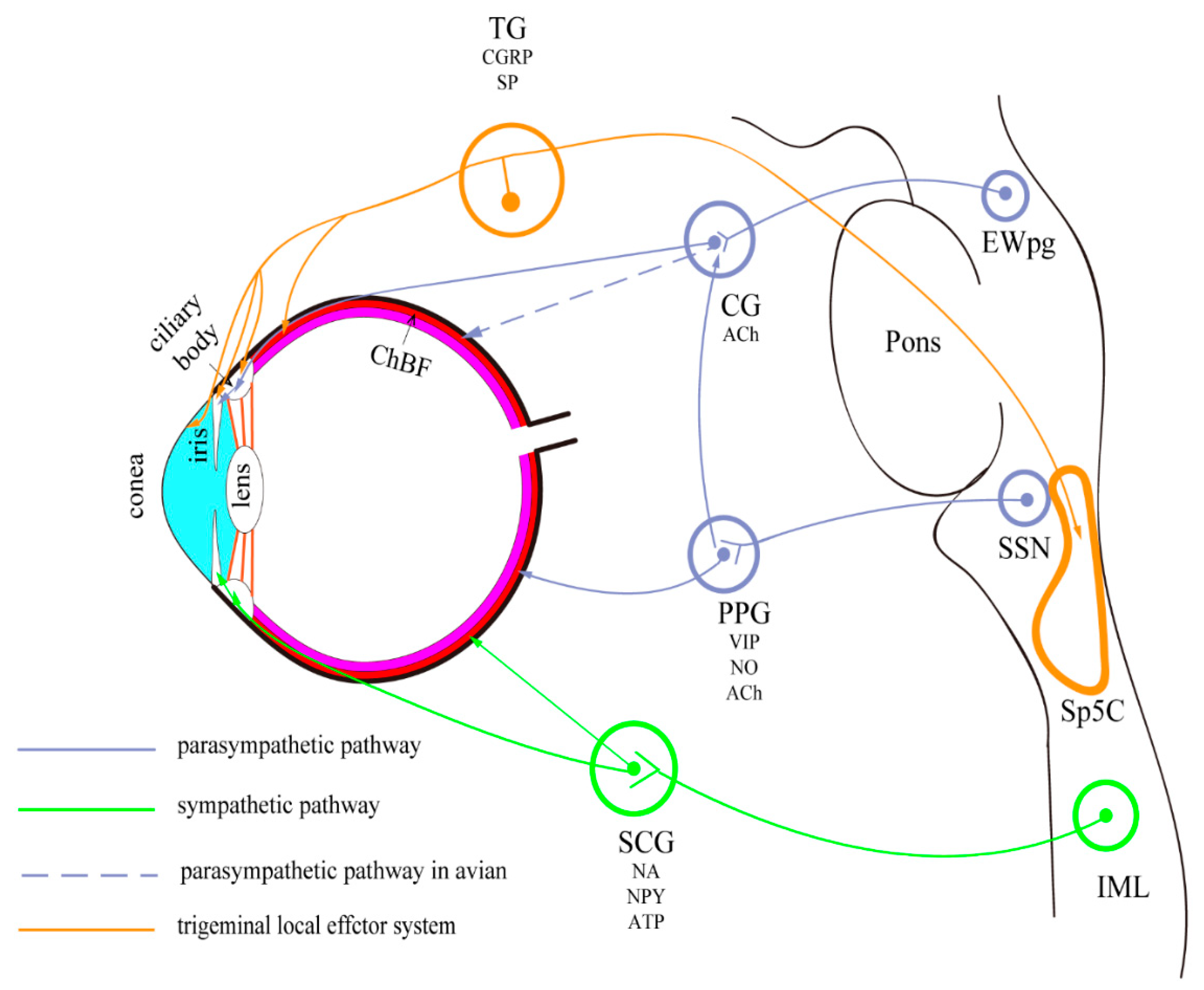
Vision | Free Full-Text | Ocular Autonomic Nervous System: An ...
Model EOLR-1 is an epoxy encapsulated single pull single throw (SPST) normally open relay that is activated by 9 to 40 VDC. This relay can be used as an end of line device in fire alarm systems, e.g., to supervise power supplies. MOUNTING For ease of installation, the EOLR-1 relay may be mounted in a variety of ways. It can be attached to ...
pg
Table CO Detector Ratings Diagram CO Detector Wiring FSAB FSABLST FSABRST FSABT FSABR FSABLRST FSABS FSABRT FSABST FSABRS Current ratings for DSC FSA Series: 25mA T-1 . 4W and DSC FSA series smoke detectors. When the PRM-4W reverses polarity on the smoke detector loop to activate all smoke detector sounders, the RM-2 Relay will continue to ...

PC4010 v3.0 Installation Manual DLS-2 v1.3 - PDF Free Download
diagram wiring diagram pictures, 120 volt coil relay schematic best place to find wiring, circuit breaker wiring diagrams do it yourself help com, 220 volt 3 phase ... 220 volt wiring to 110 automotive diagrams for diagram, online wiring 1 / 13. informa on winnebago, start by selecting the model year of your coach from the,
DSC PC1500 Installation manual | Manualzz
DSC RM-1 Power Supervision Relay for 4-wire Smokes This is a four-wire power supervision relay from DSC for four-wire smoke detectors. You will install this at the end of the four-wire smoke detector's power loop and whenever there is a break in the detector power circuit or a loss of

DSC-RM-1 - SS&Si Dealer Network
Mr Manuals - Manuals and schematics website. The manuals list: 0XD FX manuals 072 DEDICATED BUFFER PEDAL - owner's manual BOMB IDEA DYING BATTERY SIMULATOR PEDAL - owner's manual MORSE DEVICE KILL SWITCH PEDAL - owner's manual 360 SYSTEMS manuals 2470-HD TIME DELAY - operations manual ADVANCED PLAYLISTING …
113G3070 ALARM COMMUNICATOR User Manual USERS MANUAL Digital ...
Shop & learn about the perfect smart home products for your home in 2021. 30-Day No Hassle Returns.

Kantech KT-RM1 Optional External Isolation Relay for KT-300
DSC Security Systems DSC Modules DSC 12V Relay Module, No ULC Part Number RM-1 UPC 80020005 820043011760 Availability In Stock Price $14.99 CAD Unit of Measure EACH Quantity Product Information DSC Form C 12VDC general purpose relay. Customers Also Bought
smoke detectors for nx-8e? - HomeSeer Message Board
As of the time of writing (Aug 27th 2010) the RM-1 wiring is as follows: Black - negative coil Red - positive coil White - common Yellow - normally closed Green - Normally Open. DSC RM-1 Wiring. DSC RM-1 Wiring. As of the time of writing (Aug 27th 2010) the RM-1 wiring is as follows: ... The following page shows a number of different example ...
KT-300 Installation Manual DN1315.book
Jul 05, 2019 · A DSC RM-1 Relay should be used to connect power to the smoke detectors; refer to the hook-up diagram below. Power wiring from the AUX+ / PGM terminals should be supervised using a DSC RM-1 Relay connected after the last smoke detector. Designed with this idea in mind, the PCL Relay Actuator & Isolated D/I card is an IBM PC add-on card that ...

DSC PC 1616 -- Wiring Advice - DoItYourself.com Community Forums
ASC/DSC button ABS/DSC unit (with DSC) Switch center: 34: 5: Instrument cluster control unit Fuel pump control (EKPS) 35: 50: ABS/DSC unit Relay, convertible top drive: 36: 50: Secondary air pump relay: 37: 50: Heating blower relay Blower switch (with IHS) Blower output stage (with IHKA) Electric fan: 38: 10 '95-'99: Fog light relay: 15 ...
My Document
DSC | RM-1 SINGLE RELAY MODULE WITH WIRE LEADS.

DSC RM-1C single relay module with screw terminals
Citroen Relay (2014 - 2018) - fuse box diagram. Year of production: 2014, 2015, 2016, 2017, 2018. Dashboard, left-hand side, fuses Citroen Relay - fuse box ...

Aug - 2016 - NEO - PRM-2W Installation Setup | PDF | Power ...
information... The RM-1 *is not* an EOL power supervision relay and cannot be used as such. The *RM-2* is *designed (and intended for use) as* an EOL power supervision module. In most cases it also needs to be used with a PRM-4W Polarity Reversal Module to ensure the sounders on all the four wire

INSTALLATION MANUAL PC2525. Version PDF Free Download
29008721R001_PowerSeries_Neo_1.0_IG Dsc powerseries neo ...

DSC RM-1C Relay Module - TremTech Electrical Systems
PAD100-RM

DSC PowerSeries NEO Relay & Modules, extensive range of ...
PowerSeries Pro v1.1 reference manual
PC5020 V3.2 Installation Manual
113G3070 ALARM COMMUNICATOR User Manual USERS MANUAL Digital ...

DSC pc2550 v1-3 im eng 29000592 r2 by Sertek Servicios ...
0 Response to "37 dsc rm-1 relay diagram"
Post a Comment