41 radar system block diagram
RADAR SYSTEM BLOCK DIAGRAM . Circulator Receiver Protector Synchronous I/ Q Detector ADC and Signal Processor Display Pulse Generator Mixer Mixer Coupler Coupler Oscillator LO PA Radar LNA. ISO 9001 : 2008 Registered Pasternack Enterprises, Inc. P.o. Box 16759, Irvine, CA 92623 Phone: (866) 727-8376 or (949) 261-1920 Fax: (949) 261-7451 Radar range equation for search (S/N = signal to noise ratio) • S/N of target can be enhanced by – Higher transmitted power P. av – Lower system losses L – Minimize system temperature T. s. R k T L P A t S/N . s 4 av e s. Ω = 4π σ. The design of radar transmitter/receiver affects these three parameters directly. P. av = average power ...
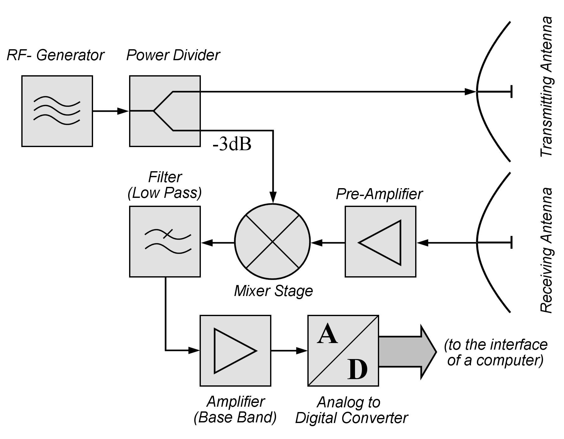
This block diagram may be used for your own lessons but there are no block labels in the animation and there is no background image (landscape). These block labels can be placed in an own layer over the animation in e.g. MS-PowerPoint with text boxes in your own language version. For a presentation with a light background color, you can use the following animation: pulseradar-bright.gif (940×650px, 683 kByte).
Radar system block diagram
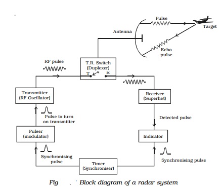
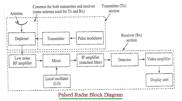
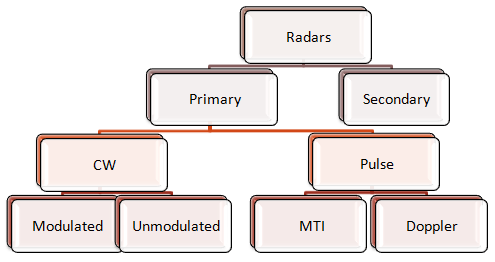
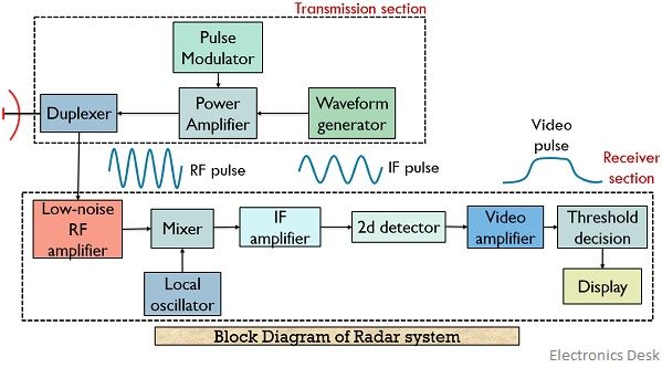
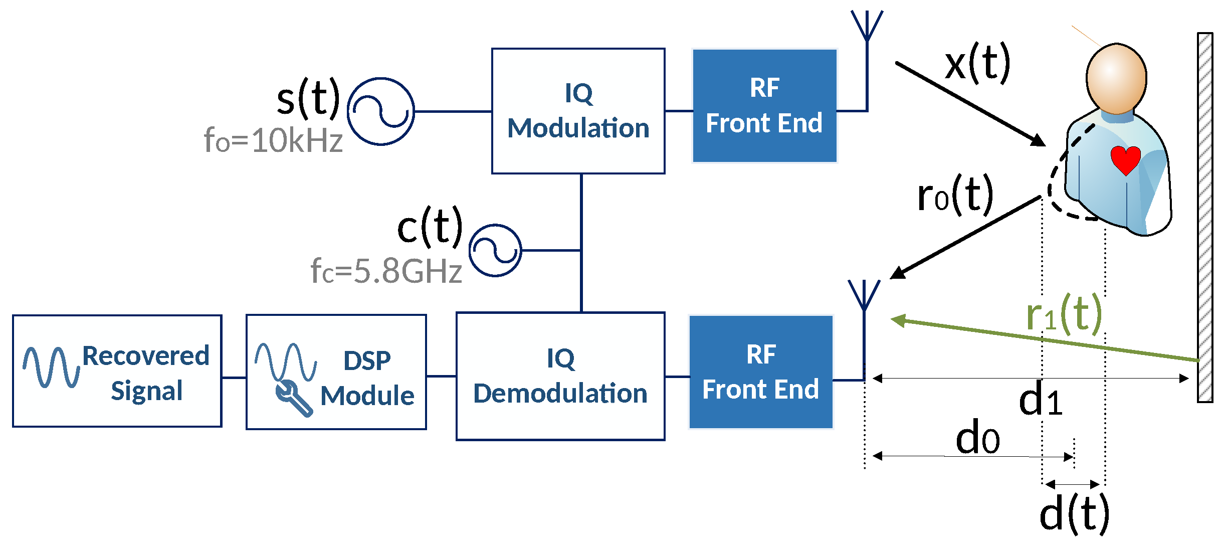
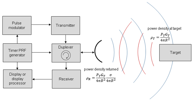
Block Diagram of Pulse Radar. Pulse Radar uses single Antenna for both transmitting and receiving of signals with the help of Duplexer. Following is the block diagram of Pulse Radar −. Let us now see the function of each block of Pulse Radar −. Pulse Modulator − It produces a pulse-modulated signal and it is applied to the Transmitter. Bistatic Radar System: A bistatic radar system utilizes independent antennas for transmission and reception of the signal. Block Diagram of Radar System. The figure below shows the block diagram representation of radar: We know that a radar system has a transmitting and receiving section. And both the sections perform their respective operation. The baseband in-phase (I) and quadrature-phase (Q) signals are digitized using a pair of A/D converters The synchronous detector is also referred to as a quadrature channel receiver, quadrature detector, I/Q demodulator, or coherent detector. Well, If I turn the whole construct by 90° ...
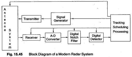
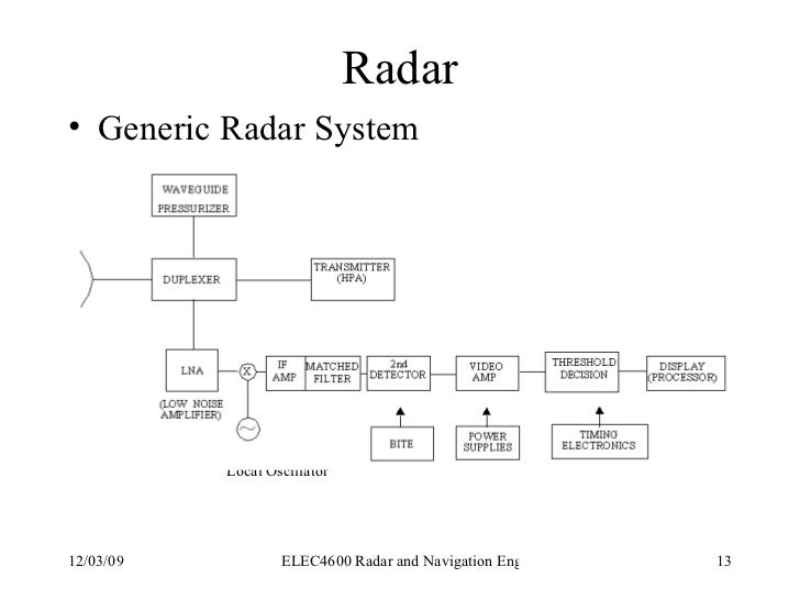
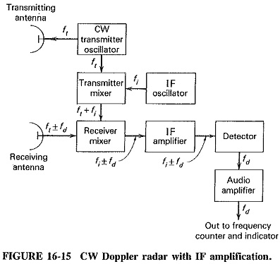
Radar system block diagram. The sub-level block diagram shown in Figure 3 displays the EW digital radar receiver in more detail than Figure 1. Block 1 mixes an analog RF signal with an analog LO frequency from Block 2 to produce an analog intermediate frequency (IF). The IF signal is sampled by Block 3 to be processed by Block 4. In addition, Block 4 controls the LO frequency transmitted by operation of the radar. The functional block diagram (fig 2) depicts the eight major systems of the TTR which are: synchronizing system, transmitting system, RF (monopulse duplexer) and antenna system, receiver system, ranging system, antenna position system, presentation system, and RF and IF testing system. A The block diagram of Figure 16-4 shows the arrangement of a typical high-power Pulsed Radar System Block Diagram. The trigger source provides pulses for the modulator. The modulator provides rectangular voltage pulses used as the supply voltage for the output tube, switching it ON and OFF as required. Radar Block Diagram • This receiver is a superheterodyne receiver because of the intermediate frequency (IF) amplifier. (Similar to Figure 1.4 in Skolnik.) • Coherent radar uses the same local oscillator reference for transmit and receive.
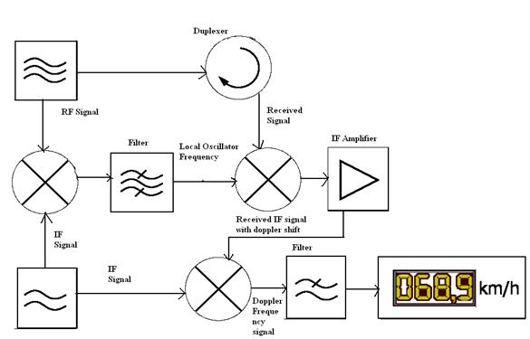
Figure 2. Block Diagram of Coffee-Can Radar System The block diagram shows the three key parts of this system: the RF electronics (green), audio frequency electronics (blue), and digital signal processing software. The modulator generates the sync-pulse which is used when measuring the range of a target. Note that Block Diagram Of The Realized 24ghz Doppler Radar Sensor I Q Mixer Scientific. Code And Circuit Diagram For Radar Using Ultrasonic Sensor Harsh Sharma Technicals. Block diagram of the radar sensor circuit uses a branch line power scientific proposed how to build economy detector automotive diy infrared system 2 4 ghz doppler integrated on ... Pulsed Radar System Block Diagram: A very Pulsed Radar System Block Diagram set was shown in Figure 16-1. A more detailed block diagram will now be given, and it will then be possible to compare some of the circuits used with those treated in other contexts and to discuss in detail those circuits peculiar to radar. Block diagram and description: The baseband in-phase (I) and quadrature-phase (Q) signals are digitized using a pair of A/D converters The synchronous detector is also referred to as a quadrature channel receiver, quadrature detector, I/Q demodulator, or coherent detector. Well, If I turn the whole construct by 90° ...
Bistatic Radar System: A bistatic radar system utilizes independent antennas for transmission and reception of the signal. Block Diagram of Radar System. The figure below shows the block diagram representation of radar: We know that a radar system has a transmitting and receiving section. And both the sections perform their respective operation. Block Diagram of Pulse Radar. Pulse Radar uses single Antenna for both transmitting and receiving of signals with the help of Duplexer. Following is the block diagram of Pulse Radar −. Let us now see the function of each block of Pulse Radar −. Pulse Modulator − It produces a pulse-modulated signal and it is applied to the Transmitter.


/Year_4/ECE%20451%20L_Radar_Eng_and_Facsimile/Introduction_to_Radar/Images/Radar%20Block%20Diagram.PNG)


/Year_5/ELC-544E-Radar%20Systems%20and%20Satellite/RADAR/Images/Radar%20Block_Diagram(1).GIF)


0 Response to "41 radar system block diagram"
Post a Comment