40 extended free body diagram
But when we draw a free body diagram for a ladder lying against the wall. The normal force is like slanted towards the wall. No, the normal force between the wall and ladder is always perpendicular to the wall. By definition! But if there's friction on that wall, the wall may also exert a vertical force on the ladder. Aug 1, 2010.
23.11.2021 · In the part of the question that is already posted, we are asked to "Draw an extended free body diagram at an instant after they are released but before they hit the floor." That has been done by OP. Next we are given three student statements without any instructions on what to do with them. Are we supposed to find which are True and which are False? Are we supposed …
Draw an extended free body diagram of the fishing rod. In order to hold the rod tip up, the hand in front must lift up while the hand in back pushes down. (As measured from the bottom rear of the rod.) 13: Draw an extended free body diagram of the 5.5 m long beam. There is a reaction force, R, at the wall where the beam touches it.

Extended free body diagram
For the Extended Free Body Diagram, these same four forces are applied at the following locations: • W - The Weight is applied at the Center-of-Mass Point . • T - The Tension is applied at the upper left end of the rod. • H H - The horizontal hinge force is applied at pivot point on the hinge.
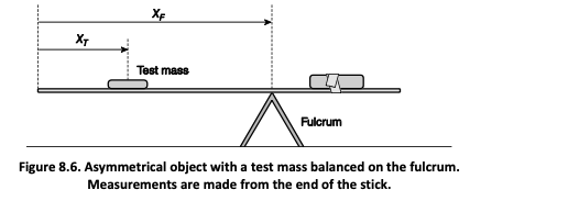
Here, the free-body diagram for an extended rigid body helps us identify external torques. Example 12.3. The Torque Balance Three masses are attached to a uniform meter stick, as shown in Figure 12.9. The mass of the meter stick is 150.0 g and the masses to the left of the fulcrum are m 1 = 50.0 g m 1 = 50.0 g and m 2 = 75.0 g. m 2 = 75.0 g.
In the spaces provided, draw an extended free-body diagram for each layer. For any contact forces, indicate the surface on which the force is applied by placing the tip of the arrow that represents that force at that surface. Each force should be labeled. B. Rank all of the vertical forces on your free-body diagrams according to magnitude, from ...
Extended free body diagram.
Sketch a free-body diagram for the heavier object. Choose a positive direction, and apply Newton's Second Law. ∑. FMa = v v +− =+ Mg F Ma. T. 2. F. T. 2. Mg. a Choose positive down this time, to match the object's acceleration. Acceleration in an Atwood's machine II. 15. Step 3: Analyze the pulley. Sketch a free-body diagram for the ...
In physics and engineering, a free body diagram (force diagram, or FBD) is a graphical illustration used to visualize the applied forces, moments, and resulting reactions on a body in a given condition. They depict a body or connected bodies with all the applied forces and moments, and reactions, which act on the body (ies).
Here, the free-body diagram for an extended rigid body helps us identify external torques. Example The Torque Balance. Three masses are attached to a uniform meter stick, as shown in Figure. The mass of the meter stick is 150.0 g and the masses to the left of the fulcrum are [latex]{m}_{1}=50.0\,\text{g}[/latex] and [latex]{m}_{2}=75.0\,\text{g ...
A free-body diagram is a representation of an object with all the forces that act on it. The external environment (other objects, the floor on which the object sits, etc.), as well as the forces that the object exerts on other objects, are omitted in a free-body diagram. Below you can see an example of a free-body diagram:
Basic static equilibrium examples that emphasize drawing the free body diagram, choosing an axis, and evaluating torque without bothering to work out the num...
A free-body diagram is a special example of the vector diagrams that were discussed in an earlier unit. These diagrams will be used throughout our study of physics. The size of the arrow in a free-body diagram reflects the magnitude of the force. The direction of the arrow shows the direction that the force is acting.
What is free body diagram in physics? In physics and engineering, a free body diagram (force diagram, or FBD) is a graphical illustration used to visualize the applied forces, movements, and resulting reactions on a body in a given condition. What is an extended free body diagram? An extended free body diagram is used to show forces and ...
Extended Free Body Diagram Example - YouTube Cliff and Will are carrying a 2.0 m board (uniform so center of mass is in the middle) of mass 71kg. Will is supporting the board on his shoulder at one...
A free-body diagram is a graphic, dematerialized, symbolic representation of the body (structure, element or segment of an element) in which all connecting "pieces" have been removed. Features of Free Body Diagram A free-body diagram is a diagram that is modified as the problem is solved.
Draw an extended free- body diagram for this situation. Again using the rod as your pivot point determine the distance to be used for calculating the torques due to each force. Then decide whether the torque due to each point is clockwise or counterclockwise. Predict what the tension in the cable will be as measured by the spring scale.
2. Draw a free body diagram accounting for all external forces and couples. Show the resulting inertia forces and couple (typically on a separate kinetic diagram). 3. Compute the mass moment of inertia I G or I O. 5. Use kinematics if there are more than three unknowns (since the equations of motion allow for only three unknowns). 4.
An introduction to developing an extended free body diagram for torque analysis.

Nov 3 homework
draw an extended free body diagram for the pulley and pulley at hanger system (see the diagrams to the right) remembering that the falling weight is undergoing acceleration (but not at gl, the linear acceleration is related to the angulor acceleration by and torque is related to force by tf, we have. hanger pulley mass hanger: mg-t-m,a m,g t-m,ra …
Torque
A free-body diagram is a sketch of an object of interest with all the surrounding objects stripped away and all of the forces acting on the body shown. The drawing of a free-body diagram is an important step in the solving of mechanics problems since it helps to visualize all the forces acting on a single object.
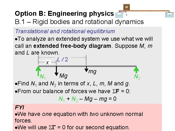
Option b engineering physics b 1 rigid bodies
Draw a sketch and free-body diagram showing the forces involved. The free-body diagram is similar to the no-slipping case except for the friction force, which is kinetic instead of static. Use Newton's second law to solve for the acceleration in the x-direction. Use Newton's second law of rotation to solve for the angular acceleration. Solution
Ppt - chapter 12. rotation of a rigid body powerpoint ...
Tutorial for drawing an extended free body diagram.

Statics - general physcis i - quizzes - docsity
Free body diagram at x 1: Free body diagram at x 2: There are 5 forces acting: The external force, F e, to the right. The force due to k 1. If x 1 increases, k 1 elongates which causes a force at x 1 to the left. The resulting force is k 1 ·x 1 to the left. The force due to b 1.
Name team # ______ date: ______
An extended free body diagram is used to show forces and distances on the same diagram. This YouTube video can be found at http://goo.gl/4Bj06P This information shown below is the non-video, abreviated,version of the YouTube video above. This is what a typical problem might look like.

Free body diagram - wikipedia
Conceptual course introduction to the extended Free Body Diagram used in torque analysis problems.
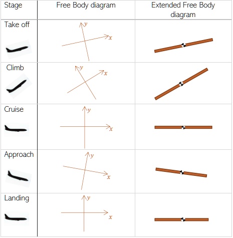
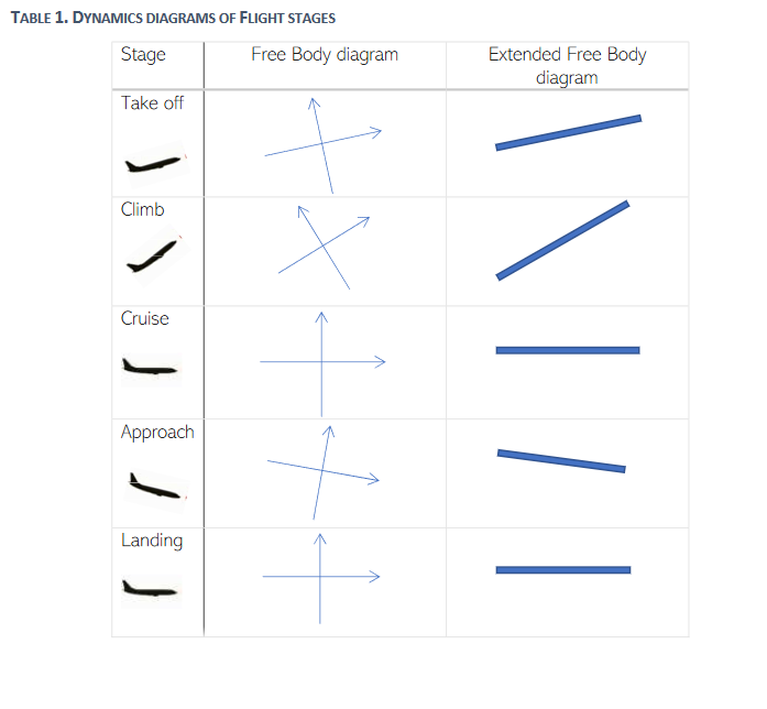
Solved:stage free body diagram extended free body dlagram ...
Your grades could look better! All our academic papers are written from scratch. All our clients are privileged to have all their academic papers written from scratch.
Solved 1. draw an extended free body diagram for the setup ...
Get 24⁄7 customer support help when you place a homework help service order with us. We will guide you on how to place your essay help, proofreading and editing your draft – fixing the grammar, spelling, or formatting of your paper easily and cheaply.

Chapter 10 - rotational motion i: a new kind of motion ...
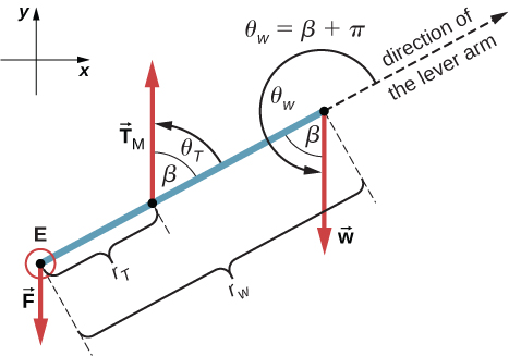
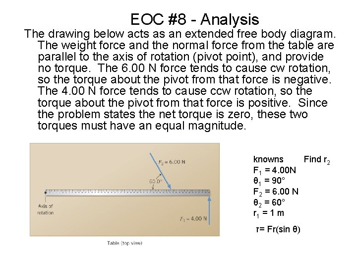
The second picture of the rod shows the extended free-body diagram of the rod, showing all the forces acting on the rod and where they are applied. The force of gravity is shown in green, the two components of the force of tension are shown in blue, and the two components of the hinge force are shown in red. ...

Chap 12.3 - extended free body diagrams (a)
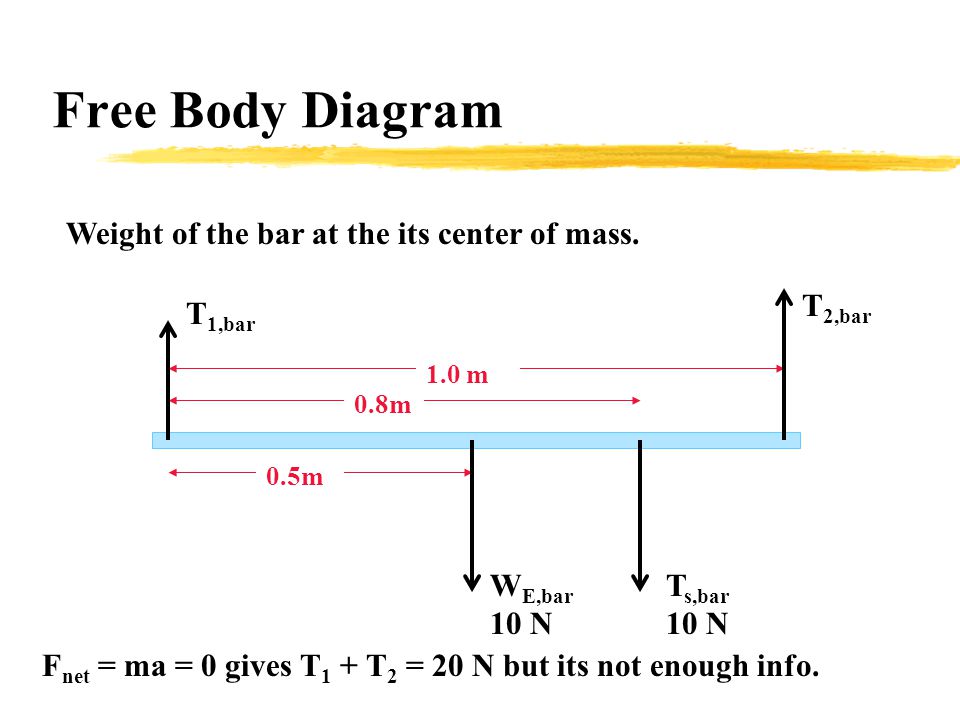
The rst step, as always, is drawing the extended free body diagram of the system (extended because we are dealing with a rotational system and therefore the distance from the pivot is signi cant). 1 Edited by Abid H. Mujtaba (2016) l mg Fpx Fpy There are two forces acting on the bar. Its weight, which acts at the bar’s center of mass/gravity, and a force of unknown magnitude and …
12.2 examples of static equilibrium | university physics volume 1
I know that I need to create an extended free body diagram and I understand how to get all the equations from the diagram. BUT I don't know what to do when it comes time to use torque and find tension Homework Equations T = Ialpha The Attempt at a Solution x-component : N - Tcos(35) = 0 y-component : Tsin(35) + U - 2.5g = 0
Types of forces and free body diagrams
Free-body diagrams have been used in examples throughout this chapter. Remember that a free-body diagram must only include the external forces acting on the body of interest. Once we have drawn an accurate free-body diagram, we can apply Newton's first law if the body is in equilibrium (balanced forces; that is, F net = 0 F net = 0 ) or ...

Airplane wing free body diagram, vintage illustration stock ...
A free-body diagram can be drawn very simply, with squares and arrows, or you can make it much more complex. The only requirement is that you or someone else looking at it should be able to understand what the diagram is telling. A free-body diagram (FBD) is a representation of a certain object showing all of the external forces that acts on it.
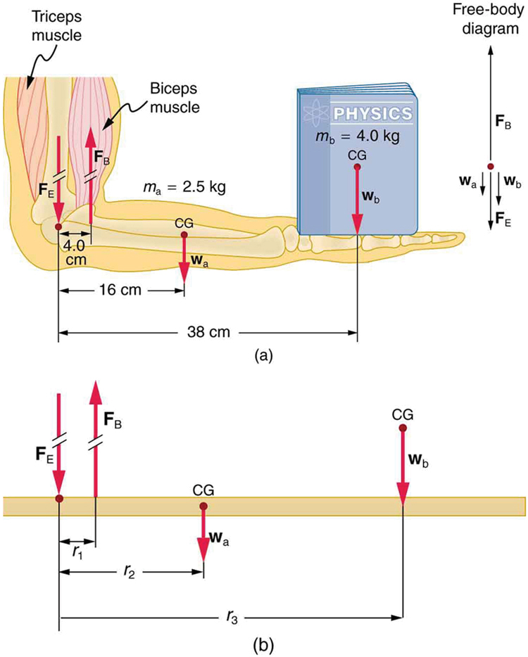
Forces and torques in muscles and joints | physics
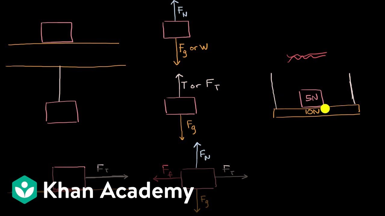
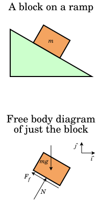
And to be clear, this five newtons, this is equal to the weight, the magnitude of the weight of the object. So that was pretty straightforward, the free body diagram for just the block. And it's really important to see that, because notice, in the free body diagram, all you see is the block. But now let's draw the free body diagram for the shelf.

Torque solution tools
✓ solved: chapter 12, problem 6 - fundamentals of physics ...
Effect on net torque and net force on spools | physics forums

The free body diagram of the chevbot extended to 2d ...

Free body diagram - aerospace applications | stress ebook llc.
11/1 rotation, torque begin rotational dynamics read ch 9 ...
Free body diagram - wikipedia
Fnt 7.3.2-6: fa16: phys-2a sec 01 - fund of physics
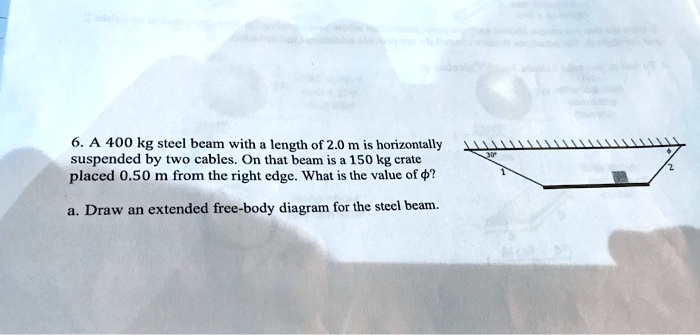
A 400 kg steel beam with length of 2.0 m is horizontal ...
Free-body diagram

Torque and equilibrium questions
Torque
Torque and equilibrium questions

Free body diagram of a two-segment model of a gymnast ...
Chapter 9 torque student learning objectives to extend
Include an original free body diagram and an original | chegg.com
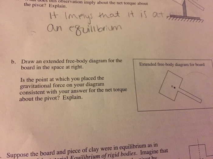
Solved b. draw an extended free-body diagram for the board ...

Rotation. - ppt download
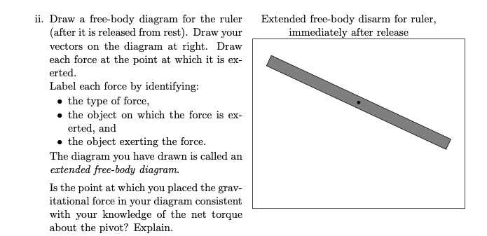
Solved:draw free-body diagram for the ruler (after it is ...
Why the weight force is not included in this free-body ...
Free body diagrams: determining internal forces (cut method ...
Why the weight force is not included in this free-body ...
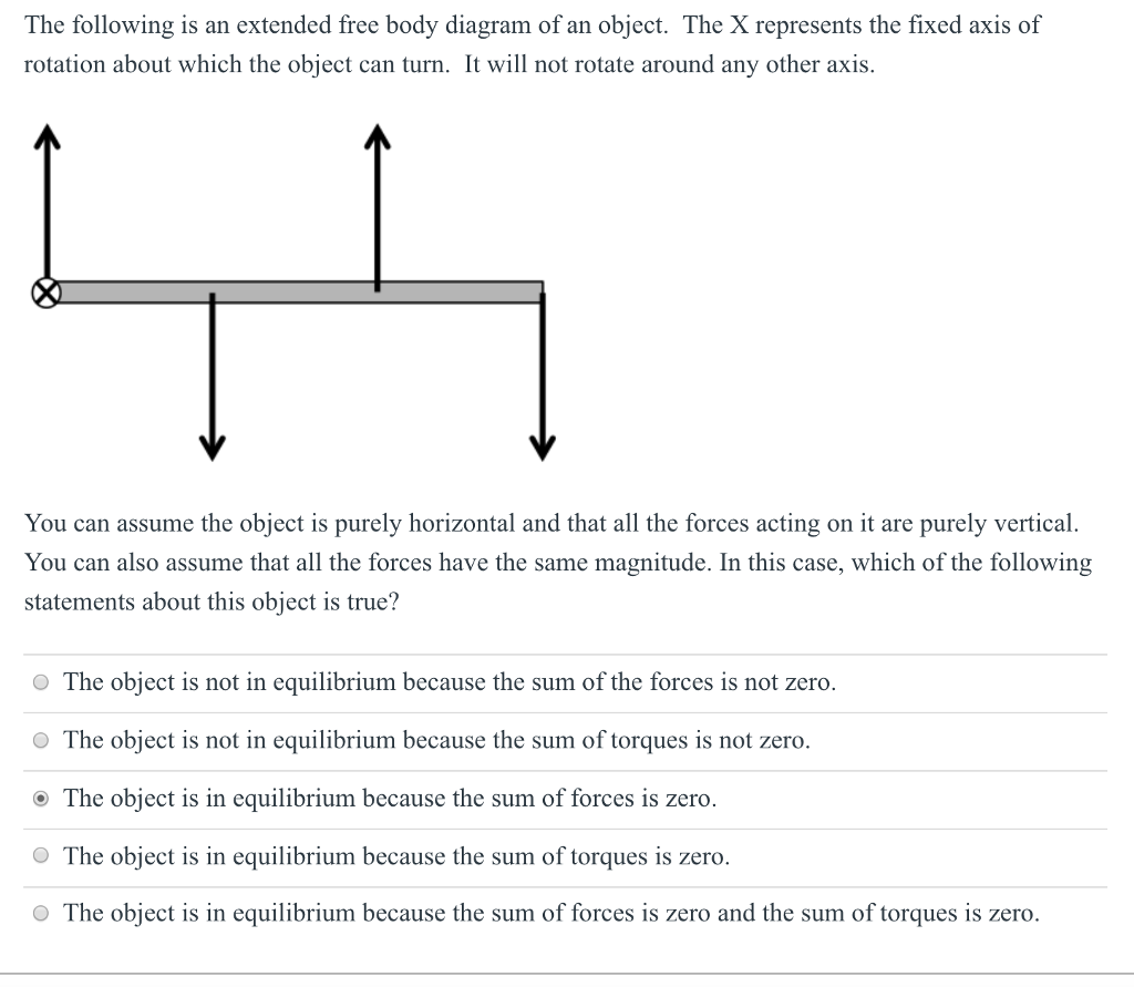
Solved the following is an extended free body diagram of an ...

A) draw fully labelled free body and extended free body ...
0 Response to "40 extended free body diagram"
Post a Comment