39 oil catch can installation diagram
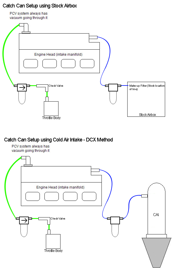
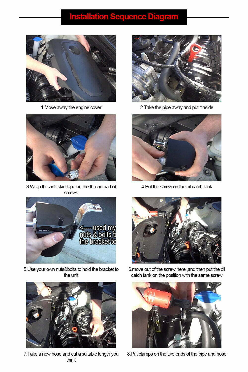
In this installation guide we have provided step by step instructions to remove the necessary OEM components and install the CorkSport Performance Oil Catch Can. Advisory: Working under the vehicle requires a safe and sturdy location for the vehicle to sit on jackstands. The engine bay will be hot after recent vehicle operation. Alright guys, here is a quick walk through and explanation of the PCV system in the 1.6 Turbocharged Gamma motor. We have been seeing a lot of confusion on t...
SG613020 Trax by SAAS Oil Press/Water Temp Install Guide. Installation and Troubleshooting guide Trax by SAAS Oil Pressure 140 psi and Water Temp 40 - 120 deg gauges. (180kb)
Oil catch can installation diagram
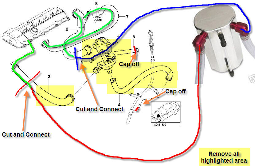
Mishimoto offers installation guides and installation videos for radiators, intercoolers, oil coolers, catch cans, and more for your vehicle. 0% financing available for 3 months - This week only! FREE SHIPPING OVER $100 Strong and durable: The catch can is made of high-quality aluminum. That is why it’s light but sturdy and can take high heat and pressure. It’s durable and easy to set up too. Better filtration: The catch can is better to trap oil residue and moisture. If you can install another PCV valve, then the performance will improve moreâ€"the thing I like about it most. the diagram at right) found on the 3-Series (M52/M54) engines. This catch can kit simply runs in-line with the crankcase breather tube to catch unwanted materials from entering the CCV, intake system, and oil pan. All OEM CCV functionality is still retained. Plumbing of the catch can with the CCV is shown at right.
Oil catch can installation diagram. Now go back and tighten the bolts that secure the catch can to the bracket. 23. The excess hose on the CCV-side can allows for easy access to the oil filler cap when it's time to perform service. CONTINUED ON NEXT PAGE 2015-2016 WRX BAFFLED CATCH CAN INSTALLATION GUIDE Gen 2 Oil Catch Can by McNally Gen 2 CC written installation instructions Gen 2 CC written installation diagram Gen 2 CC written installation diagram for FORD 1.6L - 2.0L -2.3L PFDI Engines Gen 2 CC written installation diagram for FORD 3.5L - 2.7L GTDI Engines Gen 2 CC written installation diagram for FORD 5.0L - 7.3L PFDI Engines Oil Catch Cans and PCV Breathers and Accessories Dual Port with Breather 8AN 10AN 12AN valve cover attachments, weld bungs, hoses, fittings and more! For use with LS1 LT1 Coyote Mod Motor LS2 LS3 LS4 LS6 LS7 LSA LS9 LSX 4.8 5.3 6.0 6.2 SBC BBC SBF BBF engines Our direct fit oil catch can kits feature specific brackets and hoses for an easy bolt-in installation. These catch cans are fully serviceable, so you can clean them yourself. It is important to filter oil particles from the PCV/CCV systems and protect your intake from harmful blow-by.
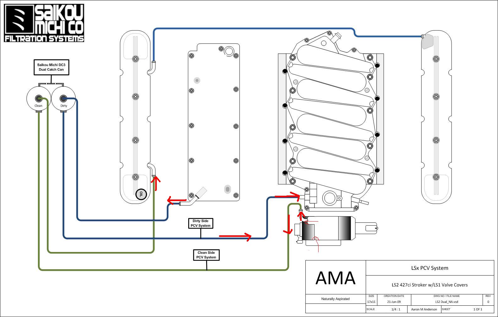
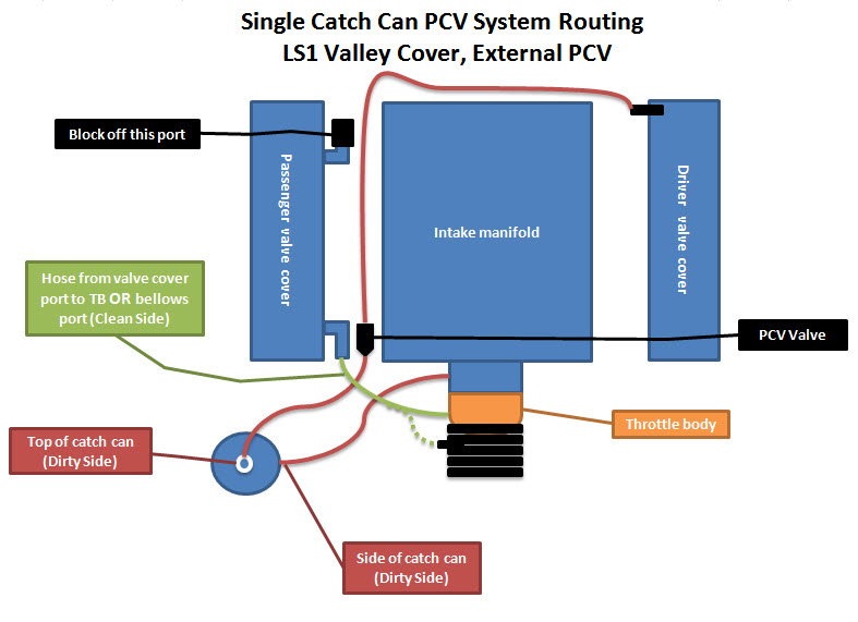
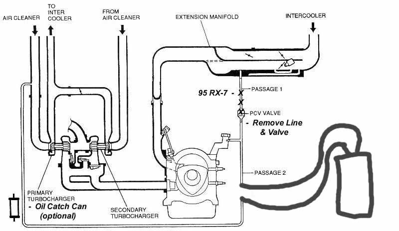
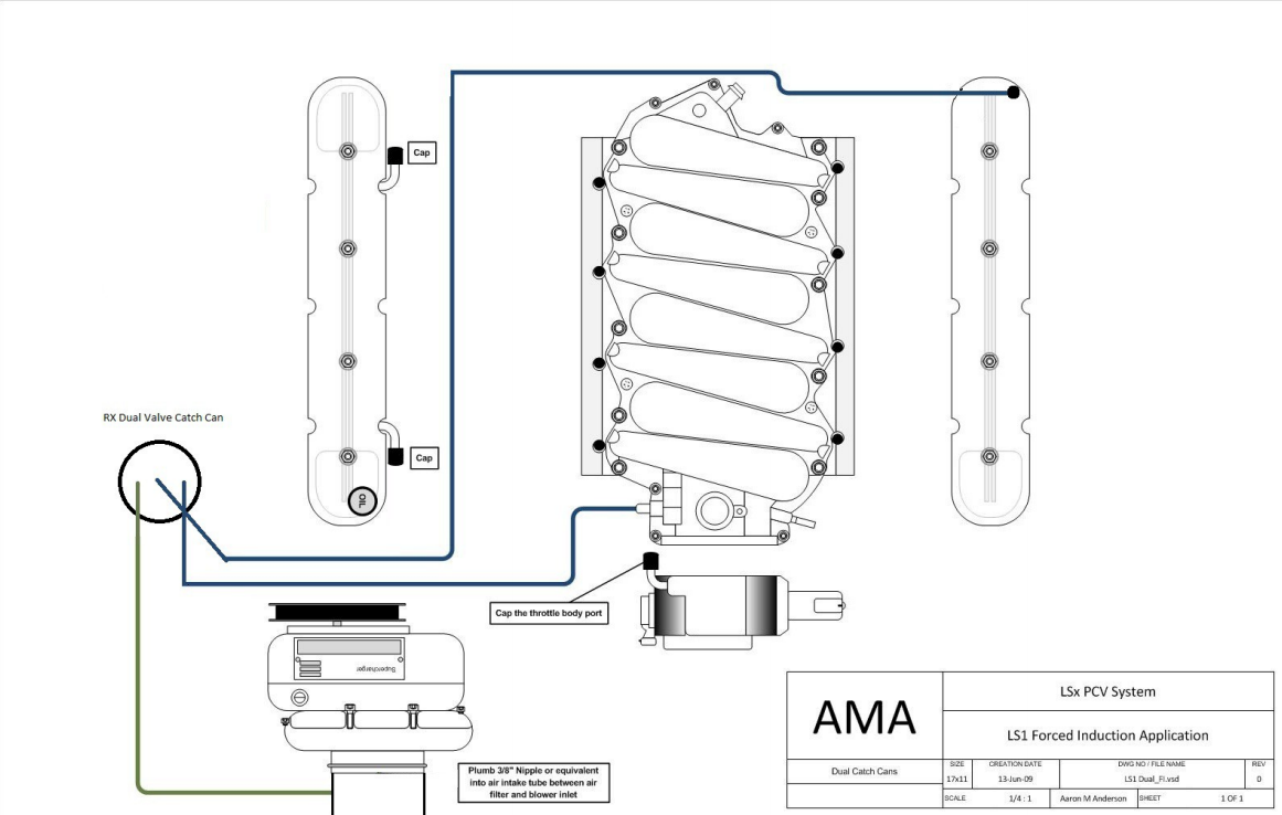
FBM S2000 8.8 Rear Installation Instructions. FBM S2000 H11 Head Stud Installation Instructions. FBM S2000 V160 Hardware Installation Instructions. FBM Supra V160 Installation Instructions. S2000 Dual Pump Wiring Diagram Installation Instructions. S2000 Stage 1 Installation Instructions. S2000 Surge Tank Diagram Installation Instructions. Performance Baffled Oil Catch Can & Oil Drain System Installation Guide Proper service and repair procedures are vital to the safe, reliable operation of all motor vehicles as well as the personal safety of those performing the repairs. RX Catch Can installation& PCV system The LS based motors have a PCV system that at best is pretty ineffective. This allows oil mist to enter the intake manifold causing undue carbon buildup on the piston tops & valve surfaces & detonation from the contaminated air charge. The catch can goes *This install diagram is strictly for the Subaru WRX, routing is different for STI. Please refer to STI diagram for details. Subaru WrX baffled Oil CatCh Can SyStem, 2008-2014 INSTALLATION DIAGRAM LEGEND Dirty "In" Lines Clean "Out" Lines 5/8" to 1/2" Adapter Overlapping Hoses 3/8" x 3/8" Wpt Adapter 1/2" X 3/8" Npt 90° Adapter
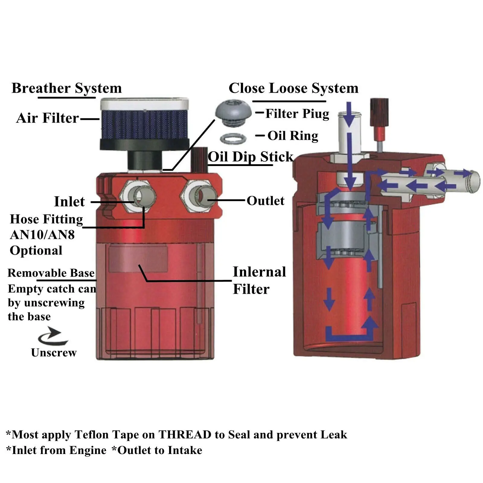
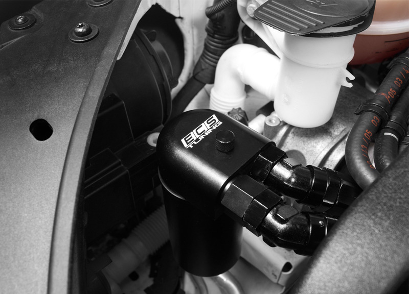
BMW E9X N54 CATCH CAN & DRAIN SYSTEM INSTALLATION GUIDE T#553499 Step 2: 10mm Socket & Ratchet Hose fittings Hose fittings INSTALLING THE CATCH CAN SYSTEM LH Side Kits: RH Side Kits: Install the catch can into the bracket by doing the following: • Unthread the catch can reservoir and remove the O-ring from the catch can separator. It has a mesh screen and filter material that traps the oil and vapor. It also has an easily accessible drain. To get started installing, run lines from each vent on the LS valve covers which will route up to the catch can that has fittings on either side. The catch can will be mounted somewhere in the engine bay. OIL CATCH CAN 111506 Thank you for purchasing the ALTA Performance Oil Catch Can. Installation of this kit should only be performed by persons experienced in the installation and proper operation of MINI Cooper drivetrain systems. NPT Fitting Education: Included with this kit are NPT fittings. NPT stands for National Pipe thread Taper. Air Oil Separator Kits - Listed by Vehicle 2002 - 2007 WRX/STi V2 Top Mount Intercooler (S0714-1)Front Mount Intercooler (S0715-1) 2008 - 2014 STI V2 Top Mount Intercooler (S0720: Replaced S0713-1)Front Mount Intercooler / Stock Location Turbo (S0720: Replaced S0716-1)Front Mount Intercooler / Rotated Turbo (S0720-1: R
There are a few different designs when it comes to oil catch cans. Oil separators are included in this category and are used in line with the PCV system on v...
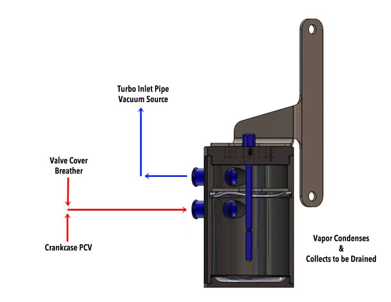
The diagram below illustrates the basics of how a catch can works. The purple arrow represents the air/oil blow-by mixture coming in from the crankcase. It enters the catch can where the oil is collected at the bottom. The air is forced through a media, which filters out additional contaminants, before exiting the catch can as cleaned air ...

INSTALLATION INSTRUCTIONS OIL CATCH CAN KIT 2007+ TOYOTA TUNDRA ENGINE: 5.7L 3UR-FE Open the hood. To release the engine cover, lift up and remove. Note the 3 holes in the factory sheet metal where the catch can bracket will be mounted. This area is located in the front between the radiator

The catch cans hold 4oz until liquid shows on the oil sight (drain now). 6oz is maximum capacity (half way on the sight), and at 8oz the can is completely full (sight is full) and will be bypass the collected oil. Some fill fast, some slow, but it is extremely important to not let the can overfill and it is up to the owner to be in charge of this.

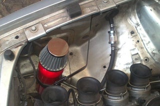
The catch can described in this article will sort of mimic the same principle, although the catch can will vent to open atmosphere. The reason for this is particular, my car no longer is fuel injected, and instead uses carburetors, so the valve cover was disconnected - and in being so, oil would soil the engine bay.
Catch Can Diagram. Amarante Pruvost. November 14, 2021. November 14, 2021. Gen 2 Oil Catch Can by McNally Gen 2 CC written installation instructions Gen 2 CC written installation diagram Gen 2 CC written installation diagram for FORD 16L - 20L -23L PFDI Engines Gen 2 CC written installation diagram for FORD 35L - 27L GTDI Engines Gen 2 CC ...

plug and play diagram above for ford ecoboost the 2014's and earlier do not use the adapter. 2015 and up ford 2.7 and 3.5 css kit we are the original designers of the new system in 2018 a 5 chamber twin can ultimate catch can system..

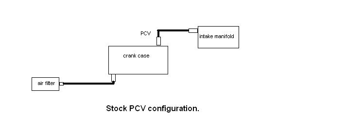
Oil catch cans and breather tanks look similar and do similar jobs, but they serve different purposes. Oil Catch Cans Normally, the PCV (positive crankcase ventilation) valve uses intake vacuum to relieve the pressure inside your crankcase, but that can result in oil mist and other blow-by contaminants building up on the valve and pistons, especially in direct-injection engines.

A catch can works by separating the oil out of the air that comes from the crankcase or valve covers and holds that oil inside of itself, not allowing it to continue into the motor or air. Depending on the type of catch can setup you have chosen to go with will depend on how your catch can works.

2006 STI. CGM. IMO in order to maintain stock functionality of the PCV system and clean all the recirc gasses, you must install two separate catch cans. One will splice between the crankcase and the PCV vavle and the other will splice in between the intake ducting and the T to the valvecovers.

Black Friday Sale 11/23/21 through 11/28/21. $40.00 off Catch Can kits and $20.00 off Insolators.

the diagram at right) found on the 3-Series (M52/M54) engines. This catch can kit simply runs in-line with the crankcase breather tube to catch unwanted materials from entering the CCV, intake system, and oil pan. All OEM CCV functionality is still retained. Plumbing of the catch can with the CCV is shown at right.
Strong and durable: The catch can is made of high-quality aluminum. That is why it’s light but sturdy and can take high heat and pressure. It’s durable and easy to set up too. Better filtration: The catch can is better to trap oil residue and moisture. If you can install another PCV valve, then the performance will improve moreâ€"the thing I like about it most.

Mishimoto offers installation guides and installation videos for radiators, intercoolers, oil coolers, catch cans, and more for your vehicle. 0% financing available for 3 months - This week only! FREE SHIPPING OVER $100


0 Response to "39 oil catch can installation diagram"
Post a Comment