38 nitrous relay wiring diagram
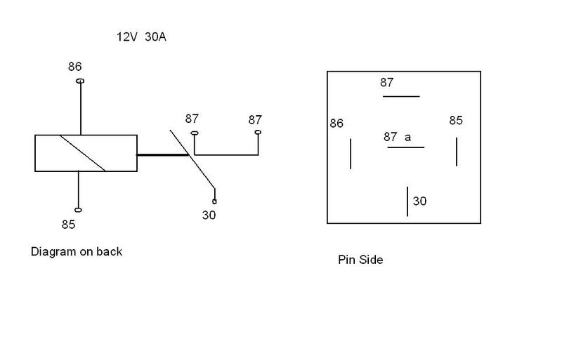
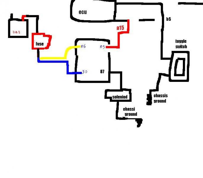
I preface this post by saying I know very little about 12 volt electronics, but I'm working hard to learn. I've had a nitrous oxide system installed by a performance shop that includes an electric bottle warmer that is controlled by a pressure switch and relay. What I'd like to do is wire in an indicator light to let me know when the relay is either open or closed. It doesn't matter to me which way the light indicates. The solution that seems the simplest is to run terminal 85 to a bulb, ...
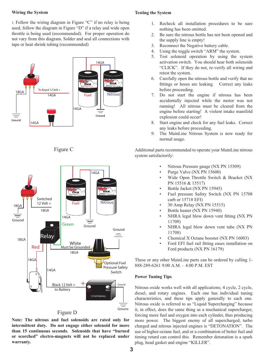
If you are upgrading your existing system, do not follow the wiring diagram from your original instructions. Use only the diagram shown here. Begin by mounting ...1 page
Yes, you need a relay. Search the web for a typical Nitrous wiring diagram, should be easy to find. 40 amp min on the relay. Ron
Nitrous relay wiring diagram
N20 Wiring Diagram Wiring Diagram 500 . Nos Mini Wiring Wiring Diagram Dash . S300 Wiring Diagram Wiring Diagram Dash . Nitrous Wiring Diagram Camaro Forums Chevy Camaro . 28 Transbrake Wiring Diagram Nos Relay Wiring Diagram . Diagram Volvo Xc60 2018 Wiring Diagram Transmission Full . Leash Electronics Single Stage Nitrous Board . Need A ...
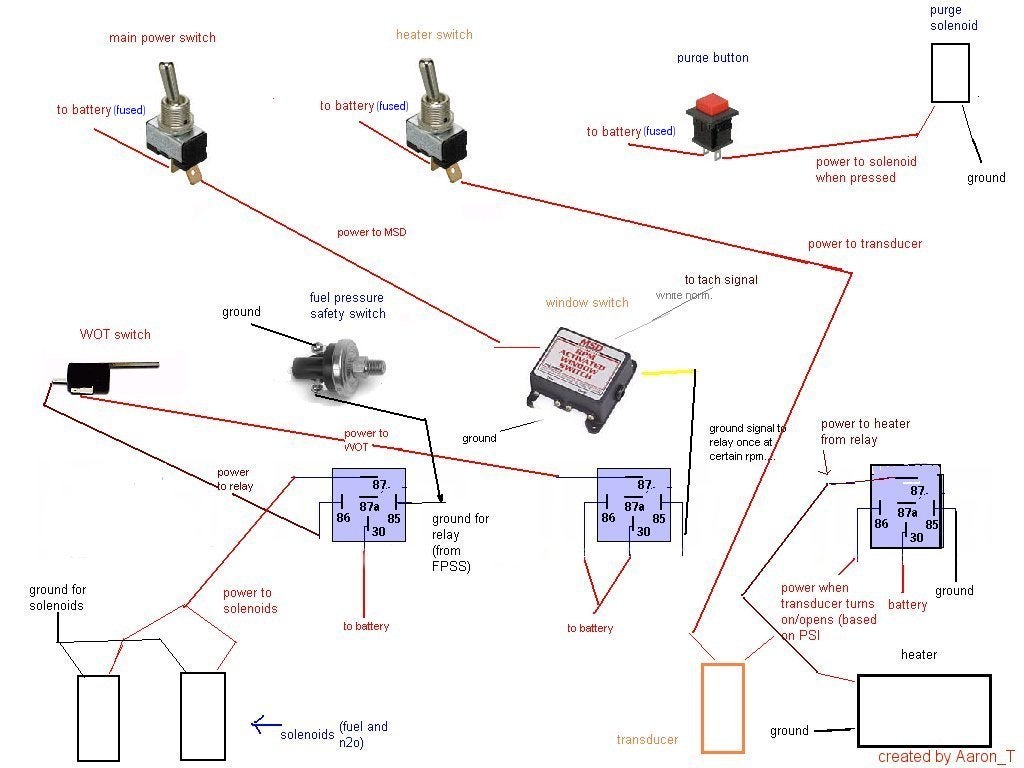
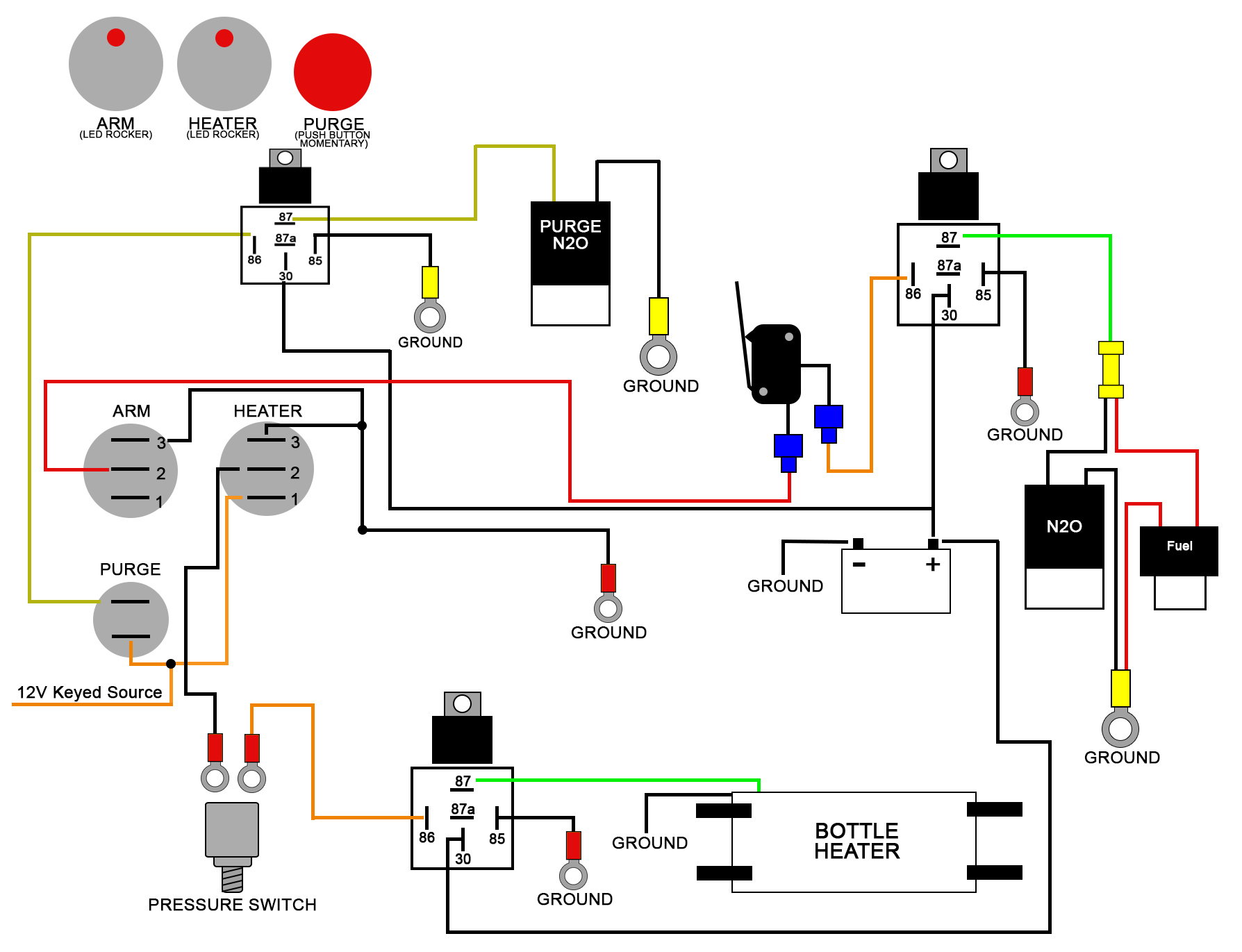
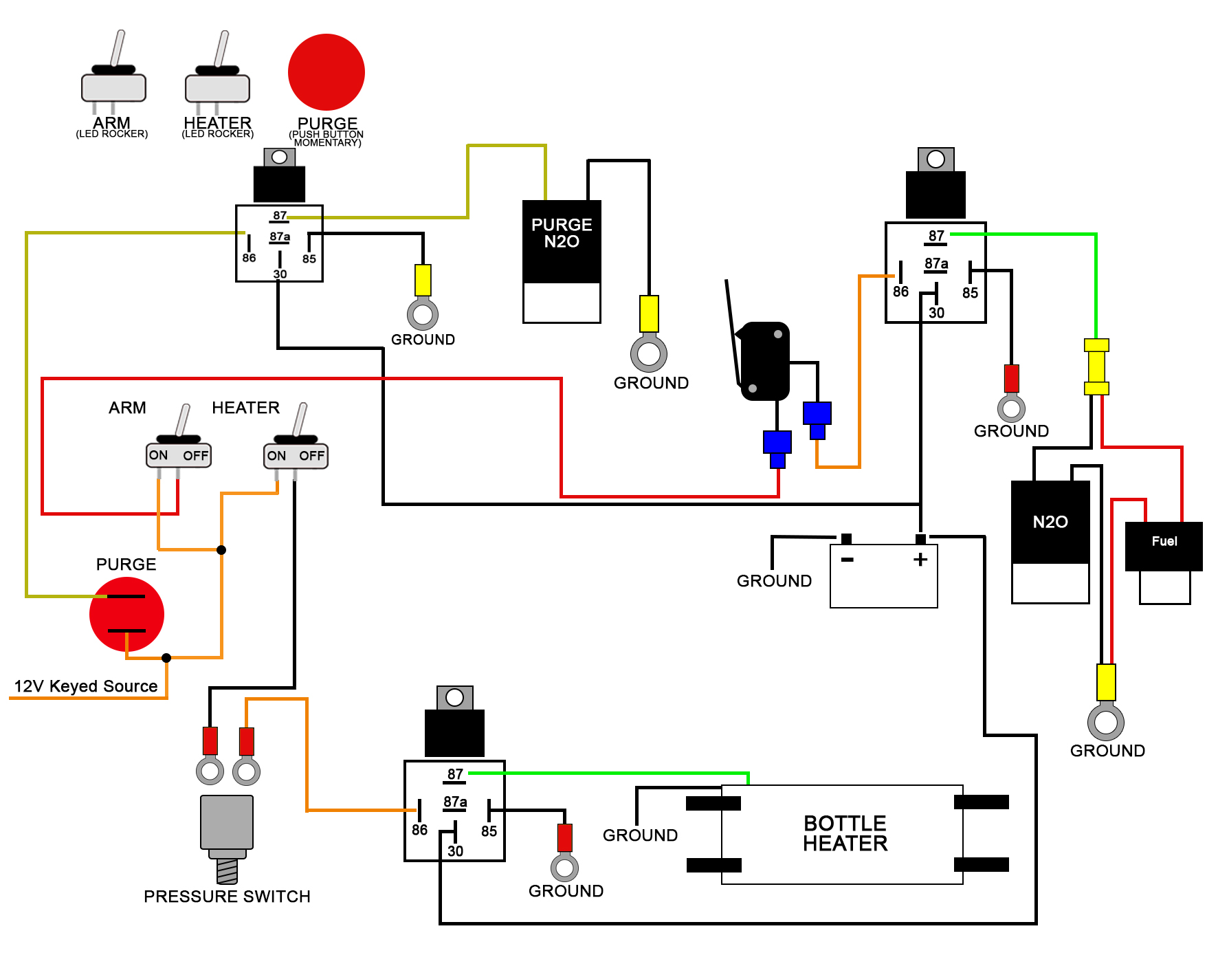
These Wiring Diagrams will help you wire up your Nitrous System or Nitrous Accessory. Includes Nitrous Purge, Nitrous Bottle Heater, and Dedicated Fuel System. Your #1 Source for everything Nitrous. Dealer Locator Account. Toggle navigation 254-848-4300 Speak with a Nitrous Expert M-F 8:30am - 5:30pm CST Call or Text Today! ...
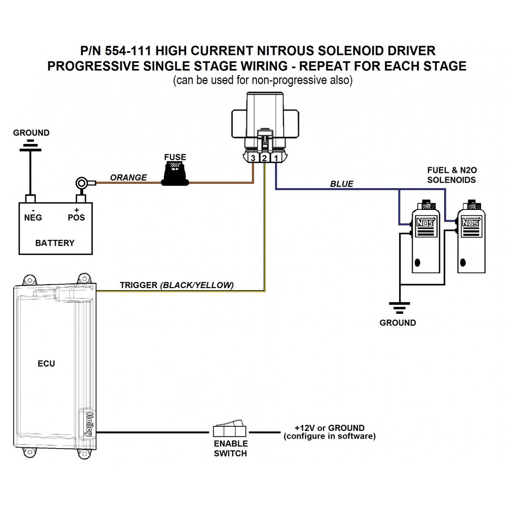
High Current Driver - Module. UPC. 090127666319. Part Number. 554-111. 3. This part is legal for sale and use on Uncontrolled (Non-Emissions Controlled) Vehicles and Racing Use Only Vehicles. The following vehicles are considered Uncontrolled (Non-Emissions Controlled) Vehicles: 1965 and older U.S. manufactured California Certified vehicles.
Nitrous relay wiring diagram.
wire labels. Wire should be stripped back 3/16-1/4 inch. No bare wire should be visible outside the terminal block. Use a miniature Phillips or flat screwdriver to tighten the screws. 5. Solenoid connections. Relays with a minimum 40 amp rating are required. If your nitrous system uses large solenoid valves, you should use the
outstanding nitrous express wiring diagram gallery best image of nitrous express wiring diagram 1 in nitrous express wiring diagram, nx 4 valve mustang plate.Read the tech article on Wiring Electrical Relays Into A Nitrous System, brought to you by the experts at Chevy High Performance Magazine.
Transbrake Nitrous Wiring Diagram. Nitrous system wiring diagrams dragstuff transbrake linelock 2step ls1tech camaro and firebird forum discussion double throw 60 amp relay pn 15515 the pole can be to control a number of diffe accessories nos trans brake express manualzz leash single stage board with interrupt ssnb holley performance products ...
Snowmobile nitrous kits are the best way to make big power! More affordable than boondockers or bossnoss. Nitrous Oxide Kits Systems and components are the quickest and easiest way to get large horsepower increases with a minimum of engine modifications and expense. Nitrous Kits offer serious horsepower at the flip of a switch.
D2f3 Nos Nitrous Relay Wiring Diagram Wiring Resources Https Cdn Shopify Com S Files 1 0890 6136 Files Heater Pdf Bagikan Artikel ini. Belum ada Komentar untuk "Wiring Diagram For Nitrou" Posting Komentar. Catatan: Hanya anggota dari blog ini yang dapat mengirim komentar.
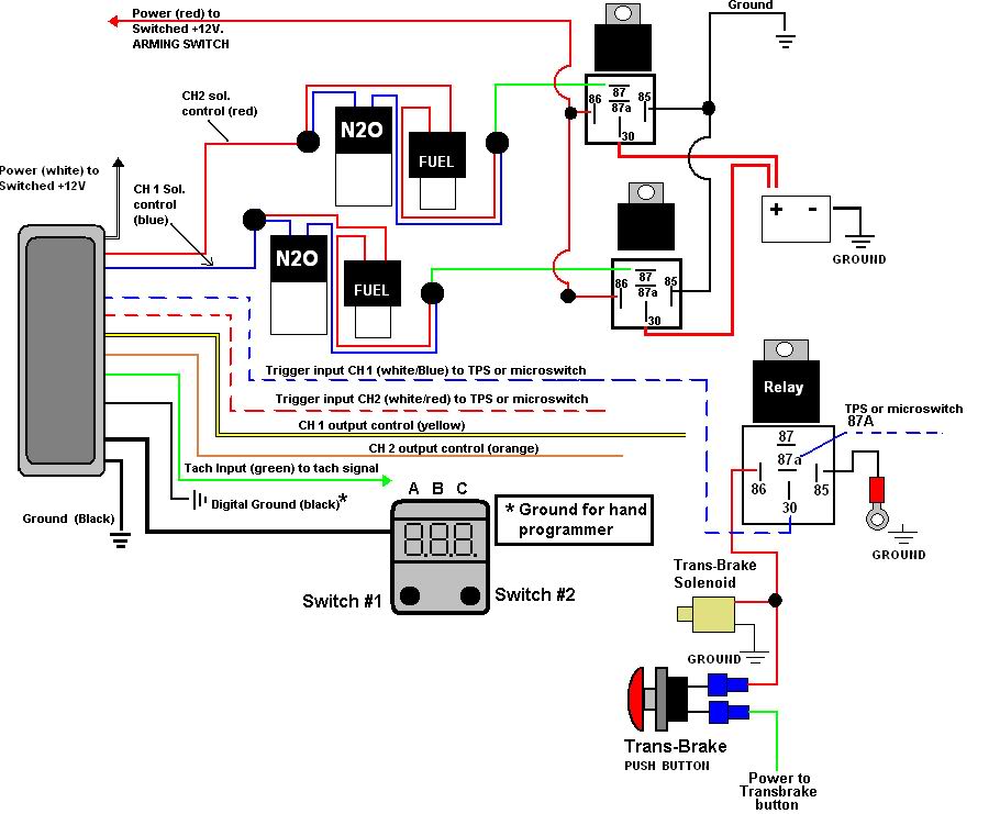
Nitrous Express Maximizer 2 User Manual Page 3 20 Original Mode. Untitled nitrous express maximizer 5 relay panel read all instructions before beginning 4 user manual help 16008 nxs16008s related wiring page 15 ez progressive tested nx rev a 2 15957 harness lnc 2000 and trick controller 16 transbrake nos winmax lingenfelter launch carburetor plate 16006 window switch ii leash single stage ...
wiring diagram from your original instructions. Use only the diagram shown in this instruction booklet. The NOS power relay is designed to prevent high amperage current from damaging the control components, such as switches, microswitches, shift handle buttons, etc. The power contacts in the relay will carry a maximum of 30 amps. MOUNTING:
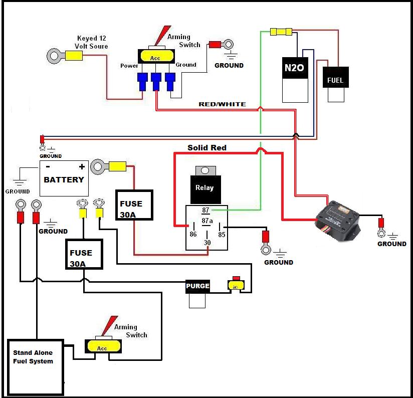
duty relay. (See wiring diagram). 8. Attach the white wire of the relay to ground. If using an optional fuel safety switch connect the switch.
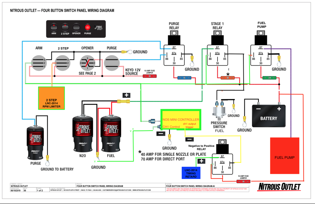
The activation trigger is typically connected to your Nitrous System Throttle Switch, so choice if that is a positive or negative circuit. See wiring diagrams for an example. Ground Trigger is often used for EFI systems or more advanced Nitrous Progressive Controllers like the NMS1000 or AMS-2000 use the ground triggered method.
existing NX relay and plug the Max EZ male plug into your NX relay harness. If your nitrous system does not have a standard NX relay harness, use the included NX relay harness to complete the installation. The following diagrams show installation with popular accessories. Select the appropriate diagram
4,950 Posts. #6 · Dec 23, 2005. If you get no where with this PM me, I have a diagram get me your email and I will send it out or if you tell me every componet for the nitrous your running I can custom build a diagram for yor application. progressive, trans brake, retard module Etc. Or post this In the Electrical section Sparky will take care ...
Board Only Weighs 1.18 lbs. Circuit LED status lights. Positive or Ground Activation on each circuit. 9.75″ Wide x 5.15″ tall. All Relays Replaceable. Uses Standard ATO style fuses. This easy to install high performance racing relay center features Five 40 amp and Five 20 amp relay circuits to make your race car wiring project much easier ...
Relay, figure d, figure c 3 | nitrous express mainline nitrous ...
Mainboard Installation Schematic. 1 Stage Nitrous Using 12 Relay Controller. Nitrous Controller Instructions. 4 Stage Instructions Generic for All Controllers. 4 Stage Nitrous Controller with Main Board and Auxiliary Module Installation Schematic. 3 Stage Nitrous Controller (2 Timed, 1 Instant) with Main Board and Auxiliary Module Installation ...
Nos window switch wiring - camaro5 chevy camaro forum / camaro zl1 ...
relay. If someone would share the wiring diagram, it would be great. I would like to use my transbrake & bump box for staging. 2 that are normal, and one Holley "Nitrous Driver" (which is a solid state relay) for PWM.
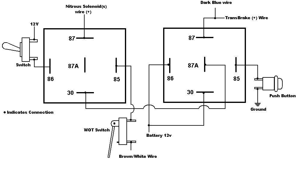
Nitrous relay wiring (multistage)
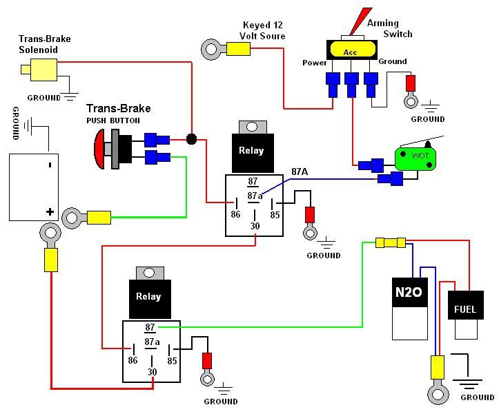
Nitrous Wiring Diagram With Transbrake. The stud labeled "2" is for the transbrake. It is activated by applying +12volts. If you have any questions, email [email protected] or call When wired in series with your nitrous system relay it will enable you plished by splicing into the trans brake solenoid wiring and using this power source to.
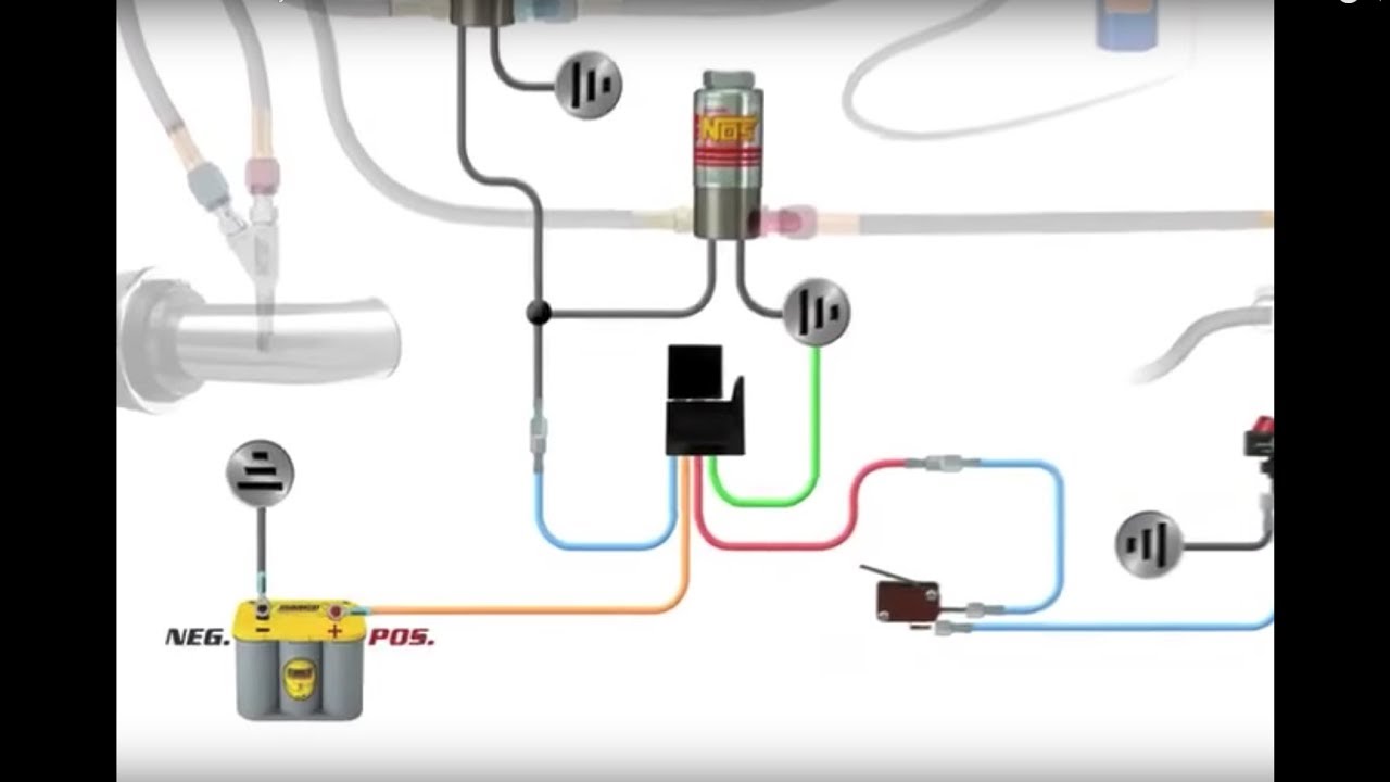
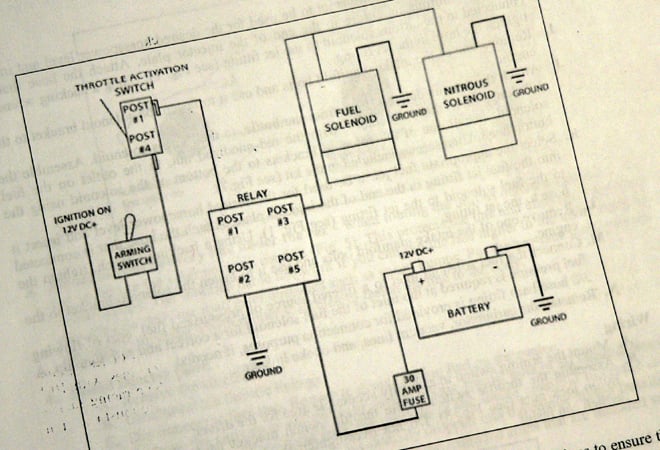
How to wire an nos nitrous system
Nitrous Wiring Diagrams. by John Heard Last Updated Jan 4, 2015. Single Stage NOS System with Transbrake Interrupt Relay. Single Stage NOS System with Transbrake Interrupt Relay, MSD Window Switch, and Dynotune Delay Timer. Single Stage NOS System with Transbrake Interrupt (No Relay), MSD Window Switch, and Dynotune Delay Timer. Single Stage ...
Nitrous wiring? | nitrous | hayabusa owners group
Hi there, I have a question about how to wire up a nitrous system. These are the parts I have. Ford MSD Distributor 8582, RPM Window Switch 8956, MSD 3-Stage Retard Control 8970, MSD High Current Relay 8960 and I want to run this all to a Nitrous System with 100-150 shot. I am also running a 3 Step but I use that for my linelock and trans brake.
Wet kit wiring diagram | tccoa forums
When wired in series with your nitrous system relay it will enable you plished by splicing into the trans brake solenoid wiring and using this power source to. Mar 29, Nitrous Oxide - wiring diagram of 2 step, NOS throttle switch and I need to 2 step and transbrake at rpm or so and have my NOS. Wiring your nitrous kit has NEVER been so easy!

How to install a nitrous express nitrous kit - plate system on ...
NITROUS RELAY BOARDS Designed to work hand in hand with our Delay Boxes. Digital Delay's line of Nitrous Relay Boards are designed to work hand in hand with our Delay Boxes to simplify wiring. All versions of our Nitrous Relay Boards have fused outputs, status indicators, and additional inputs for the Wide Open Throttle Switch and an Override ...
Need a wiring diagram | page 4 | yellow bullet forums
WIRING DIAGRAM FOR 2 STAGE N 2 O WITH TRANSBRAKE NOS P/N 15838 30 NOTES: 1) Bottom view of all relays 2) All relays must be diode suppressed N1~N 2O N/C N/O COM TRIG GND 12 Volt from 87A 85 Transbrake Battery Ground 86 87 30 86 87 87A 85 Battery Ground Battery Positive Fused 20A ...
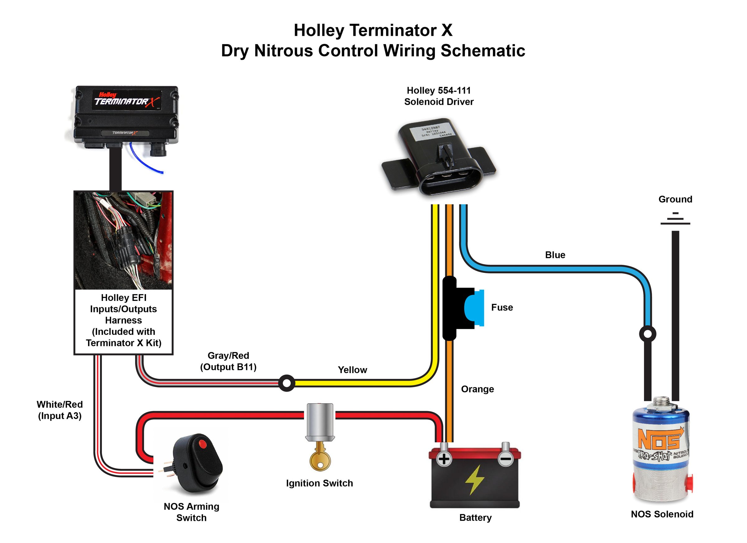
How to set up a terminator x efi system to run nitrous on a ...
nitrous outlet project: opener wiring diagram filename: opener wiring diagram.ai created date: 08/14/2020 pages: contact information: 2 of 2 rev #: 02 opener arm heater opener purge 87 87a 86 30 85 87 87a 86 30 85 opener relay 1 open close opener relay 2 opener 1 ground battery anel 3 2 2 1 10 amp fuse jumper 10 12 ga 12 ga 10 ga 16 ga 16 ga 16 ...
Nitrous oxide installation - zex perimeter nitrous kit - page 2 ...
power all devices being switched ON by the relay. 6. Connect the remaining Blue wire to the device, such as nitrous and fuel solenoids, you wish to turn ON with the relay. 7. It is advisable to connect an in-line fuse holder, or circuit breaker between the relay and the power source of a suitable capacity to protect the relay

Nitrous express maximizer 5 relay panel - pronitrous.com
Nitrous Oxide Install instructions / directions. Step by step pictures and diagrams to help you install your nitrous kit.Systems and components are the quickest and easiest way to get large horsepower increases with a minimum of engine modifications and expense. Nitrous Kits offer serious horsepower at the flip of a switch.
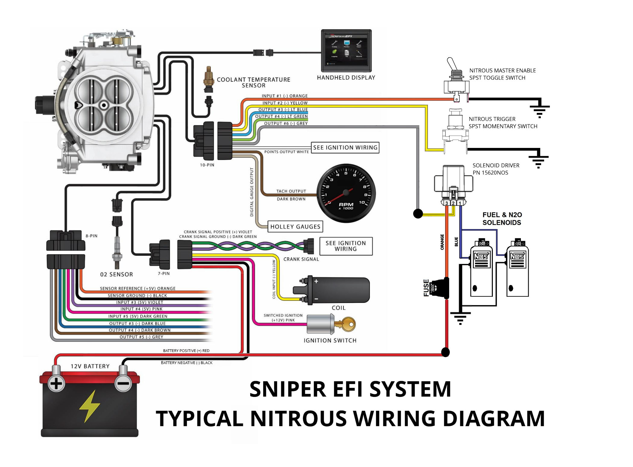
Configuring and wiring sniper efi system for nitrous oxide
Title: wiring diagram Model (1) Author: Dave Created Date: 5/31/2010 9:38:19 PM
Nitrous install wiring help - corvetteforum - chevrolet corvette ...
Nitrous Pressure Gauge and Bottle Heater Controller . Part # 15531 (new style) There are two display modes, normal mode, and programming mode. Normal mode: The display will show the current pressure reading from the pressure sensor. When the bottle heater control is armed, it will turn the heater relay on when below the target pressure and off when

Trans-brake - nitrous express | manualzz
Solenoid. Battery Ground. WIRING DIAGRAM FOR SINGLE STAGE N2 ... SUPPRESSED. RELAY #2. NOS P/N 15640. Optional. Fuel Safety. Switch. Momentary Push. Button.1 page

Leash electronics single stage nitrous board
The NOS Launcher Progressive Nitrous Controller is a fully featured progressive nitrous controller offering control of up to 4 individual stages . These features make this the most advanced nitrous control system on the market. A master controller controls two stages and an additional add-on slave controller can control up to two more stages.
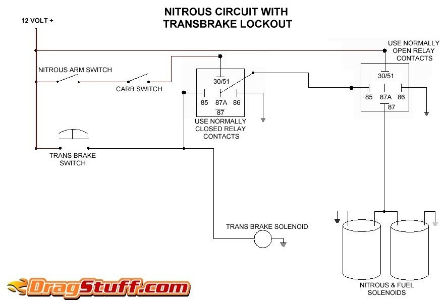
Nitrous system wiring diagrams - dragstuff
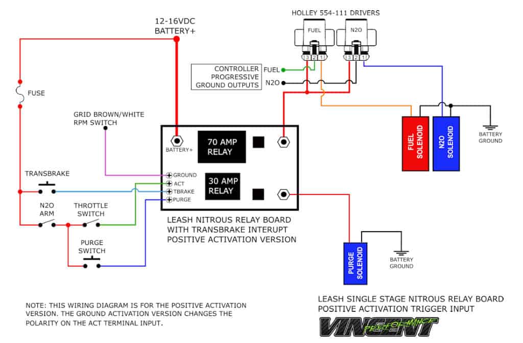
Leash single stage nitrous relay board with transbrake interrupt ssnb
2 step nitrous latching relay 7531 - holley motor life
Nitrous oxide system installation help | cold fusion nitrous
Nitrous oxide system installation help | cold fusion nitrous
Nos 15620nos solid state relay | ships free at efisystempro.com
Nitrous wiring diagram - camaro forums - chevy camaro enthusiast forum

Nitrous kit wiring | ford mustang forums
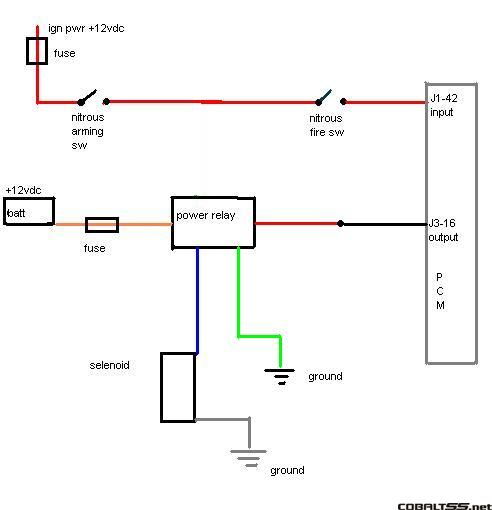
Stage 3 pcm nitrous wiring diagram - cobalt ss network

Help!! install power relay wires and dry nitrous | acura rsx, ilx ...
Nitrous oxide wet kit wiring diagram
Nitrous related wiring - page 15 - ls1tech - camaro and firebird ...
Nitrous install wiring... | stangnet

Aux output problem with nitrous - vipec v series - link engine ...
S300 nitrous relay wireing help prolly over thinking this probelm ...
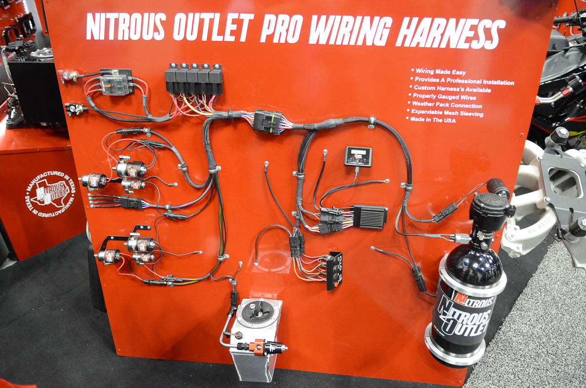
Pri 2015: nitrous outlet simplifies install with new wiring harness
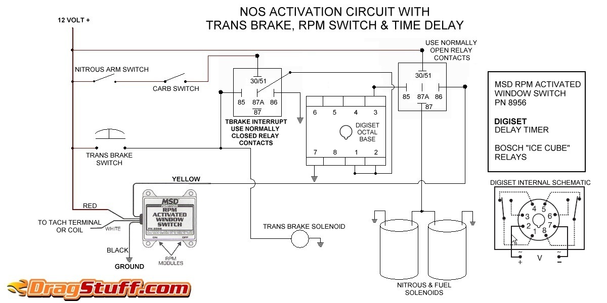
Nitrous system wiring diagrams - dragstuff
Wiring help for my nitrous kit - corvetteforum - chevrolet ...
Wiring window switch to nitrous kit - ls1tech - camaro and ...
Update: installed full nitrous set up and did first test hits ...
How does this wiring setup look? - ls1tech - camaro and firebird ...
Nitrous purge not working | page 3 | dodge srt forum
0 Response to "38 nitrous relay wiring diagram"
Post a Comment