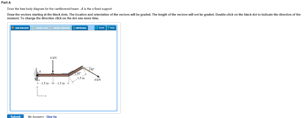
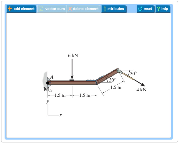
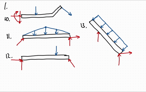
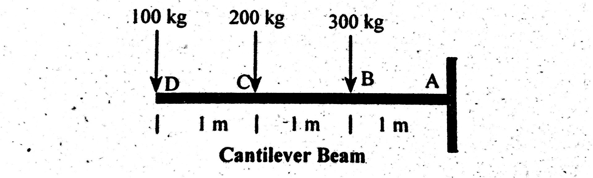
38 draw the free-body diagram for the cantilevered beam. a is the a fixed support.
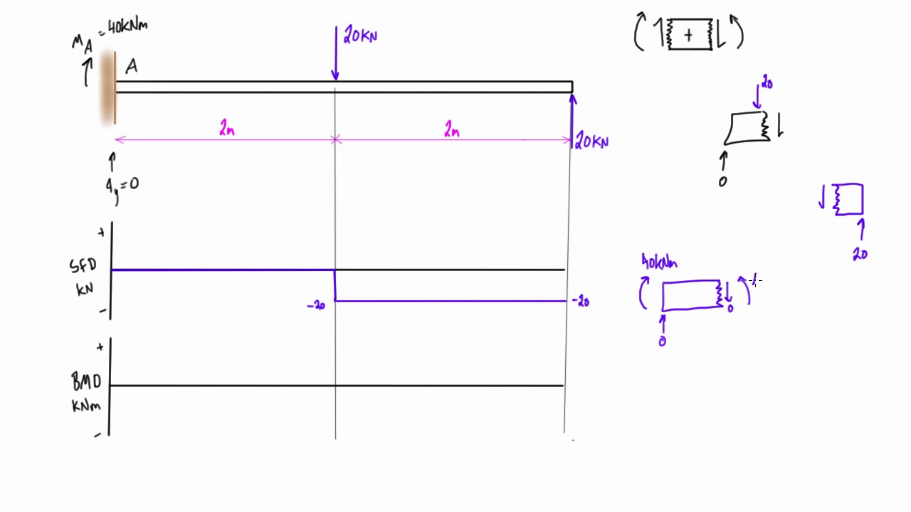
Libro de diseño de máquinas de Shigley. Enter the email address you signed up with and we'll email you a reset link. Show me the final answer↓. Our first step is to draw a free body diagram like so: Remember that since the beam is attached at a fixed support, a moment is also created at A. Let us now write an equilibrium equation for the x-axis forces. → + Σ F x = 0; \rightarrow^+ \Sigma F_x=0; →+ ΣF x. .
Draw the Shear Force Diagram. bending and shear stresses for the beam SKN 10KN/m 12 KN/m B + Im 3m 2m 3m… 1] Draw the shear force and bending moment diagrams for the beam shown below. RB = 13. 1 Beam shear force and bending moment sign convention Where distributed load acts downward on the beam; internal shear force causes aBeams. 100 kN 100 kN/m 60 For …

Draw the free-body diagram for the cantilevered beam. a is the a fixed support.
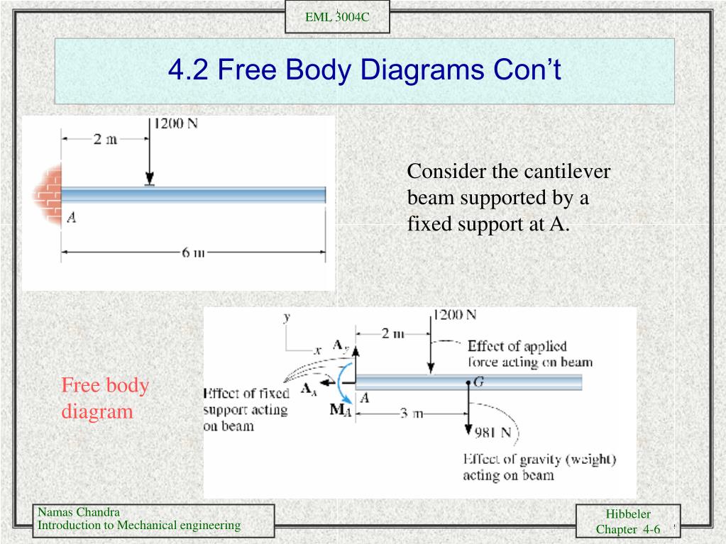
FREE-BODY DIAGRAMS (Section 5.2) 2. Show all the external forces and couple moments. These typically include: a) applied loads, b) support reactions, and, c) the weight of the body. Idealized model Free-body diagram (FBD) 1. Draw an outlined shape. Imagine the body to be isolated or cut "free" from its constraints and draw its outlined shape. 4.4 Moment Diagrams by Parts The moment-area method of finding the deflection of a beam will demand the accurate computation of the area of a moment diagram, as well as the moment of such area about any axis. To pave its way, this section will deal on how to draw moment diagrams by parts and to calculate the moment of such diagrams about 05.03.2021 · Free-body diagram. The free-body diagram of the beam is shown in Figure 4.10a. Support reactions. The reactions at the support of the beam can be computed as follows when considering the free-body diagram and using the equations of equilibrium: Shearing force and bending moment functions of beam BC. 0 < x 1 < 3. V = 0. M = 0. 3 < x 2 < 6. V ...
Draw the free-body diagram for the cantilevered beam. a is the a fixed support.. Transcribed image text: Draw the free-body diagram for the cantilevered beam. A is the a fixed support. Draw the vectors starting at the black dots. The location and orientation of the vectors will be graded. The length of the vectors will not be graded. Double-click on the back dot to indicate the direction of the moment. AMERICAN FOREST & PAPER ASSOCIATION Figures 1 through 32 provide a series of shear and moment diagrams with accompanying formulas for design of beams under various static loading Possible free-body diagrams for two common situations are shown in the next two examples. Example 5.2.5. Fixed support. The cantilevered beam is embedded into a fixed vertical wall at A. Draw a neat, labeled, correct free-body diagram of the beam and identify the knowns and the unknowns. Solution. beam diagrams and formulas 3-213 table 3-23 shears, moments and deflections 1. simple beam-uniformly distributed load ... cantilevered beam- load increasing uniformly to fixed end ... beam fixed at one end, free to deflect vertically but not rotate at other - uniformly distributed load total equlv. uniform load .....
Fixed support. The cantilevered beam is embedded into a fixed vertical wall at \(A\text{.}\) Draw a neat, labeled, correct free-body diagram of the beam and identify the knowns and the unknowns. Solution. Begin by drawing a neat rectangle to represent the beam disconnected from its supports, then add all the known forces and couple-moments. Label the magnitudes of the … beam diagrams and formulas by waterman 55 1. simple beam-uniformly distributed load ... 22. cantilever beam-concentrated load at free end. 23. beam fixed at one end, free to deflect vertically but not rotate at other-concentrated load at deflected end 24. beam overhanging one support-uniformly distributed load. 25. beam overhanging one support ... Part A Draw the free-body diagram for the cantilevered beam. A is the a fixed support. Draw the vectors starting at the black dots. The location and orientation of the vectors will be graded. The length of the vectors will not be graded. Double-click on the black dot to indicate the direction of the moment. Example 6: For the cantilever beam and loading shown, determine the reactions at the support. Solution: We begin our analysis by first drawing the free-body diagram of the beam. Once we have the unknown reaction loads identified, we solve for them using the equilibrium equations.
Determine the components of the support reactions at the fixed support A on the cantilevered beam. Solution: Show me the […] Determine the components of the support reactions. August 8, 2018 in Mechanics: Statics tagged Engineering Mechanics: Statics / equilibrium . 2 . 19.11.2021 · E,I Mo Problem 1. (a) Draw the free body diagram (FBD) of the entire beam and calculate the reactions at A. Figure 1. The beam shown in Fig. You either need to have fixed support or have a back span and check for the uplift of the far support. 4. 1 Problem Statement and Objectives It is required to determine the natural frequencies and mode ... Free body diagrams may not seem necessary in the relatively simple current applications, but as problems become more complex, their usefulness increases. The following is the process for determining the reaction at the wall for a cantilever beam. Part A Draw the free-body diagram for the cantilevered beam. Subject: Civil Engineering Price: 3.85 Bought 3. Share With. Part A Draw the free-body diagram for the cantilevered beam. A is the a fixed support. Draw the vectors starting at the black dots. The location and orientation of the vectors will be graded. The length of the vectors will ...
In this article Learn :cantilever beam Bending moment diagram B.M.D. and shear force diagram S.F.D. of a cantilever beam having point load at the end,several point loads,U.D.L. Over Whole Span ,U.D.L. not over the whole span,U.D.L. from support to some distance,U.D.L. Somewhere on the beam,Combination of Point Loads and U.D.L.
1. Draw Free Body Diagram 2. Apply Equilibrium Example: Cantilevered Flag Figure M4.3-8 Geometry and free body diagram of cantilevered flag z x ~ ~ ~ • x z m = mass/unit length mg H A V A M A f f L L FREE BODY DIAGRAM:
Draw the vectors starting at the black dots. Our first step is to draw a free body diagram like so. Determine the components of the support reactions at the fixed support a on the cantilevered beam. A y 4knd 0 m a. The cantilever is a beam which has one end free and the other is fixed.

Determine the components of the support reactions at the fixed support A on the cantilevered beam. Determine the components of the support reactions at the fixed support A on the cantilevered beam.
22.11.2021 · The free-body diagram of the entire beam is shown in Figure 3. A resultant force is the force (magnitude and direction) obtained when two or more forces are combined (i. Determine the resultant force and specify where it acts on the beam measured from A . F 3 = -30 N. Jul 19, 2017 · The beam is loaded with constant line loads between B and C, and between D and H, …
Sketch the beam diagrams and determine the location on the beam where the bending moment is zero. Problem 4: A simple overhanging beam 112 ft long overhangs the left support by 14 ft. The beam carries a concentrated load of 90 kips 12 ft from the right end and a uniform distributed load of 12 kips/ft over a 40 ft section from the left end.

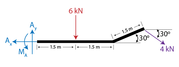
• Create a free-body diagram for the complete frame and solve for the support reactions. • Define a free-body diagram for member BCD. The force exerted by the link DE has a known line of action but unknown magnitude. It is determined by summing moments about C. • With the force on the link DE known, the sum of forces in the x and y directions
directly on the diagram. Pertinent dimensions may also be represented for convenience. Note, however, that the free-body diagram serves the purpose of focusing accurate attention on the action of the external forces; therefore, the diagram should not be cluttered with excessive information. Force arrows

Draw free-body-diagram (FBD) 2. The site selected was adjacent to the ford near the Tharwa settlement and required a total length of bridge of about 600 feet. HideClick here to read or hide the general instruction Write shear and moment equations for the beams in the following problems. 2 N/mm2 (This is clear if we make the bending moment diagram for the beam, in …
Any changes made will automatically re-draw the free body diagram any simply supported or cantilever beam. The beam reaction calculator and Bending Moment Calculations will be run once the "Solve" button is hit and will automatically generate the Shear and Bending Moment Diagrams.
A truss is supported with a pin and two roller supports as shown in figure 3
Draw the Free Body Diagrams. Learning Objectives 1. To be able to explain the equilibrium of Rigid Body Systems ... A Cantilever has to be fixed to support a load. Question 1. What is the difference between a Rigid Body and a Particle Question 2: Explain the Difference between a ... Beam Free Body Diagram. Actual Structure - A Truss Free Body ...
Using the free-body diagram of the portion AC of the beam (Fig. 8.8), where C is located at a distance x from end A, we find (8.7) Substituting for M into Eq.. (8.4) and multiplying both members by the constant El, we write d 29' El Integrating in F, we obtain The deflection and slope at A are obtained by letting — O in Eqs. (8.11) and (8.9).
Classify the beams shown in Figure 3.1 through Figure 3.5 as stable, determinate, or indeterminate, and state the degree of indeterminacy where necessary.. Fig. 3.1. Beam. Solution. First, draw the free-body diagram of each beam. To determine the classification, apply equation 3.3 or equation 3.4.. Using equation 3.3, r = 7, m = 2, c = 0, j = 3. Applying the equation leads to 3(2) + 7 > 3(3 ...

06.10.2012 · For a cantilevered beam (with one end embedded or rigidly fixed at the wall), the wall may exert horizontal and vertical forces and an external torque (which we will call an external moment, and label M ext) acting on the beam – as we have shown in the free body diagram of the beam. STEP 1: Draw a free body diagram showing and labeling all ...
fixed-connected collar Two unknowns. The reactions are two force components. Fy Fx Type of Connection Idealized Symbol Reaction Number of Unknowns F M Two unknowns. The reactions are a force and moment. Three unknowns. The reactions are the moment and the two force components. M Fy Fx (7) fixed support (5) Smooth pin or hinge (6) slider
https://goo.gl/P5AUbb for more FREE video tutorials covering Engineering Mechanics (Statics & Dynamics)The key objective of this video is to consider support...
A is the a fixed support. Draw the free body diagram fbd of the uniform cantilever beam shown. Help with free body diagram feb 3 2013 1. Draw the free body diagram for the cantilevered beam. If a beam is cantilevered it has a fixed support at one end which is the right end for this beam the beam weighs 150 lbft and the weight of the beam acts ...
(which has an overhang) and a beam fixed (or restrained) at both ends, respectively. Cantilever beams and simple beams have two reactions (two forces or one force and a couple) and these reactions can be obtained from a free-body diagram of the beam by applying the equations of equilibrium. Such beams are said to be statically
19.05.2018 · Draw the shear and moment diagrams for the cantilevered beam. 300 lb 200 lb/ft A 6 ft The free-body diagram of the beam’s left segment sectioned through an arbitrary point shown in Fig. b will be used to write the shear and moment equations. The intensity of the triangular distributed load at the point of sectioning is Referring to Fig. b, w = 200a x 6 b = …

Draw free body diagram for the segment of the beam. Show S & M at the cut section, 5. Write the equilibrium equations, obtainable from the free body diagram, 6. Solve the equilibrium equations for the Shear Force S and the Bending Moment M, 7. Plot the expressions for S and M for the segment. It is desirable to draw the shear force diagram ...
05.03.2021 · Free-body diagram. The free-body diagram of the beam is shown in Figure 4.10a. Support reactions. The reactions at the support of the beam can be computed as follows when considering the free-body diagram and using the equations of equilibrium: Shearing force and bending moment functions of beam BC. 0 < x 1 < 3. V = 0. M = 0. 3 < x 2 < 6. V ...
4.4 Moment Diagrams by Parts The moment-area method of finding the deflection of a beam will demand the accurate computation of the area of a moment diagram, as well as the moment of such area about any axis. To pave its way, this section will deal on how to draw moment diagrams by parts and to calculate the moment of such diagrams about
FREE-BODY DIAGRAMS (Section 5.2) 2. Show all the external forces and couple moments. These typically include: a) applied loads, b) support reactions, and, c) the weight of the body. Idealized model Free-body diagram (FBD) 1. Draw an outlined shape. Imagine the body to be isolated or cut "free" from its constraints and draw its outlined shape.


0 Response to "38 draw the free-body diagram for the cantilevered beam. a is the a fixed support."
Post a Comment