37 universal fuel gauge wiring diagram
July 23, 2021 by. View Universal Fuel Gauge Wiring Diagram. Pics. Gauges will require minor wiring revisions. However, if it's inevitable, use universal symbol to indicate if there's a intersection or if the lines aren't actually connected. Audi Fuel Gauge Wiring Wiring Diagrams Name Seek Function Seek Function Illabirintodellacreativita It ... Daniel grill/getty images if your gas gauge has been acting up, o…. Read more. Fuel Sending Unit Wiring Diagram : 0-90 Ohms Fuel Gauge - Fuel Cell Sending Unit - Fuel Sender. November 25, 2021.
The wiring diagrams below come from 1 original owners manuals 2 service manuals 3 supplement sheets 4 parts manuals 5 actual mopeds wirings or parts new or used or most often 6 a combination of most of those. 17 Universal Motorcycle Speedometer Wiring Diagram Motorcycle Diagram Wiringg Net Types Of Electrical Wiring Diagram Autometer Gauges.

Universal fuel gauge wiring diagram
A wiring diagram is a type of schematic which makes use of abstract pictorial signs to show all the interconnections of components in a system. Case Starter Wiring Diagram. What is a Wiring Diagram. Signs that stand for the parts in the circuit as well as lines that represent the connections in between them. The Case IH CX50 CX60 CX70 CX80 CX90 ... Making a "Pigtail" to Connect to MegaSquirt. You will need to connect your MegaSquirt ® EFI controller to power, ground, sensors, fuel pump, fast idle valve, and injectors. You can do this using 18 or 20 gauge wires. The ground and injector wires carry more current, however they are "doubled-up" on the board. TH4110U2005/U TH4210U2002/U Wiring Diagrams [pdf]: T4 and T1 PRO Wiring Diagrams Contents hide 1 Specifications 2 Downloads 2.1 Related Manuals Specifications T4 Pro Programmable Thermostat Color White Includes T4 Pro Thermostat, UW Mounting System, Honeywell Home Standard Installation Adapter (J-box adapter), Honeywell Home Decorative Cover Plate, Screws and anchors, 2 AA Batteries ...
Universal fuel gauge wiring diagram. Club Car Wiring Diagram Gas - 1985 gas club car wiring diagram, 1987 gas club car wiring diagram, 2003 gas club car wiring diagram, Every electrical arrangement is composed of various distinct components. Each part should be set and linked to different parts in specific way. If not, the arrangement will not function as it should be. HOT ROD HOLIDAY. Up to $150 Mail-In Rebate Nov 1, 2021 thru Dec 31, 2021 Yamaha 150 outboard wiring diagram trim relay wiring diagram club trim relay wiring diagram trim for mercury 2006 yamaha 150 outboard wiring diagram. Installing a universal fuel sender from veethree elec & marine llce nz and a mercury digital fuel gauge from trademe seller silverdalemarine on my boat. Over the years, Auto Meter has established itself as a manufacturer of quality, professional automotive gauges. Adding any Auto Meter gauge to your vehicle ...
variety of fuel tank shapes, this universal gauge cannot compensate for the different rates that ... 5. route all wiring away from linkages, engine parts.1 page fuel gauge sending unit wiring diagram - You'll need an extensive, skilled, and easy to comprehend Wiring Diagram. With this sort of an illustrative guide, you are going to be able to troubleshoot, prevent, and complete your tasks without difficulty. Instrument Wiring Diagram. Many meters don't work, most of them are due to wrong wiring. If you encounter this problem, please contact us as soon as possible and ask for wiring diagram. I hope you have a happy shopping experienceIf there is a problem with the water temperature gauge or the oil temperature gauge: 1. Check if there is any wiring ... Wire Harness Connectors Kit. angelo. October 29, 2021. 1 Set For Sumitomo 2 Pin Motorcycle Car Female Male Kit Wire Harness Connector Car Electronics Electronic Accessories Harness. 2 Pin 15326801 13510085 Female Male Automotive Connector Kit Gm Wiring Harness Connector 1 5a Plug Plugs Delphi Harness. 11pcs 8pcs 3pcs Car Electrical Wiring Crimp ...
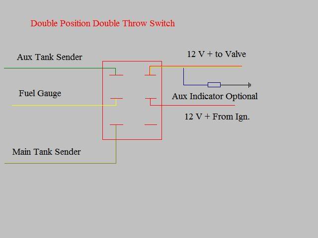
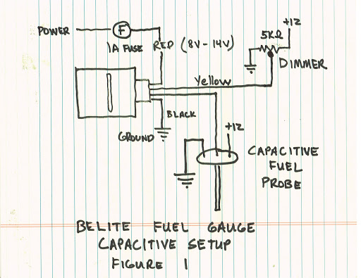
Aug 17, 2016 — Check the wiring diagram that comes with the kit and mark the back of the new fuel gauge with symbols for each post: “S” for the sender, ... Lg wt1101cw manuals and user guides for free. Used the diagram to figure out what to order. Source: f01.justanswer.com. Stator assembly circuit in the main pcb / wiring diagram wiring diagram the dd motor can be driven from stopped to maximum speed in infinite steps in either direction. Source: i.pinimg.com. Lg wt1101cw washer user manual. You may use 18g or 20g stranded wire for all fuel level gauge wiring. S. = This connects to the sending unit in the fuel tank. **(See Sending Unit Wiring ...3 pages Bms wiring diagram. Atv safety action plan. Atv safety action plan. Wiring installation manual document revision 4 1 the orion bms by ewert energy systems is designed to manage and protect lithium ion battery packs and is suitable for use in electric plug in hybrid and hybrid electric vehicles as well as.
Koso North America. KOSO, a synonym for quality and performance has been operating for more than 30 years . Designing and manufacturing high-quality products, KOSO is well known in the motorcycle, snowmobile, ATV and scooter industries. KOSO's good reputation for reliability and innovation capability helped make KOSO a source for many major ...
1973-1977 Monte Carlo Fuel Tank Sending Unit 5/16" Line (2 Outlet - Fuel Sending Unit Wiring Diagram. Wiring diagram also provides useful recommendations for assignments that may demand some additional tools. This book even includes recommendations for added provides that you might require to be able to finish your assignments.
The MaxTow Double Vision® Gauge Series was designed to bring diesel and truck enthusiasts a gauge with the best of both worlds which includes digital and analog gauge readings. The MaxTow Double Vision Gauge Series outperforms the competition by featuring electronic sensors, stepper motor technology, smooth needle movement, a green or blue LED ...
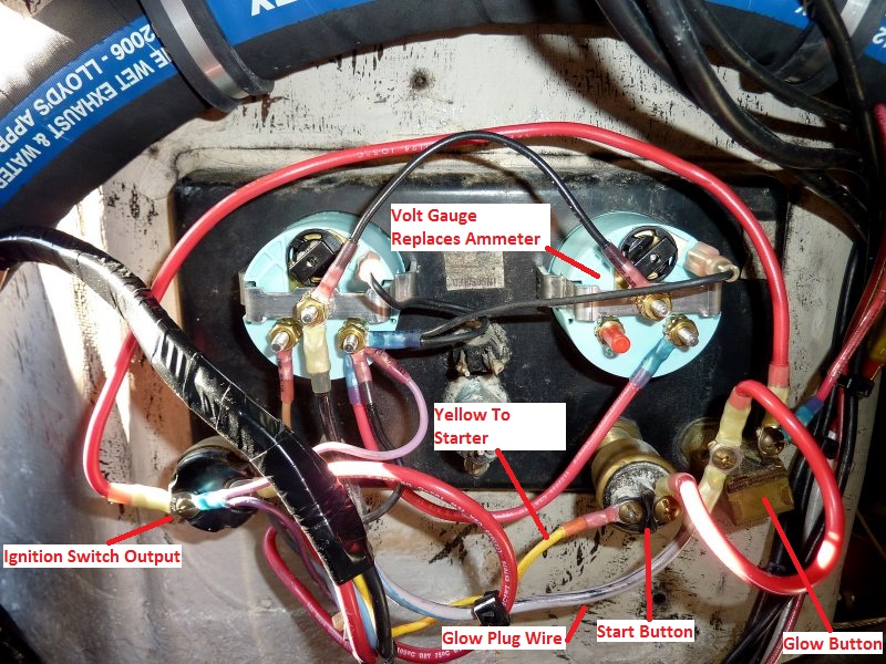
It is always recommended that you label each wire before you remove the old ignition switch. Typical wiring for the JK290A Ignition switch is below, however the existing wiring may vary. Wire labeled 12 (Glow Plugs) goes to Terminal #3 on the ignition switch. Wire 10 (Solenoid/Starter) goes to Terminal #4. Wire 6 (Gauges) goes to Terminal #2.
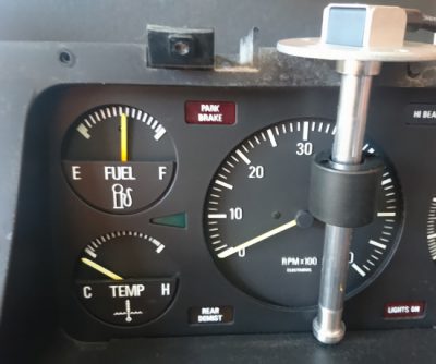
2" 52mm Car Universal Fuel Level Gauge Meter W/ Fuel Sensor E-1/2-F Pointer Set. Report item. - opens in a new window or tab. Description. Shipping and payments. eBay item number: 333425980112. Seller assumes all responsibility for this listing. Last updated on May 28, 2021 01:19:57 PDT View all revisions.
The MAX17330 is a 28μA I Q stand-alone charger, fuel gauge, protector, and battery internal self-discharge detection IC for 1-cell lithium-ion/polymer batteries. When a voltage source is present, the MAX17330 regulates charging by modulating the charge N-FET, using AccuCharge™ charger technology.
Wiring Diagram Caterpillar Ecm Yhgfdmuor Net And Cat 70 Pin On Caterpillar C15 Ecm Wiring Diag Electrical Wiring Diagram Circuit Diagram Trailer Wiring Diagram . 1397 Precision Universal Joint U Joint End Yoke 2 4 533 Listing In The Universal Joints Driveshafts Transmission Drivetrain Universal Joint Joint Universal
The wire gauge used in the 21-circuit Mopar wiring harness varies depending on the circuit. It ranges from 10 to 18 gauge, with the heavier gauge wire generally being used for major components like the starter, alternator, etc., and lighter gauge for things like the instrument panel and interior lights.
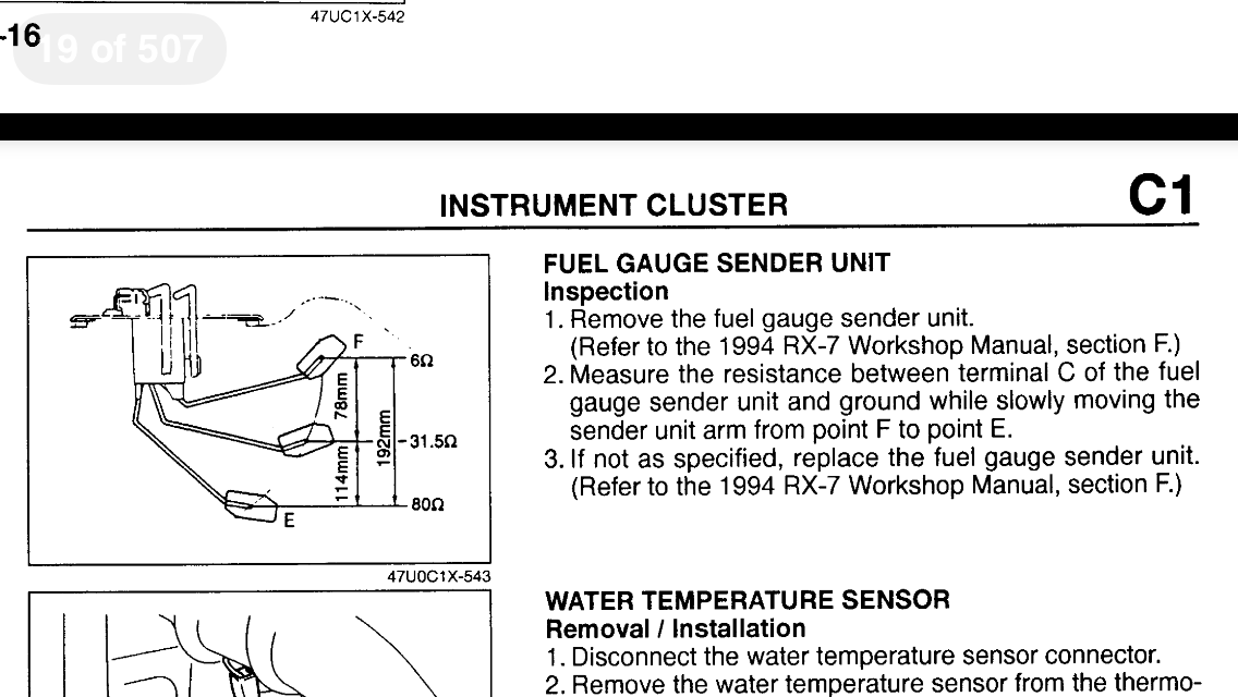
Moeller Marine Swingarm Electrical Fuel Sending Units. Moeller Marine swingarm electrical fuel sending units gather fuel level information from a float, which is then read on a dash-mounted gauge. The units allow you to set the swingarm float to the exact length required for accurate readings from your fuel tank.
The dynamo circuit originally had a standard gauge brown/green (field) wire, and a thicker gauge brown/yellow (output) wire. Because of this it's best to use the thicker brown/yellow wire for the output of the alternator, even though this goes against the convention on cars equipped with an alternator from the factory.
attach fuel line to port on the top of the pump module and extend it to the new pump; attach return line to port and run it to where the new pump is. cut the positive wire in the harness for the old fuel pump and extend it to where the new pump is. tap a wire off of the ground for the old pump and run it to the new pump.
Fuel gauge reading incorrectly does not affect the engine functions or create any major problem.You can drive just fine without damaging any major component. But, not being able to read the correct gas level will result in running out of gas with no warning. The functions of a fuel gauge are to show the amount of fuel in the gas tank and to give a warning when it's time to refuel.
Universal Terminals Bosch Delphi / Packard Deutsch Ford / EPC Furukawa Kostal Sumitomo Tyco / AMP Yazaki COVID 19 Data Logging/Dash Systems Engine Control Forced Induction Fuel Gauges Heat Shrink Ignition Relays / Fuses Sensors Tools Wideband O2 Wiring
1973-1977 Monte Carlo Fuel Tank Sending Unit 5/16" Line (2 Outlet - Fuel Sending Unit Wiring Diagram. Wiring Diagram includes each examples and step-by-step instructions that will enable you to definitely actually develop your undertaking. This can be beneficial for both the folks and for specialists who are seeking to find out more on how ...
Lastly, connect a fused constant power to both of the red wires on the relays. This is the load side of the relay and you should use a minimum of 14 gauge wire here. The white wire on the relay pigtail will not be used. With these dual fans wired up you can keep your car cool and not have to worry about clearance issues!
TH4110U2005/U TH4210U2002/U Wiring Diagrams [pdf]: T4 and T1 PRO Wiring Diagrams Contents hide 1 Specifications 2 Downloads 2.1 Related Manuals Specifications T4 Pro Programmable Thermostat Color White Includes T4 Pro Thermostat, UW Mounting System, Honeywell Home Standard Installation Adapter (J-box adapter), Honeywell Home Decorative Cover Plate, Screws and anchors, 2 AA Batteries ...
Making a "Pigtail" to Connect to MegaSquirt. You will need to connect your MegaSquirt ® EFI controller to power, ground, sensors, fuel pump, fast idle valve, and injectors. You can do this using 18 or 20 gauge wires. The ground and injector wires carry more current, however they are "doubled-up" on the board.
A wiring diagram is a type of schematic which makes use of abstract pictorial signs to show all the interconnections of components in a system. Case Starter Wiring Diagram. What is a Wiring Diagram. Signs that stand for the parts in the circuit as well as lines that represent the connections in between them. The Case IH CX50 CX60 CX70 CX80 CX90 ...







0 Response to "37 universal fuel gauge wiring diagram"
Post a Comment