37 ford 6.0 diesel vacuum line diagram
Fig. 6: 1988-89 (VIN K) R/V series with 5.7L, AT, Calif. Access our GM Full-Size Trucks 1988-1998 Vacuum Diagrams Repair Guide by creating an account or signing into your AutoZone Rewards account. Once you sign in, follow these instructions to access our Repair Guides. Add your vehicle in Manage My Vehicles. Enter your vehicle details.
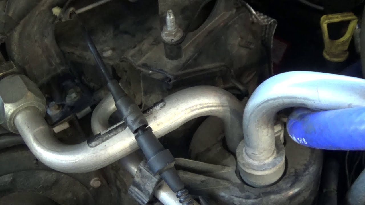
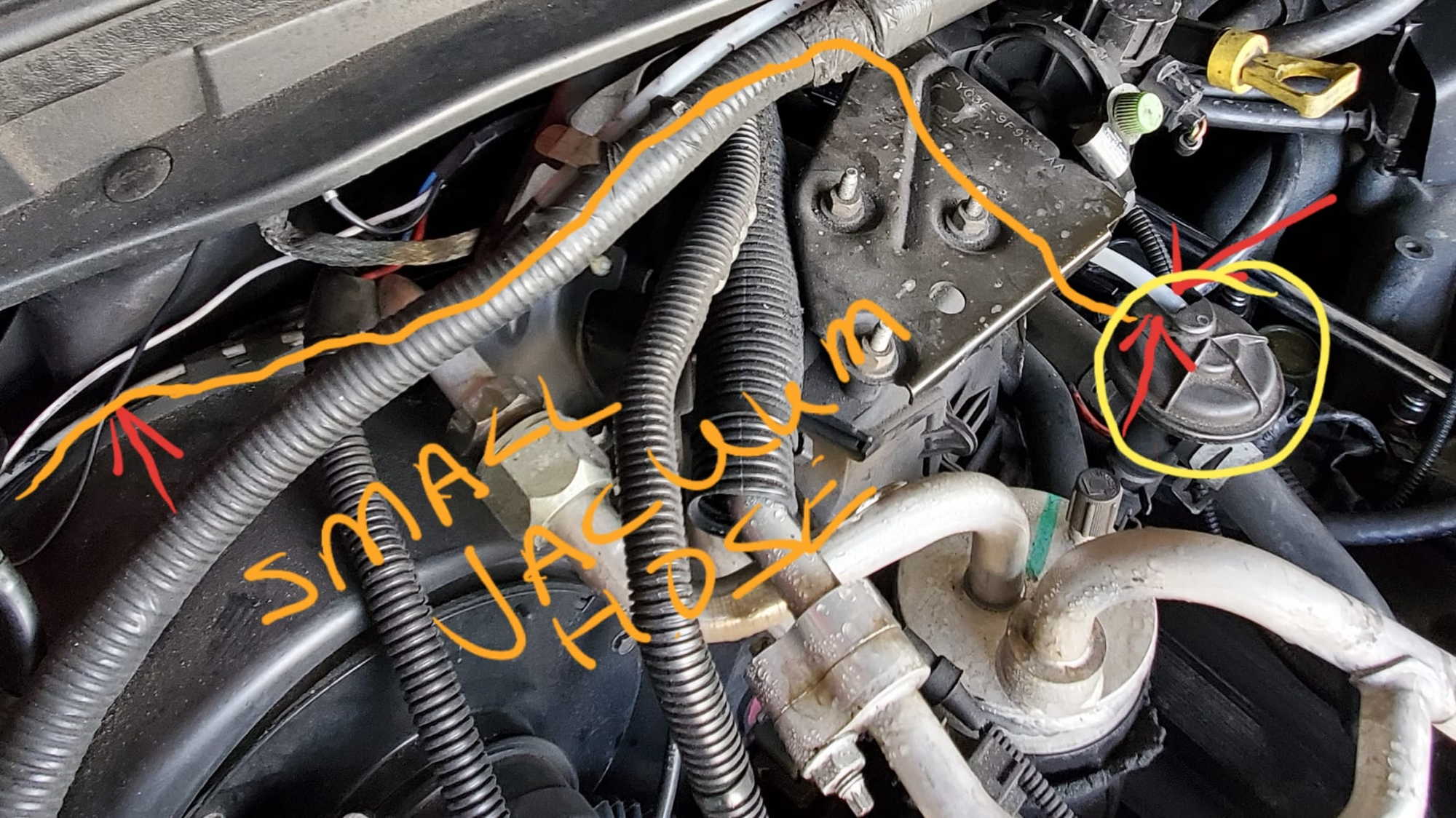
This picture shows the removed broken vacuum line fitting and new fitting I purchased for the repair. The new fitting is a 3/16" vacuum line connector fitting. Press the new fitting into the the vacuum line. Place the tube/fitting through the bracket. Press the hose from the hub on the other end of the vacuum line connector.
Crankshaft Position Sensor 949979-031# 8-97606943-0 Cylinder Recognition Sensor 949979-169# 8-98019024-0 Fuel Pressure Sensor 499000-829# 8-98105928-0 Exhaust Gas Temperature Sen-sor 265600-125# 8-98004329-0 DPF Side Exhaust Gas Temperature Sen-sor 265600-126# 8-98004330-0 SCR Side Differential Pressure Sensor 104990-101# 8-97359985-2

Ford 6.0 diesel vacuum line diagram
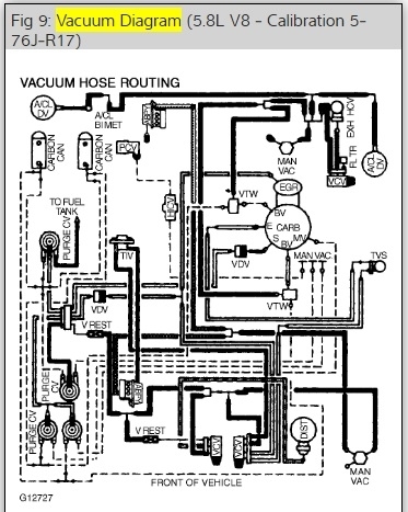
Vacuum Diagrams This is not an automated service. Each Diagram that is requested has to be hand selected and sent. As this is a free service it receives an overwhelming amount of requests and may take up to a week or longer for a response.
Fusion. F-250 Super Duty. Expedition. Focus. Mustang. Other. Shop for Genuine Ford Parts from Ford Parts Center. These Authentic OEM Ford Parts are manufactured to the highest quality standards, and will fit your Ford car or truck perfectly. We offer Original Ford Motor Company Parts, at a price that won't break the bank, right to your door.
diagram does not match the master Car Standard Wire Code Chart. If your vehicle has a color coded wire that does not match a diagram you should consult the other diagrams contained in the manual for a possible match. Example of possible errors. The color coded wiring diagrams are provided for illustration purposes only. Only the wire
Ford 6.0 diesel vacuum line diagram.
Ford Genuine F65Z-19A566-AA A/C Vacuum Reservoir. 4.8 out of 5 stars. 78. $25.88. $25. . 88. Get it as soon as Wed, Nov 10. FREE Shipping by Amazon.
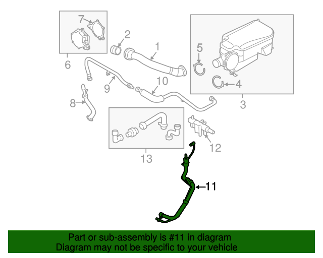
Apr 25, 2015 · Need diagram of the turbo hose location at the top of turbo. Your truck came with a 6.0 and a 7.3 so am not sure what you have or exactly what hoses you are talking about for sure. Below is a diagram of the complete turbo and hoses/ducts for a 7.3. I hope this is what you need and I hope this helps.
Late '99, F-250 7.3L, PSD, Super Duty, AT, 4X4, Crew Cab, 235 Mich tires, MBRP 4" Exhaust, 6-setting DP-Tuner (set for +80hp Econ mode), K&N Filter and Intake Tube, 203 thermostat, coolant filter, A-Pillar Isspro gauge set (pyro pre-turbo, trans temp, boost), Turbo Master Wastegate Controller, 6.0L tranny cooler, BTS valve body, rebuilt trans ...
If your HVAC will only blow on defrost it may be due to a vacuum leak somewhere in the system. My truck is a 2006 6.0 Diesel, this vacuum layout may be vali...
I get calls asking me how to diagnose the vacuum pump on these trucks so I hope this does not over simplify it. Similar on the 6.4 which I will show in anoth...
Fig. 6: Vacuum hose schematic-1980 Access our GM Full-Size Trucks 1980-1987 Vacuum Diagrams Repair Guide by creating an account or signing into your AutoZone Rewards account. Once you sign in, follow these instructions to access our Repair Guides.
The 6.4l engines have similar architecture to the 6.0l engines and therefore have some similar issues, such as head gasket failures and engine oil cooler failures. 2003 - 2007 6.0 L Powerstroke PDF: 2003 - 2007 6.0 L Powerstroke. The 6.0L Powerstroke diesel engine was an update over the previous generation 7.3L diesel engine.
The following pages show wiring diagrams for 2005 - 2008 F250 - F550 trucks. From 2005 - 2007 the wire color is Gry/BLK and is pin 21 on the ABS module connector. For 2008 + the wire color is Ye/Blue and it is also pin 21 on the ABS module connector. On the following pages, the first is 2005 - 2007 and 2008 is shown last.
Hi got an 06 f250 6.0, im having problems with the vacuum lines, i have had the cab off to do heads and gaskets and i seem to misplaced a vacuum line i have one unhooked off of the vacuum reservoir, also only my defrost is blowing heat and front end is spinning in 2wd, i cant find a diagram anywhere and ive read up a little bit on why its blowing only through the defrost, what i need is a ...
Jan 16, 2011 · Need vacuum diagram for '05 f350 6.0 diesel, squrrells got mine. from electric pump - Answered by a verified Ford Mechanic We use cookies to give you the best possible experience on our website. By continuing to use this site you consent to the use of cookies on your device as described in our cookie policy unless you have disabled them.
So I have an update. I spent some time tracing the vacuum hose routing in the car, and comparing it to the VW Vacuum Hose Routing Diagram. In my first post I mentioned a 'stray' hose that was disconnected, and as it turns out the hose is not on the diagram. On closer inspection, it originates from a T-Piece in the N75 to VNT Actuator Line.
Diagram needed for vacuum hoses (96 S320) W140 S-Class. 3. 5K. emcee007 · updated Apr 18, 2012.
Ford superduty 4x4 quick fix!!!
Mar 30, 2018 · what vacuum lines are u talking bout the only things that have vacuum are the dash controls and the 4x4 hubs. there is one feed line in to the cab that the controls use. what u describe I see all the time. the way they have the air box's set up it divides the air stream in half so if u are low on refrigerant it will do this. there is not enough refrigerant to cool the whole coil.
Vacuum hoses???? | ford power stroke nation
/ 0 , + & ' ( ) * % $ 3 2 8 7 6 5 9 4 1 - . A Lighting controls. See Lighting Control (page 55). B Air vents. See Air Vents (page 108). Direction indicators. See Direction Indicators (page 61). Telephone control buttons. See Telephone controls (page 273).Voice control buttons. See Using
1999-2003 ford f250-f450,excursion 7.3 powerstroke diesel vacuum harness line | ebay
Auto HVAC Vacuum Repair. fuse box audi a4 b6 fuses box diagram locate fuse and relay fuse box diagram identifying and legend fuse box audi a4 b6 2000 2006. 1968 F 100 thru F 350 ignition starting charging and gauges. ford 2004 e350 van diagram showing entire dash ford 2004 e350 van diagram showing 2004 e 350 van you sent me an ac vacuum diagram ...
Checking vacum leaks | ford power stroke nation
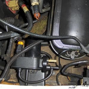
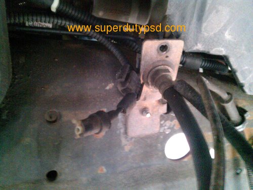
Dec 30, 2017 · diode_ee. I'm trying to figure out what the vacuum line shown disconnected in the photo goes to. The connected ends include the hub actuator for 4x4 and the vacuum pump. The disconnected line appeared to go under the battery box and was apparently broken on in end. From what I understand the vacuum pump runs the hubs and the climate controls.
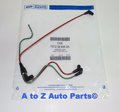
What's the official part name for the red and green vacuum (or is ...
2003-2007 Ford SuperDuty Diesel Truck Problems & How to Fix Them. If you're a diesel nut like me, you probably know that most people will steer clear of buying a 2003 to 2007 model year Ford Superduty Diesel truck. The 6.0L Powerstroke is known for having major problems. Most of these problems originate from the factory design.

Need vacuum diagram for '05 f350 6.0 diesel, squrrells got mine ...
Routing of vacuum line: A) From the pump to the canister is a single line B) Immediately after the canister is a tee to split into two lines ... 2005 F250 Super Duty Crew Cab 4x4-6.0 power Stroke diesel-Donahoe Racing 4.5 inch lift. Truxedo bed cover-35x12.5x17 BFG M/T tires. 9000 lb.winch in basket for front or rear receiver. Fab-Tec bumper ...

No vacuum pump in the gas versions - ford truck enthusiasts forums
Foreword This section of the Application and Installation Guide generally describes Diesel Fuels and Diesel Fuel Systems for Cat® engines listed on the cover of
Amazon.com: benefast 904-214 electric vacuum pump compatible with ...
An expert that has over 500 points. Champion: An expert who has answered 200 questions. Expert. 241 Answers. Re: Vacuum line diagram for 2003 f250 - Cars & Trucks. Any vacuum line , what you mean . Posted on Nov 18, 2011.
Ford bc3z9c493b - vacuum hose - 2011-2016 ford | oem ford part
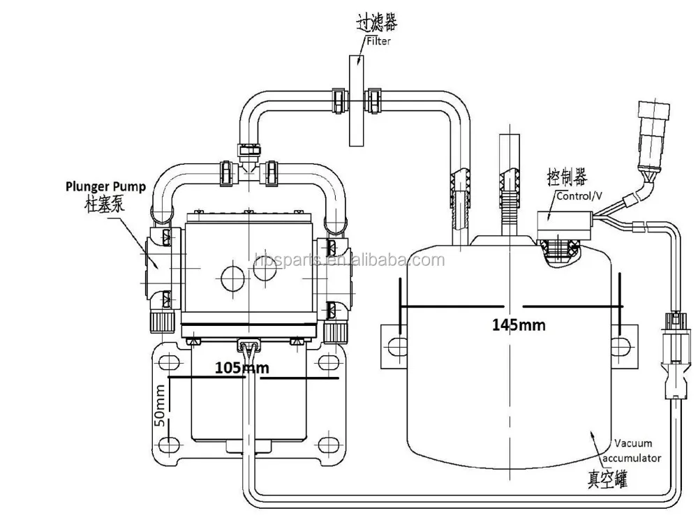
the vacuum pump has some hoses comeing off it --they go to a vacuum tank right next the the pump ---from the tank one hose goes to the a/c system and the other hose goes to a electric solenoid right by the tank---this is the 4x4 vacuum solenoid -take the vacuum hoses off this solenoid and one of them will have vacuum on it -I think its the red hose ---plug it up with something , make sure it ...
Need help with vacuum lines | ford powerstroke diesel forum
Ford F250-F350 1997 to 2004 Service Repair Manual. Ford F-250 / F-350 1997 - 2004 Service Workshop repair manual Download. 1998 Ford Cars Workshop Repair Service Manual. 1996-1999 Ford Vehicles Workshop Repair Service Manual (2.9GB DVD IMAGE!) FORD F-250 1997-2003 SERVICE MANUAL.
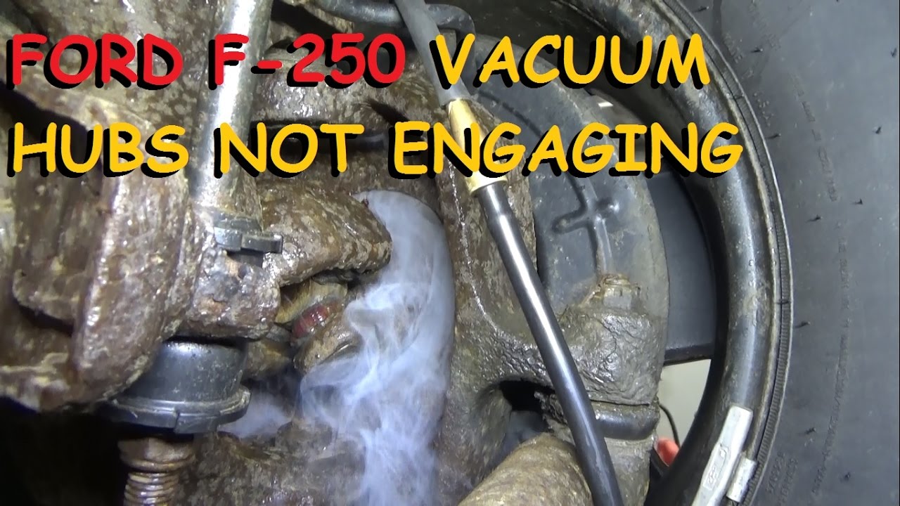
Ford f250 4x4 - vacuum hubs not engaging
E-450 Shuttle Bus - Passenger Side & Rear Wiring Diagram 94 F-550 Circuit Board Assembly Ver. 1 96 F-550 Circuit Board Assembly Ver. 2 98 E 450 & F-550 Circuit Board Assembly Ver. 3 100 F-550 Shuttle Bus -Wiring Diagram 107 Misc. Air & Electrical Diagrams and Schematics. 108 PARTS - SERVICE - WARRANTY 112

Ford 6.4l powerstroke high pressure fuel pump - know your parts
Diagrams and Schematics Index Section A - Front/Rear Axle Assemblies and Suspension Front Axle Rear Axle Driveshaft Suspension: Wheels Section B - Brake Assemblies and Components Hydraulic Brake System Master Cylinder Brake Booster Clutch/Brake Pedals Section C - Steering ...

New turbo idea.... - competition diesel.com - bringing the best ...

Understanding vacuum line diagram - ford truck enthusiasts forums ...

I just purcased a 2005 ford f250 4x4 6.0 diesel. when i turn on ...
Ac only blowing out defrost vents - ford truck enthusiasts forums
Ford super duty 4wd esof vacuum leak repair. - superdutypsd.com
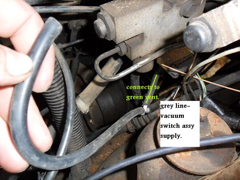
What is this grey hose? | the diesel stop

Ford ranger engine vacuum hose diagrams – the ranger station
Vacuum lines + 4x4 = what the heck?! help! :{ - diesel bombers

Ford ranger engine vacuum hose diagrams – the ranger station ...
Ford super duty diesel vacuum lines

Vacuum lines | ford powerstroke diesel forum

Turbo hose diagram questions & answers (with pictures) - fixya
Gray vacuum hose - ford truck enthusiasts forums
Vacuum leak/ vacuum pump runs constantly | ford powerstroke diesel ...
Where to plug vacuum lines???? | ford powerstroke diesel forum
Vacuum hose under left battery | ford power stroke nation
Small grey vaccum hose - ford truck enthusiasts forums
Pompa vakum rem listrik dengan tipe plunger,untuk diesel,elektrik ...
Defrost problem - ford truck enthusiasts forums

Gears magazine - engaging moments! ford's vacuum-actuated locking ...
Vacuum system on a '96 7.3l | the diesel stop
Vacuum lines diagram: i am looking for a diagram for vacuum lines ...

Solved: i need to find a vacuum line diagram for a f 250 - fixya

Worst case of vacuum line hell?| grassroots motorsports forum |
0 Response to "37 ford 6.0 diesel vacuum line diagram"
Post a Comment