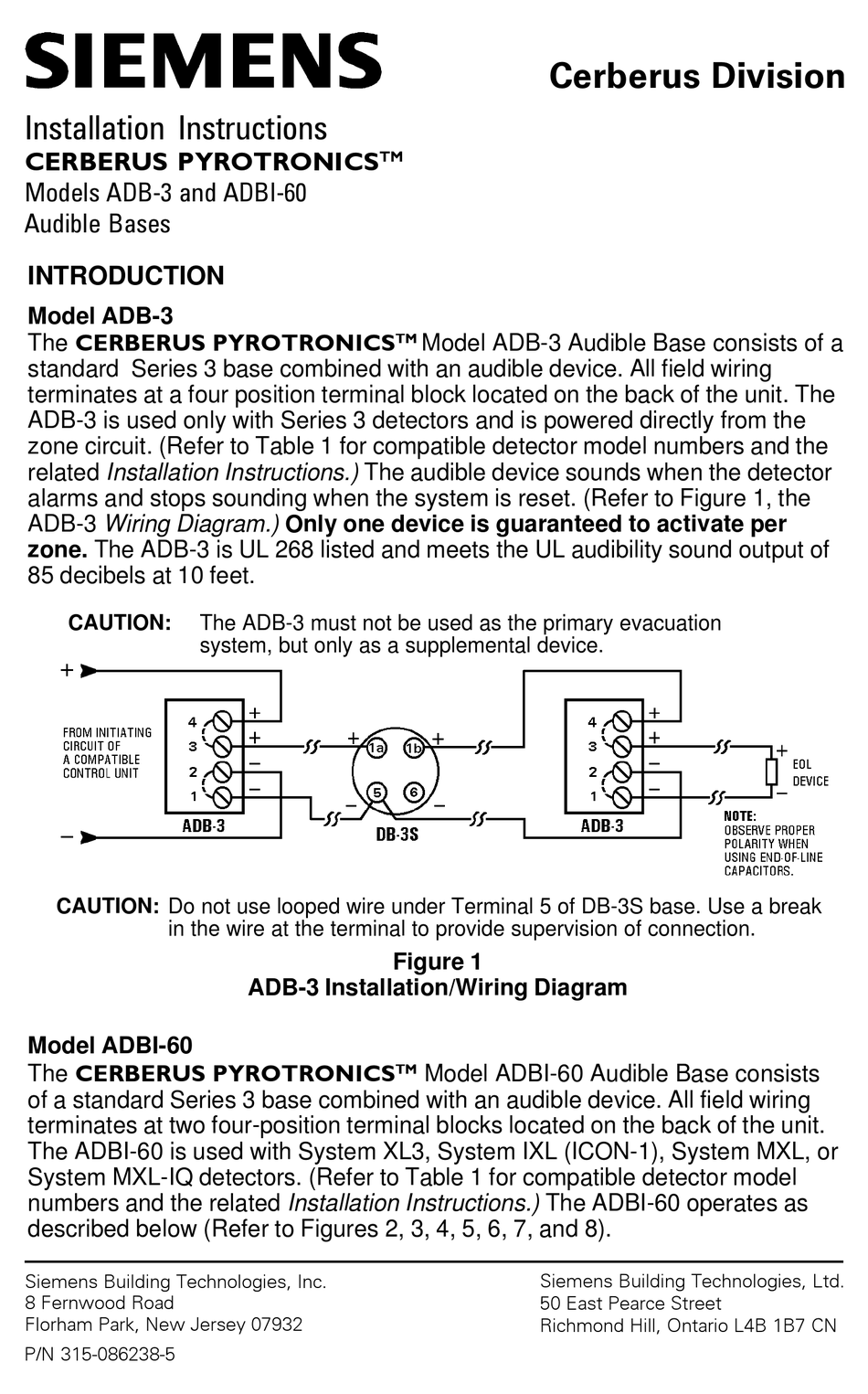
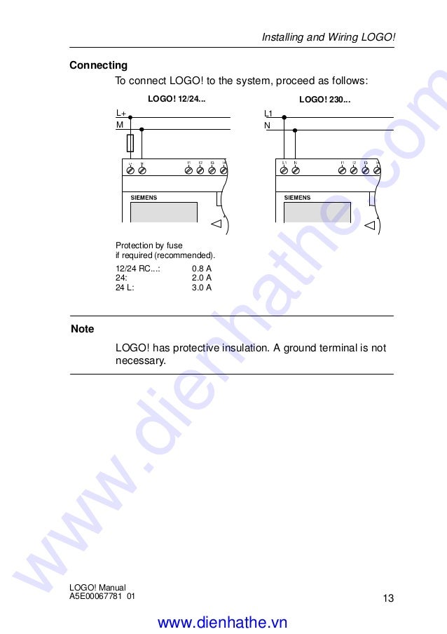
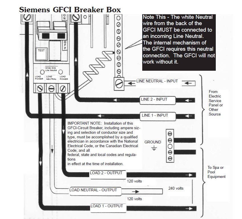
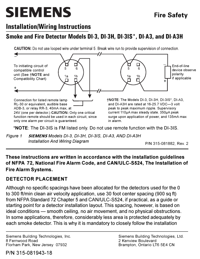
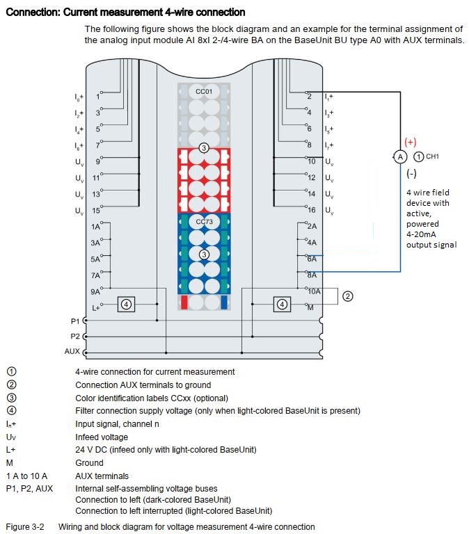
42 pyrotronics system 3 wiring diagram
DIMENSIONS AUDI SQ5. The manufacturer positions its model as a heated version for fans of dynamic driving. Its overall dimensions are: length 4671 mm, width 1983 mm, height 1635 mm, and wheelbase - 2824 mm. The Audi SQ5's ground clearance is 190 millimeters. The Cerberus Pyrotronics control panel model CP-35 is the basic control unit for the System 3 universal alarm control. It is of solid state circuitry and is ...4 pages
Basics 3 4.16 kV Bus 1-Line : Basics 4 600 V 1-Line : Basics 5 480 V MCC 1-Line : Basics 6 7.2 kV 3-Line Diagram : Basics 7 4.16 kV 3-Line Diagram : Basics 8 AOV Elementary & Block Diagram : Basics 9 4.16 kV Pump Schematic : Basics 10 480 V Pump Schematic : Basics 11 MOV Schematic (with Block included) Basics 12 12-/208 VAC Panel Diagram
Pyrotronics system 3 wiring diagram
Pyrotronics system 3 wiring diagram. Baltimore Fire Department Manual of Procedure, Pyrotronics, Inc installation of system's wiring. Manuals, installation installation instructions, catalogs, and more for Cerberus. The fire protection system Cerberus PRO from Siemens is the ideal choice for fast, reliable fire detection, alarm signaling, and ... 2.Separate all wiring for initiating devices (i.e., detectors, manual stations, etc.) from all other wiring in the System 3 enclosure. 3.INSULATE ALL CABLE DRAIN WIRES from any conduit or other earth grounded electrical box, including those in the System 3 enclosure. 4.Connect shield cable drain wire ONLY at the SPECIFIED location inside the Pyrotronics System 3 Wiring Diagram Source: wholefoodsonabudget.com Before reading a schematic, get common and understand all of the symbols. Read typically the schematic like a roadmap.
Pyrotronics system 3 wiring diagram. Description. The Fire Extinguishing System Control Module HC-35 is used to effect, either manually or automatically, the dis-.2 pages module connection diagrams. 3. Refer to the BI-35 Installation Instructions, P/N 315-086257, for detailed wiring information when using the AA-30U in ...4 pages Pyrotronics System 3 Wiring Diagram - Books - installation of system's wiring. SIEMENSIE E Model CP-35 WIRINGDIAGRAM. 1976. Baltimore Fire Department Manual of Procedure, Pyrotronics, Inc., DOWNLOAD. Pyrotronics Cp 30 Panel > Priority Downloads - The Cerberus Pyrotronics Dual Zone Module Model ZU-. 35, is designed to provide two independent initiating circuits. Up to thirty standard Cerberus Pyrotronics.4 pages
The DI-3, DI-A3, DI-B3, DI-3H, DI-A3H and DI-B3H detec-tors are fully compatible with other Cerberus Pyrotronics System 3 compatible detectors and may be intermixed on the same zone circuit. No more than thirty (30) detectors of any type of combination (other than thermals or manual stations) may be used on any one Cerberus Pyrotronics detector ... Q-Logic Technical Manual www.prideservice.com 7 I. OVERVIEW Q-LOGIC MODULES The basic system is a power module and a hand control. For adjusting seat position, an AAM module is added. For users who require specialized input devices, several options are available. This is a true plug-and-play system, and modules are View and Download Siemens System 3 manual online. Marine Fire Detection System.. System 3 control panel pdf manual download. wiring of two control panels is shown on pages 2 and 3 in the form of typical Wire Lists. Either a wiring list of this type or a complete point to point wiring diagram should be furnished with every system and should be kept as on-board documentation for future reference in system service and maintenance. NOTE: When designing Fire Control Systems
Pyrotronics System 3 Manual is a Windows image printing tool that makes it easy to print proof It s accessible after extraction with no need for installation. Manuals, installation installation instructions, catalogs, and more for Cerberus Pyrotronics fire alarm and security devices. Pyrotronics System 3 Wiring Diagram Source: wholefoodsonabudget.com Before reading a schematic, get common and understand all of the symbols. Read typically the schematic like a roadmap. 2.Separate all wiring for initiating devices (i.e., detectors, manual stations, etc.) from all other wiring in the System 3 enclosure. 3.INSULATE ALL CABLE DRAIN WIRES from any conduit or other earth grounded electrical box, including those in the System 3 enclosure. 4.Connect shield cable drain wire ONLY at the SPECIFIED location inside the Pyrotronics system 3 wiring diagram. Baltimore Fire Department Manual of Procedure, Pyrotronics, Inc installation of system's wiring. Manuals, installation installation instructions, catalogs, and more for Cerberus. The fire protection system Cerberus PRO from Siemens is the ideal choice for fast, reliable fire detection, alarm signaling, and ...
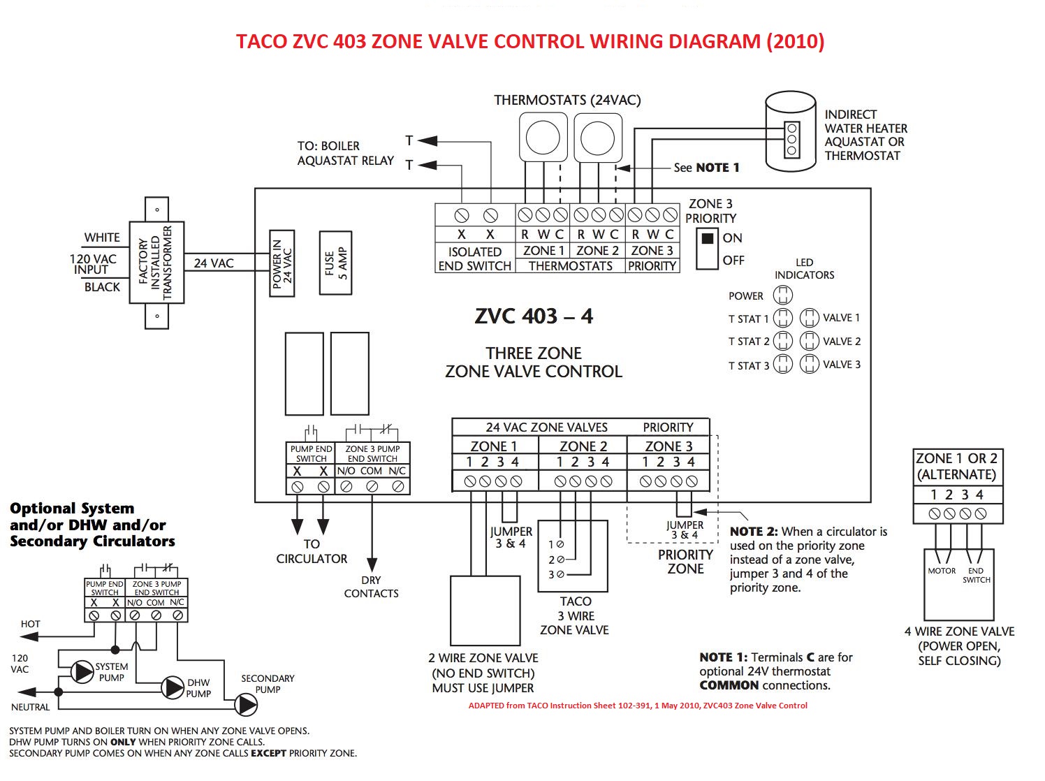
Zone Valve Wiring Manuals Installation Instructions Guide To Heating System Zone Valves Zone Valve Installation Inspection Repair Guide

Diagram 3 Phase Emergency Stop Wiring Diagram Full Electrical Circuit Diagram Home Electrical Wiring Electrical Wiring Diagram

Siemens Sinamics V20 Vfd Drive Remote Control 2 Wire And 3 Wire Control Parameter Set Up English Youtube
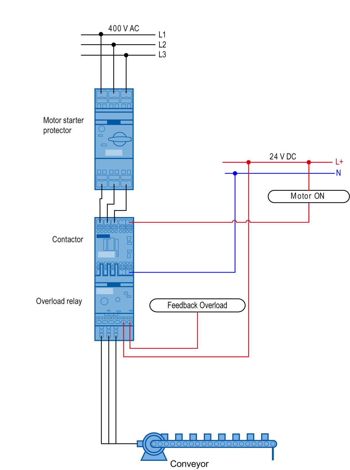
Sirius Innovations Load Feeder As A Direct Starter With Overload Relay Assembly An Id 41827698 Industry Support Siemens

Wiring And Block Diagrams Simatic Et 200sp Digital Input Module Di 8x24vdc Hs Id 109475339 Industry Support Siemens

Polygyr Three Position Converter Building Technologies Cm1n3486e 1 1999 Landis Staefa Division 1 2 3486 Polygyr Three Position Converter Sez61 3 0 10 V D C Control Electronic

Wiring And Block Diagram Simatic Et 200sp Digital Input Module Di 16x24vdc St Id 59753540 Industry Support Siemens
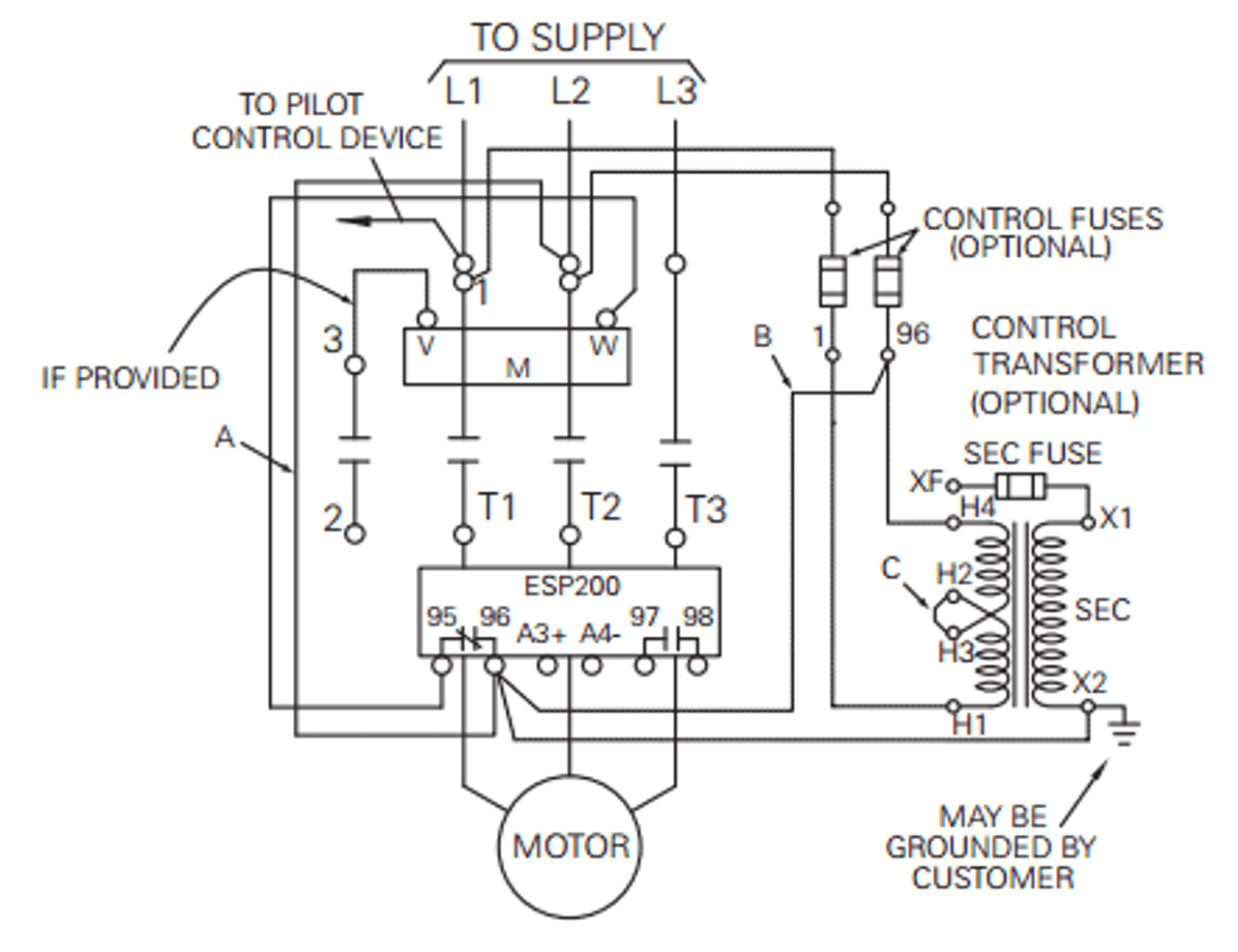









0 Response to "42 pyrotronics system 3 wiring diagram"
Post a Comment