41 shear diagram for triangular distributed load
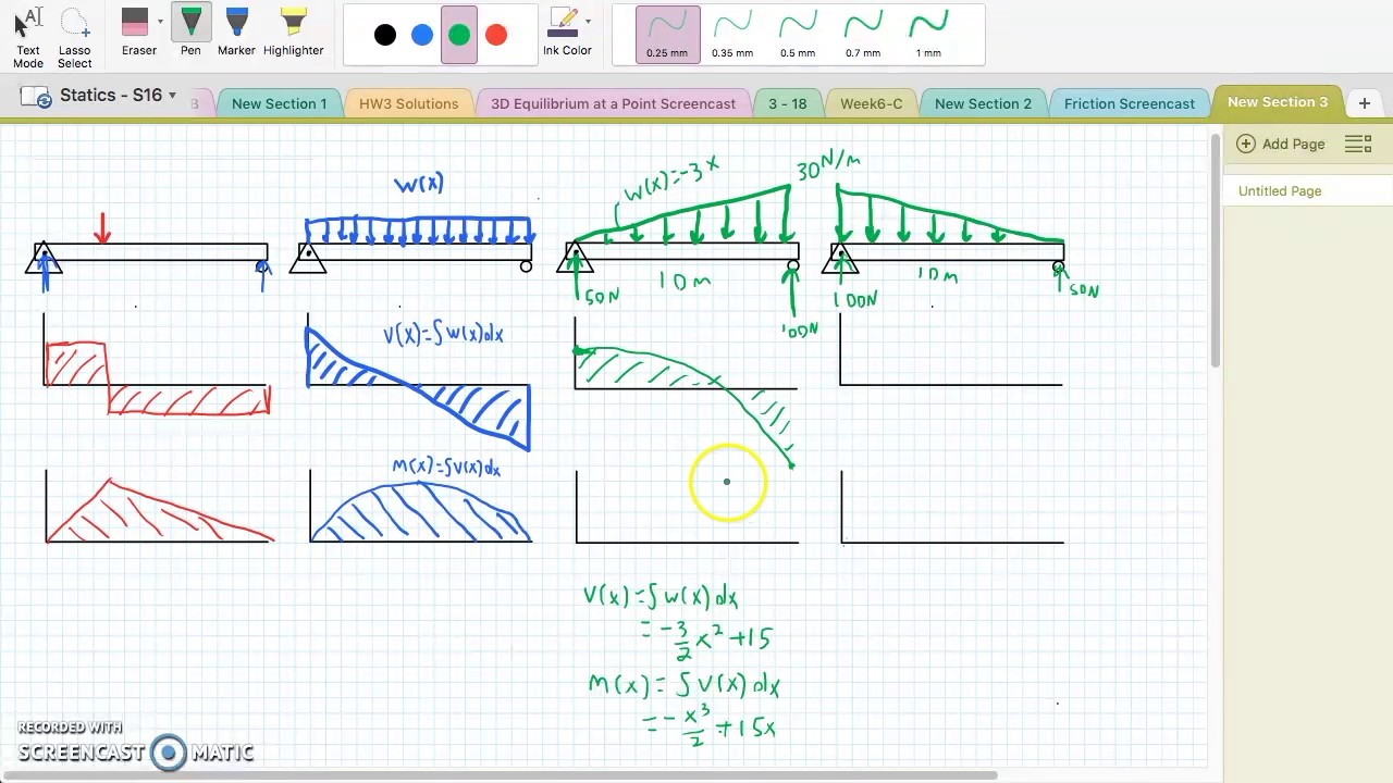
4 2 Mon Load Types For Beams And Frames Learn About Structures. The Beam Supports Triangular Distributed Load Shown Below With Wmax 500 Lb Ft Reactions At A And B Are Vertical Determine Resultant Shear Force On Cross Section Point. Solution To Problem 417 Shear And Moment Diagrams Strength Of Materials Review At Mathalino. In this video I go through an example problem of drawing shear and moment diagrams of a beam that has a triangular load on it.Check out some awesome Student ...
Triangular distributed load shear and moment diagram. You are trying to construct the moment diagram by jumping in the middle of the process without completing the basic steps 1 and 2 above first. These instructions will help you to calculate and draw shear and bending moment diagram as well as draw the resulting deflection.

Shear diagram for triangular distributed load
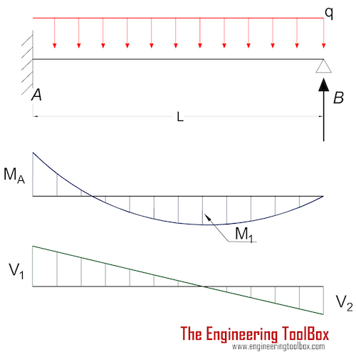
Beam Overhanging One Support - Uniformly Distributed Load Beam Overhanging One Support - Uniformly Distributed Load on Overhang Beam Overhanging One Support - Concentrated Load at End of Overhang Beam Overhanging One Support - Concentrated Load at Any Point Between Supports Beam Overhanging Both Supports - Unequal Overhangs ... 24:08Question (2) - Will the Shear Force Diagram for a Triangular Distributed Load be Parabolic? Why? 27K views ...8 Apr 2012 · Uploaded by CTSCIVIL BEAM DIAGRAMS AND FORMULAS Table 3-23 (continued) Shears, Moments and Deflections 13. BEAM FIXED AT ONE END, SUPPORTED AT OTHER-CONCENTRATED LOAD AT CENTER
Shear diagram for triangular distributed load. Ending at 0 is actually very important and is a good check that you did not make a mistake. From this completed diagram we can see that the maximum shear is 11.67 lb. Note: the shear line under a distributed load is linear for a constant distributed load and parabolic for a triangular distributed load. Solution To Problem 417 Shear And Moment Diagrams Mathalino. ... lo types of loading lied on beam 1 concentrated 2 uniformly scientific diagram a simple support beam supports the triangular distributed loading as shown in figure determine its maximum deflection when ei is constant study solved the cantilever beam is subjected to a triangular ... Shear and bending moment diagrams for a beam subjected to a triangular distributed load. Triangular Distributed LoadPoint LoadsDistributed LoadsExternal Coup... Problem 417 Beam carrying the triangular loading shown in Fig. P-417. [collapse collapsed title="Click here to read or hide the general instruction"]Write shear and moment equations for the beams in the following problems. In each problem, let x be the distance measured from left end of the beam. Also, draw shear and moment diagrams, specifying values at all change of loading
Step 2: Step 1: Knowing Forces Effect on Beams. - Knowing how different forces effect beams is important to be able to calculate the shear and bending moments. - A point force will cause a rectangular shear and a triangular bending moment. - A rectangular distributed load will cause a triangular shear and a quadratic bending moment. This is telling us that the linearly varying distributed load between E and F will produce a curved shear force diagram described by a polynomial equation. In other words, the shear force diagram starts curving at E with a linearly reducing slope as we move towards F, ultimately finishing at F with a slope of zero (horizontal). Distributed Loads ! For a triangle, this would be ½ the base times the maximum intensity. 15 Distrubuted Loads Monday, November 5, 2012 Distributed Loads ! The location of the equivalent point load will be 2/3 of the distance from the smallest value in the loading diagram. 16 Distrubuted Loads Monday, November 5, 2012 Its because the shear diagram is triangular under a uniformly distributed load. Chapter 4 shear and moment in beams. In each problem let x be the distance measured from left end of the beam. 7 ft 10 ft a r. Also draw shear and moment diagrams specifying values at all change of loading positions and at points of zero shear.
WITH SHEAR AND MOMENT DIAGRAMS American Forest & Paper Association w R V V 2 2 Shear M max Moment x DESIGN AID No. 6. ... Figure 18 Beam Overhanging One Support-Uniformly Distributed Load x 1 Shear M 2 M 1 R 1 (1- a 2) Moment V 3 V 2 (1- a 2) 2 2 2 x a w( + a) R 2 V 1 7-44 B. AMERICAN FOREST & PAPER ASSOCIATION V 2 M max x x 1 a Moment ... Distributed loading is one of the most complex loading when constructing shear and moment diagrams. This causes higher order polynomial equations for the shear and moment equations. Recall, distributed loads can be converted to equivalent forces which are easier to work with. Also, complex, non-uniform distributed loads can be split into simpler distributed loads and treated separately. Find distributed load on beam ex. Use this beam span calculator to determine the reactions at the supports draw the shear and moment diagram for the beam and calculate the deflection of a steel or wood beam. Triangular distributed load shear and moment diagram. We had a tutorial similar before but this one uses no differential equations enjoy. Distributed loads cause the shear diagram to decrease or increase in a way that can be modeled by a function. You can model the distributed load as a function and then integrate that function to get the shear function (see the Quick Tips at the top for more specifics on this).
Shear And Moment Diagrams S B A Invent Nursing Student Tips Civil Engineering Design In This Moment
Problem 416 Beam carrying uniformly varying load shown in Fig. P-416. [collapse collapsed title="Click here to read or hide the general instruction"]Write shear and moment equations for the beams in the following problems. In each problem, let x be the distance measured from left end of the beam. Also, draw shear and moment diagrams, specifying values at all change of loading

Solved The Cantilever Beam Ab Shown In The Figure Is Subjected To A 1 Answer Transtutors
Its because the shear diagram is triangular under a uniformly distributed load. Please consider supporting the channel. X r a 40 lb v m pass a section through the beam at a point between the right end of the distributed load and the right end of the beam. Distributed shear the value of the moment diagram will have changed by the magnitude of ...
Solution To Problem 417 Shear And Moment Diagrams Strength Of Materials Review At Mathalino
Its because the shear diagram is triangular under a uniformly distributed load. Triangular distributed load shear and moment diagram. Fig6 formulas for finding moments and reactions at different sections of a simply supported beam having udl at right support. Beam formulas with shear and moment diagrams.
2
directly from the load diagram, and then construct the bending moment diagram from the shear force diagram. This technique, called the area method, allows us to draw the shear force and bending moment diagrams without having to derive the equations for V and M. First consider beam subjected to distributed loading and then

The Cantilever Beam In Fig 7 13a Is Subjected To A Triangular Line Load Determine The Stress Resultants Through Integration Holooly Com
Since a distributed load varies the shear load according to its magnitude it can be derived that the slope of the shear diagram is equal to the magnitude of the distributed load. Jan 28, · Step 2: Construct the shear force diagram for the beam with these reactions. Step 3: Using the shear force diagram, construct the bending moment diagram.
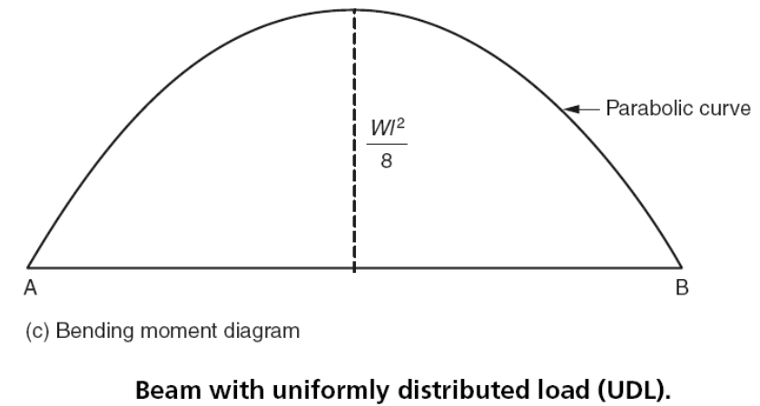
Beam Analysis Beam With Uniformly Distributed Load Udl Engineersfield
I'm trying to calculate the shear force diagram in terms of x, but I'm unsure about the intensity w(x) of the triangular load distribution between 0m≤x<3m. I ...1 answer · Top answer: Your procedure is correct, but you have made a mistake with the sign convention. Apparently you are using the same convention as I do, where a ...

The Shear Force Diagram Of A Cantilever Beam Of Length L And Carrying A Uniformly Distributed Load Of W Per Unit Length Will Be
7:19This video shows how to solve beam with triangular load. In this video triangular load has been calculated ...13 Jul 2019 · Uploaded by Civil Engineering

Pin On Figaw
Triangular distributed load shear and moment diagram. These instructions will help you to calculate and draw shear and bending moment diagram as well as draw the resulting deflection. Lesson 60 shear moment diagram the equation method. Setting the bending diagrams of beam. Invert diagram of moment bmd moment is positive when tension at the ...

Shear Force And Bending Moment Diagrams For A Simply Supported Beam With Uniform Varying Load Mechanical Engineering Concepts And Principles
Triangular distributed load shear and moment diagram. You are trying to construct the moment diagram by jumping in the middle of the process without completing the basic steps 1 and 2 above first. Knowing the distribution of the shear force and the bending moment in a beam is essential for the computation of stresses. 7 ft 10 ft a r.

The Frame Supports The Triangular Distributed Load Shown Determine The Normal And Shear Stresses At Point D That Act Perpendicular And Parallel Respectively To The Grains The Grains At This Poi
•For a triangular distributed load, the location of the resultant force is 1/3 of the length of the load, from the larger end 5 kN/m 4 m 4 m x m x x b m m 3 4 * 4 3 1 0 3 1 0 1.33 m 10 kN . Integral Method •The magnitude of the resultant force is given by the integral of the curve defining the force, w(x) 5 m 2 m
4 4 Relation Among Distributed Load Shearing Force And Bending Moment Engineering Libretexts
In this video I go through an example problem of drawing shear and moment diagrams of a beam that has a triangular load on it.Check out some awesome Student ...

Bending Moment And Shear Force Diagram Of A Cantilever Beam
14:35Example of drawing a shear and moment diagram graphically for a simply supported beam with a ...10 May 2012 · Uploaded by structurefree

Shear Force Bending Moment With Triangular Load On Beam Youtube
BEAM FORMULAS WITH SHEAR AND MOMENT DIAGRAMS Uniformly Distributed Load Uniform Load Partially Distributed Uniform Load Partially Distributed at One End Uniform Load Partially Distributed at Each End Load Increasing Uniformly to One End Load Increasing Uniformly to Center Concentrated Load at Center Concentrated Load at Any Point Two Equal Concentrated Loads Symmetrically Placed Two…

Load Shear Moment With Distributed Load Mp4 Youtube
13:39This video shows the shear force and bending moment diagram of a cantilever beam with triangular load. A ...3 Jun 2020 · Uploaded by Civil Engineering

Moment At Height X Of The Structure For Triangular Distributed Lateral Download Scientific Diagram
13:30Be sure to watch my previous video for finding the shear and moment diagram for a simply supported beam ...23 Nov 2016 · Uploaded by Dr Soltys Screencasts

A Simply Supported Beam Under Triangular Load Download Scientific Diagram
Chapter 4 shear and moment in beams. The distributed loads can be arranged so that they are uniformly distributed loads udl triangular distributed loads or trapezoidal distributed loads. You are trying to construct the moment diagram by jumping in the middle of the process without completing the basic steps 1 and 2 above first.

Cantilever Beam Deflection Calculator
A Propped Cantilever Beam Is Loaded By Triangular Distributed Load From To C Sec Figure The Has Peak Intensity Q 0 10 Lb Ft Length Of. A Simple Support Beam Supports The Triangular Distributed Loading As Shown In Figure Determine Its Maximum Deflection When Ei Is Constant Study. 000341 Calculation Of Bending Moment Shear Force Amount Deflection ...

Ch 7 Internal Forces With Triangular And Rectangular Distributed Loads Part 2 Youtube
Add a Distributed Load. Start Location (m): ... Triangular/trapezoidal Load. Setting the bending diagrams of beam. Calculate the reactions at the supports of a beam. Bending moment diagram (BMD) Shear force diagram (SFD) Axial force diagram. Invert Diagram of Moment (BMD) - Moment is positive, when tension at the bottom of the beam ...

A Beam Is Subjected To A Triangular Distributed Load Whose Value At Right End Of The Homeworklib
BEAM DIAGRAMS AND FORMULAS Table 3-23 (continued) Shears, Moments and Deflections 13. BEAM FIXED AT ONE END, SUPPORTED AT OTHER-CONCENTRATED LOAD AT CENTER
Triangular Distributed Load Shear And Moment Diagram Wiring Site Resource
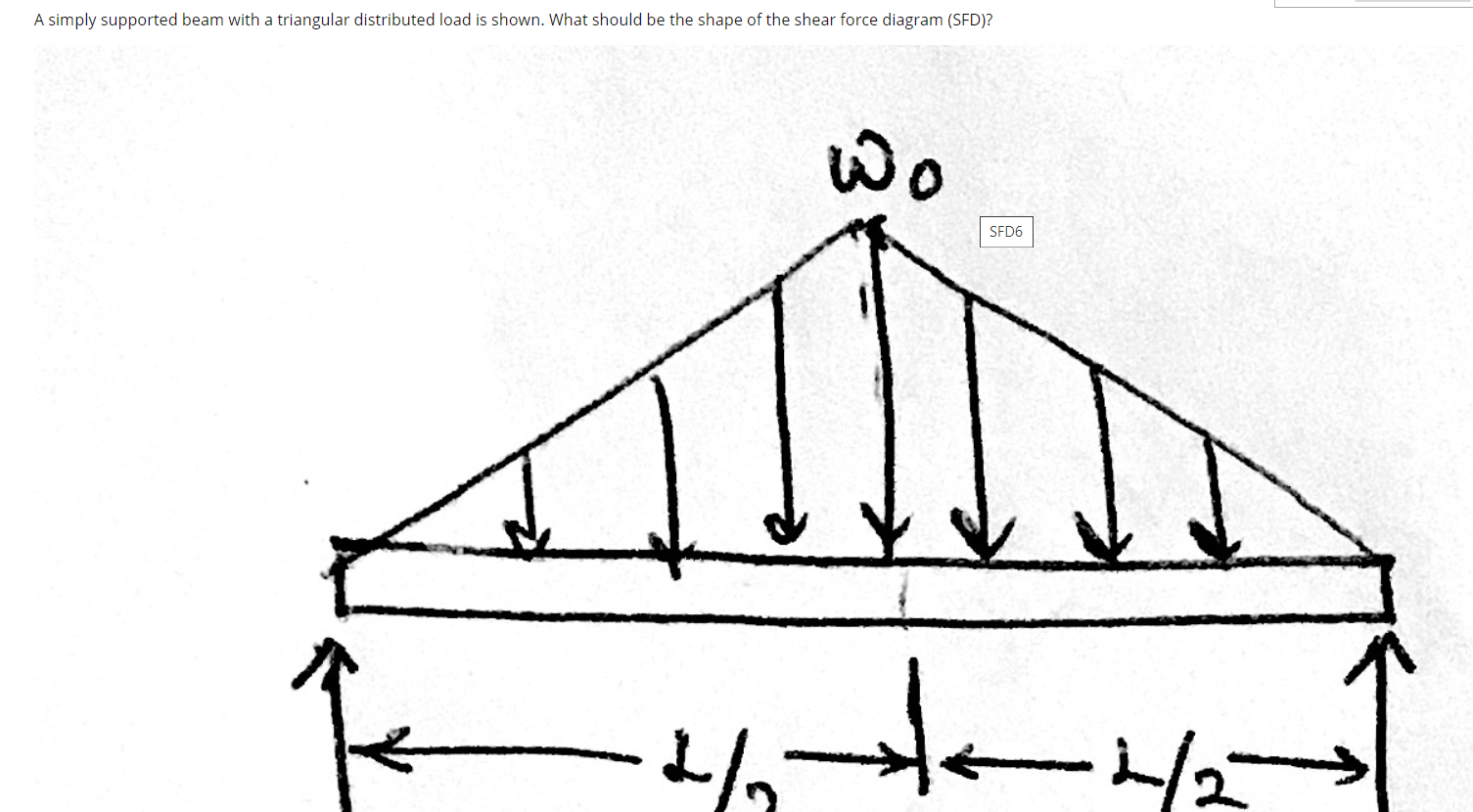
24:08Question (2) - Will the Shear Force Diagram for a Triangular Distributed Load be Parabolic? Why? 27K views ...8 Apr 2012 · Uploaded by CTSCIVIL

The Simply Supported Beam Shown In The Figure Below Supports The Triangular Distributed Loading A Determine The Reaction At A B Draw The Bending Moment Diagram And C Determine Its Maximum Deflec
Beam Overhanging One Support - Uniformly Distributed Load Beam Overhanging One Support - Uniformly Distributed Load on Overhang Beam Overhanging One Support - Concentrated Load at End of Overhang Beam Overhanging One Support - Concentrated Load at Any Point Between Supports Beam Overhanging Both Supports - Unequal Overhangs ...
Solved Shows A Three Hinged Parabolic Subjected To Point Loads Of 15 Kn And 25 Kn At Points D And E Respectively With Triangular Distributed Load O Course Hero
Triangular Load Mathalino Reviewers Tagged With Triangular Load

The Cantilever Beam In Fig A Carries A Triangular Load The Intensity Of Which Varies From Zero At The Left End To 360 N M At The Right End In Addition A 1000 N

Cantilever Beam Shear Force And Bending Moment Diagram With Triangular Load Youtube
What Is The Distance At Which The Triangular Udl Is Acting On In This Problem Engineering Stack Exchange

Plain And Civil Example 4 3 14 Beam Support Reactions For Triangular Loads
Solved A Simply Supported Beam With A Triangular Distributed Chegg Com
Beams Fixed At Both Ends Continuous And Point Loads
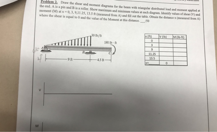
Solved Problem 2 Draw The Shear And Moment Diagrams For The Chegg Com

Sfd Bmd Example 3 Simply Supported Beam With Triangular Loading Youtube

Shear And Moment Diagram Example 2 Mechanics Of Materials And Statics Youtube

Part A Draw The Moment Diagram For The Beam Follow The Sign Convention Part B Draw The Shear Diagram For The Beam Follow The Sign Convention Study Com
Shear And Moment Diagrams For Combined Loadings Youtube
Beams Fixed At One End And Supported At The Other Continuous And Point Loads
A Simply Supported Beam 6m Long Is Subjected To A Triangular Load Of 6000n As Shown In Fig Below Sarthaks Econnect Largest Online Education Community

Sfd Bmd Shear Force Bending Moment Diagram

A Cantilever Under Linear Distributed Load The Shear Force And Bending Download Scientific Diagram
Question 10 Deriving V And M Equations For A Simply Supported Beam With A Triangular Loading Youtube

A Simple Support Beam Supports The Triangular Distributed Loading As Shown In The Figure A Determine Its Maximum Deflection When Ei Is Constant Study Com

Triangular Load Shear And Moment Diagram Example Problem Calculus Explained Youtube
0 Response to "41 shear diagram for triangular distributed load"
Post a Comment