40 ignition coil ballast resistor wiring diagram
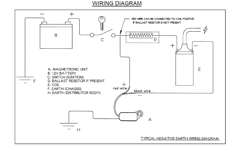
The typical automotive ignition system prior to 1974 consisted of a coil and ballast resistor, with breaker points to interrupt the current flow when a spark was needed. The job of the ballast resistor was to inhibit current to a level that would not overheat the coil. This simple system is easy for even the novice mechanic to wire. If there is power there, the ballast resistor is likely bad. Reconnect the wires and measure the voltage at the positive side of the coil. If you see 8-13 volts ...
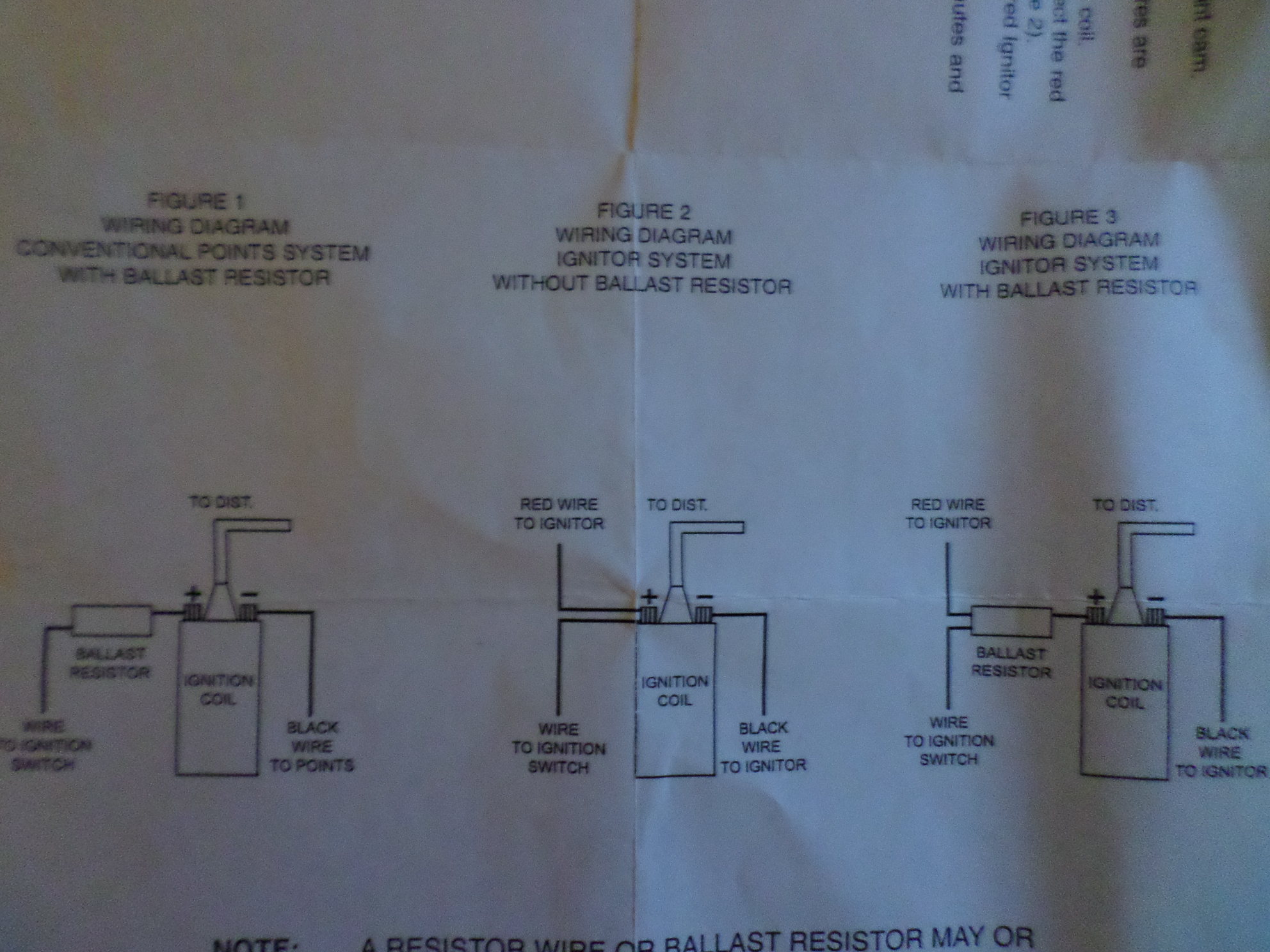
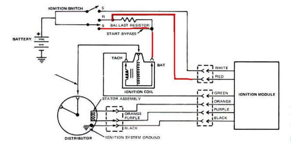
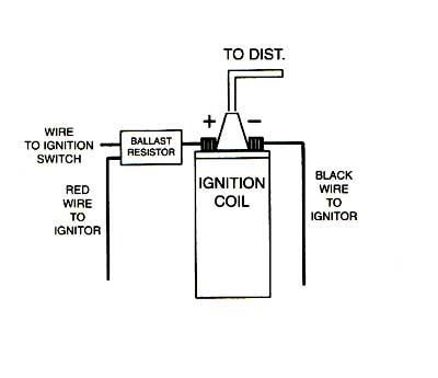
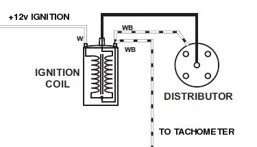
COIL WIRE. TO IGNITION SWITCH. RED WIRE. BLACK WIRE. RESISTANCE WIRE. BALLAST RESISTOR. The Ignitor can also be installed in applications retaining the ...4 pages
Ignition coil ballast resistor wiring diagram
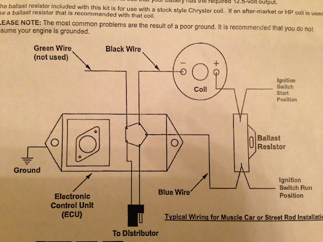
Ignition Coil Ballast Resistor Wiring Diagram. Print the cabling diagram off plus use highlighters to be able to trace the circuit. When you use your finger or even follow the circuit together with your eyes, it is easy to mistrace the circuit. 1 trick that We use is to print the same wiring picture off twice. Step 4: Install Ballast Resistor. Set the ballast resistor up to the firewall and screw the clamps in place. Step 5: Connect Wires to Positive. Strip the end of the positive wire from the ignition, and connect it to the positive end of the resistor. From the other terminal on the resistor a wire goes to the positive on the coil. 2020-12-15 · Ignition Coil Ballast Resistor Wiring Diagram. Print the cabling diagram off plus use highlighters to be able to trace the circuit.
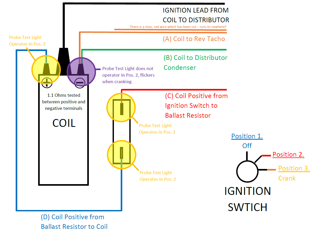
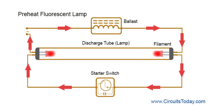
Ignition coil ballast resistor wiring diagram. Ignition Coil Ballast Resistor Wiring Diagram. Find this Pin and more on Wiring Diagram Free by Wiring Forums. Led Fluorescent. Led Tubes. Rx7. Fancy Cars. Ignition Coil. Diagram. Wire. Testing for a ballast resistor. resister or resister wire before and in series with the ignition coil. This is vital in choosing the correct ignition coil for the vehicle. 1. Test procedure: 1.1 Switch off ignition. 1.2 Disconnect all wires from coil (-). probe to coil (+) and black probe to chassis/earth. Note the voltage, which. Description : Ignition Coil Ballast Resistor Wiring Diagram with Ignition Coil Ballast Resistor Wiring Diagram, image size 609 X 360 px, and to view image details please click the image. Here is a picture gallery about ignition coil ballast resistor wiring diagram complete with the description of the image, please find the image you need. About Press Copyright Contact us Creators Advertise Developers Terms Privacy Policy & Safety How YouTube works Test new features Press Copyright Contact us Creators ...
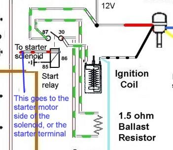
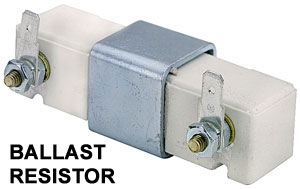
A resistor wire or ballast resistor may or may not be included in the original equipment. The typical automotive ignition system prior to 1974 consisted of a coil and ballast resistor with breaker points to interrupt the current flow when a spark was needed. Diagram Wiring Diagram Ballast Resistor Ignition Coil Full Version Hd Quality … A ballast resistor is a resistor inserted into a circuit to compensate for different changes. The coil does not go direct to earth. Mopar Ballast Resistor Wiring Diagram Basic Electronics Wiring Diagram I am planning to replace the distributor with a mallory unilite pointless distributor the instructions emphasize the necessity of either a ballast resistor […] Our Ballast Resistor is designed to be used in conjunction with our available External Resisted Ignitions Coils. External Resisted Ignition Coils have an internal resistance of 1.5 Ohms and when combined with the Ballast Resistor you get a total resistance of 3.0 Ohms which is necessary for 12 Volt ignitions systems. 2020-12-15 · Ignition Coil Ballast Resistor Wiring Diagram. Print the cabling diagram off plus use highlighters to be able to trace the circuit.
Step 4: Install Ballast Resistor. Set the ballast resistor up to the firewall and screw the clamps in place. Step 5: Connect Wires to Positive. Strip the end of the positive wire from the ignition, and connect it to the positive end of the resistor. From the other terminal on the resistor a wire goes to the positive on the coil. Ignition Coil Ballast Resistor Wiring Diagram. Print the cabling diagram off plus use highlighters to be able to trace the circuit. When you use your finger or even follow the circuit together with your eyes, it is easy to mistrace the circuit. 1 trick that We use is to print the same wiring picture off twice.
Mk2 Escort Cranking And Firing But Dies Straight Away Tech Talk Oldschool Co Nz
Pertronix Ignition And Ballast Resistor Moparts Forums

Ignition Coil Distributor Wiring Diagram Wiring Forums In 2021 Ignition Coil Coil Electrical Wiring Diagram
Electronic Ignition Diagram

Pin By Jim Matney On How To In 2021 Ignition Coil Ignite Ignition System
Ignition Troubleshooting
Ignition Issue 71 302 Only Runs In Crank Position Ford Mustang Forum
Electronic Ignition And Ballast Resistors Question Mg Engine Swaps Forum Mg Experience Forums The Mg Experience
Will Bypassing Ballast Resistor Damage Stock Ignition Module In Engine Transmission Rear End Page 1 Of 2
Ballast Resistor Working Uses Applications And Types

Norton Commando Wiring Diagram Tri Spark
1

Ballast Resistor Removed The E Type Forum
Wiring Diagram For 1600 With Ballast Resistor Mga Forum Mg Experience Forums The Mg Experience
Technical Please Help Ballast Resistor Wiring Ignition Wiring The H A M B

What A Ballast Resistor Do

Bypassing Ballast Resistor For A Bodies Only Mopar Forum
Tr7 Connection To Distributor Coil Ballast Tr7triumph Com
12v Coil Or Resistor Vintage Mustang Forums

Ignition Coil Ballast Resistor Wiring Diagram Helloo Ignition Coil Coil Ballast
Igniter And Ballast Wiring With Painless Ih8mud Forum

Anything I Can Substitute For A Ballast Resistor Ford Truck Enthusiasts Forums
Ballast Resistor Chevy Tri Five Forum

Big Block Wiring

Ballast Resistor

Electronic Ignition Conversion Help For A Bodies Only Mopar Forum

Rubber Bumper Mgb Check You Have The Correct Coil Mgb Tips Mods And Maintenance
Mopar Electronic Ignition Wiring Schematic Question For A Bodies Only Mopar Forum
Technical Differences In Ballast Resistors Help Me Get My Wheels Running Please The H A M B
1956 F100 Ignition Coil Low Voltage Ford Truck Enthusiasts Forums
Cuore Resistance Cuore Pakwheels Forums
Ballast Resistor Working Uses Applications And Types
How To Test An Ignition Coil

Installation E Spark

Does This Duraspark Wiring Need The Ballast Resistor

Cara Kerja Ballast Resistor Pada Saat Di Starter Rankaian Bisa Otomotif
1

Model T Ford Forum Texas T Dist Keeps Burning Condensers Why
Choosing A Coil
Troubleshooting Lucas Points
0 Response to "40 ignition coil ballast resistor wiring diagram"
Post a Comment