40 copeland potential relay wiring diagram
A/C Copeland Scroll® .. Compressor wiring diagrams with motor winding connec- Data-Copeland Scroll Compressors, and Electrical. Refer to original equipment wiring diagrams. Care must be taken to ensure that wiring or . The Copeland Scroll compressor's inherent. Copeland Scroll compressors have a voltage tolerance of + 10%. Copeland Potential Relay Wiring Diagram Run Capicator For A run relay helps to prevent wires from overloading and overheating. Overheated wires can spark a fire. They pull off not prevent volt spikes. If a relay switch stops vigorous for some reason, it is practical to exam it. This is unquestionably applicable in automobiles, as one switch can ...
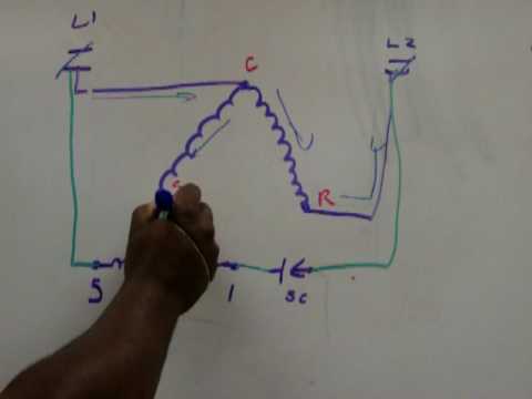
This is the wiring of the potential relay. This video is part of the heating and cooling series of training videos made to accompany my websites: www.grayco...

Copeland potential relay wiring diagram
The methods to check.CSR motor diagram. Relay - Potential Compressor - Unit Ground Line 1 Line 2 Ground Start Winding Main Winding Control External or Internal Thermal Protector. ... We Provide 20 for you about copeland csr compressor wiring diagram- page 1.Single phase compressor for air-condition - Electrical Engineering Centrewindow ac ... If you are looking for copeland potential relay 040 0166 19 wiring you have come to the perfect site. Instructions for wiring a standard automotive relay with descriptions of the pin out and the schematic. This is the wiring of the potential relay. Ribu1c wiring diagram lovely generous potential relay wiring diagram. Copeland Potential Relay 040 0166 19 Wiring | Wiring Diagram - Potential Relay Wiring Diagram. You are able to often depend on Wiring Diagram as an important reference that may assist you to preserve money and time. With the assist of this e-book, you'll be able to very easily do your own personal wiring tasks.
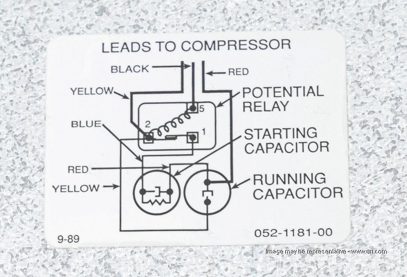
Copeland potential relay wiring diagram. • 2 relays replace over 25 O.E.M. relays • Universal break-off bracket on each relay. Simply snap off parts not needed • UL and CSA listings available One-On-One™ Direct Replacement Potential Relays The relays are exact replacements for Bristol & Copeland applications. They conform to specifications and in most cases are the one-on-one™ Potential relay /940-0140-03 I did some research and found these xref numbers: Start Capacitor Wholesaler P/N 914-0053-14 Copeland P/N 014-0053-30 Potential Relay Wholesaler P/N 940-0140-03 Copeland P/N 040-0166-02 GE P/N 3ARR3T25S5 The unit already had a potential relay installed. Copeland Compressor Wiring Diagram. accordance with the position of the capacitors and relay shown on the wiring diagram. Compressor model. Run capacitor. Start capacitor. Potential relay. MISWIRING IS MURDER. It is very easy to miswire a compressor, but the results can be deadly. The purpose of this booklet is to dem- onstrate how to wire a. 55 New Potential Relay Wiring Diagram- A govern relay is used in the automotive industry to restrict and regulate the flow of electricity to various electrical parts inside the automobile. They permit a small circuit to direct a later flow circuit using an electromagnet to rule the flow of electricity inside the circuit. ... Copeland Condenser ...
Copeland Potential Relay 040 0166 19 Wiring | Wiring Diagram - Potential Relay Wiring Diagram. You are able to often depend on Wiring Diagram as an important reference that may assist you to preserve money and time. With the assist of this e-book, you'll be able to very easily do your own personal wiring tasks. A - Hermetic Compressors Emerson Climate Technologies 2014DS-78 R2 (2/16)4 AF - Compressor Parts Model Start Capacitor Run Capacitor Current Relay Potential Relay Overload Copeland start/run/potential relay question. Swapped compressor today in a Carrier 3-ton rooftop, with the comp. supplier gave me a 35Uf cap, a 178Uf "start cap" & a potential relay, original compressor just had L1 to Common, L2 to Run & 40Uf cap to Start terminals, no diagrams & no Copland website literature, supplier sent me only thing ... Diagram Page. Copeland semi hermetic compressors wiring diagram for compressor technical information open thermal overload on emerson cr22k6me pf1 111dm electrical handbook symptom cause troubleshooting achr news basic controls of air 4 china scroll single phase got a northern leader waterfurnace motors page solid state starting relays from to z hvac talk heating refrigeration lennox hs29 311 ...
Potential Relay Wiring Diagram - compressor potential relay wiring diagram, copeland potential relay wiring diagram, mars potential relay wiring diagram, Every electrical arrangement consists of various distinct components. Each part should be set and connected with different parts in particular way. If not, the structure won't function as it ... Copeland Potential Relay Wiring Diagram Run Capicator For Hvac Air Conditioning Electrical Diagram Air Conditioner Compressor . Wd ma1a wd ma1a ma1a mh1a. Copeland 3 phase compressor wiring diagram. Emerson Copeland Compressor Electronics For Stream Compressors Installation Guide Manuals. Technical information assembly instructions scroll ... Compressor Potential Relay Wiring Diagram - wiring diagram is a simplified welcome pictorial representation of an electrical circuit.It shows the components of the circuit as simplified shapes, and the capacity and signal contacts amid the devices. 12+ Copeland Compressor Wiring Diagram Single Phase. Single phase cr6/5t bristol tecumseh carlyle danfoss zrk5/k3/kc legend voltage code h20b153abc. Fancy single phase pressor wiring diagram with relay elaboration from wiring diagram for copeland compressor , source:itseo.info repair parts for the campbell hausfeld model wl thanks for visiting our website, contentabove…
Copeland Potential Relay 040 0001 02 040 0001 11 North America Hvac
Copeland Potential Relay Wiring Diagram Run Capicator For Hvac Air Conditioning Electrical Diagram Air Conditioner Compressor . The digital compressor controller is designed only for single phase copeland scroll digital compressors and three phase copeland scroll digital and discus digital compressors.
Embraco Com
Compressor Potential Relay Wiring Diagram - One of the most hard automotive repair tasks that a mechanic or fix shop can give a positive response is the wiring, or rewiring of a car's electrical system.The hardship in reality is that all car is different. subsequent to a pain to remove, replace or repair the wiring in an automobile, having an accurate and detailed compressor potential ...

The Misunderstood Lockout Relay Hvac School
Copeland Potential Relay Wiring Diagram. Copeland potential relay wiring diagram hermetic compressor voltage relays capacitor chart tifom what happened to elect handbook start a cscr motor electrical single phase wire diagrams 45 beautiful danfoss. Diagram Copeland Potential Relay Wiring Run Capicator For Full Version Hd Quality Diagramia ...

Hvac Motor Start Relays Hvac Troubleshooting
In the rubber plug that plugs into the compressor, there is a rectifier that changes the voltage DC. Do NOT put 24vlts AC to the solenoid. This will burn up the coil. (COPELAND K1 SCROLL COMPRESSOR ONLY) 1 Fig. 6—MH1A- (A) Heat Pump Schematic Diagram and Electric Heater Wiring Options v, 1 Phase, 60 Hertz A 5KW 5KW 5KW TOP 2 BANKS NOTES ...
Potential Relay Youtube
Wholesaler Copeland® GE P/N Pick-up Drop Out Cont. Volt Freq. P/N Brand P/N Volts Volts Rating Potential Relay Data 940-0001-82 040-0166-39 3ARR3T3U5 220 - 240 40 - 90 332 60
Digitalassets Reecegroup Com Au
Potential Relays. Know your potential starting relays solid state p m relay model pm a3c2 wiring diagram 14 voltage symptom cause troubleshooting achr news hard start hvac school electrical handbook basic controls of air jd1914 what happened to e2 motorotor ppt copeland semi hermetic compressors final2 online version a4 cdu catalogue 20pp scroll two stage problems e 2 compressor magnetic 2003 ...

Emerson Ae4 1302 R10 K4 Refrigeration Copeland Scroll Compressors 7 5 15 Horsepower User Guide Manuals
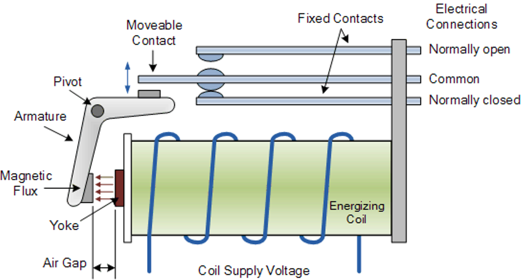
55 New Potential Relay Wiring Diagram- A govern relay is used in the automotive industry to restrict and regulate the flow of electricity to various electrical parts inside the automobile. They permit a small circuit to direct a later flow circuit using an electromagnet to rule the flow of electricity inside the circuit.
1
Electrical wiring diagram tfd 3 phase. Universal bracket allows using the existing mounting of the potential relay being replaced. Copeland outdoor condensing unit. The purpose of this booklet is to dem onstrate how to wire a. Replaces both 3 and 5 terminal potential relays supr has dimensions identical to the industry standard potential relay.

Current Relay Cut Away Online Hvac Training Youtube
Copeland Potential Relay Wiring Diagram Run Capicator For Hard Start Wiring Diagram Wiring Diagrams All Danfoss Current Relay Wiring DIAGRAM] 240v Airpressor Wiring Diagram FULL Version HD An automobile run relay adjust in size from the 3-pin to 5-pin types. The 4-pin type is generally used throughout the automobile.
Rses Org
Potential Relay Wiring Diagram - compressor potential relay wiring diagram, copeland potential relay wiring diagram, mars potential relay wiring diagram, Every electrical arrangement consists of various distinct components. Each part should be set and connected with different parts in particular way. If not, the structure won't function as it should be.
3
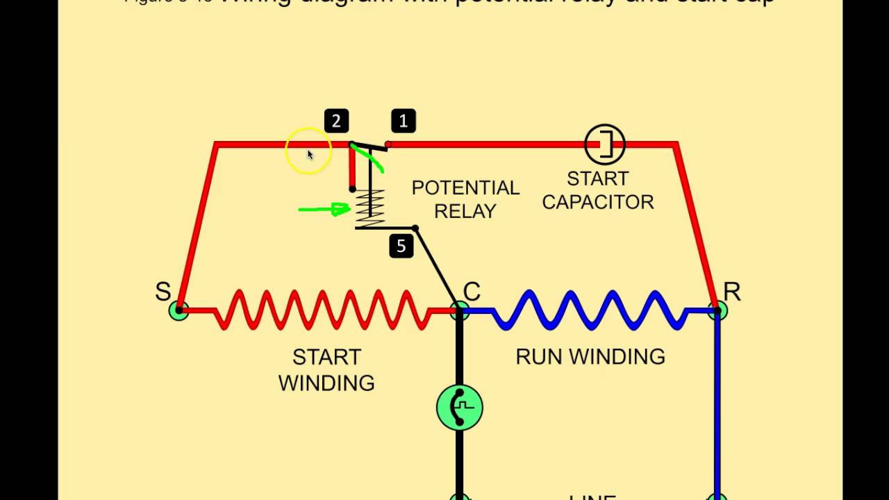
winding with start and run capacitor and potential relay. A Over current thermal protection switch in the terminal box for single-phase ... DWM Copeland semi-hermetic compressors are available for 50 and/or 60 Hz voltage supply. The use of a ... accordance with the position of the capacitors and relay shown on the wiring diagram.

Single Phase Wire Diagrams
Copeland Potential Relay 040 0166 19 Wiring | Wiring Diagram - Potential Relay Wiring Diagram. You are able to often depend on Wiring Diagram as an important reference that may assist you to preserve money and time. With the assist of this e-book, you'll be able to very easily do your own personal wiring tasks.

Copeland Electrical Handbook
If you are looking for copeland potential relay 040 0166 19 wiring you have come to the perfect site. Instructions for wiring a standard automotive relay with descriptions of the pin out and the schematic. This is the wiring of the potential relay. Ribu1c wiring diagram lovely generous potential relay wiring diagram.

Single Phase Compressor Wiring Diagram Auto Electrical Wiring Diagram
The methods to check.CSR motor diagram. Relay - Potential Compressor - Unit Ground Line 1 Line 2 Ground Start Winding Main Winding Control External or Internal Thermal Protector. ... We Provide 20 for you about copeland csr compressor wiring diagram- page 1.Single phase compressor for air-condition - Electrical Engineering Centrewindow ac ...

Types Of Automatic Pumpdown Control Systems Achr News
Hvacrinfo Com

Copeland Cf And Cs Compressor Catalogue Manualzz

E2 Motors And Motor Starting Ppt Video Online Download
Rses Org
Shop 998101465 Cap Relay Copeland Uri
Stareast Com Au

Basic Electrical Controls Of Air Conditioning Units Industrial Controls

Potential Relays What Happened To Terminal 3 Hvac
Icemeister Net
Store Arsnet Com
Rses Org
1
Cpsohio Com
Climate Emerson Com

Pin On Bad Ass Tools

Copeland Semi Herm Soildstate Module
Hvacrinfo Com

55 New Potential Relay Wiring Diagram A Govern Relay Is Used In The Automotive Ind Electrical Circuit Diagram Electrical Wiring Diagram Hvac Air Conditioning
How To Use Relays To Control High Voltage Circuits With An Arduino Projects

10 3 Potential Relays 10 4 Solid State Starting Relays And Devices 10 5 Motor Bearings 10 6 Motor Drives Components For Electric Motors
1
Potential Relays Commercial Refrigeration Online Hvac Training Youtube
Coldco Com
Onlinelibrary Wiley Com

Electrical And Electronics Engineering Air Condition Compressor Potential Relay Wiring
0 Response to "40 copeland potential relay wiring diagram"
Post a Comment