40 8 channel relay board circuit diagram pdf
[Frank D. Petruzella] Programmable Logic Controlle(BookSee.org) H-bridges are available as integrated circuits, or can be built from discrete components.. The term H-bridge is derived from the typical graphical representation of such a circuit. An H-bridge is built with four switches (solid-state or mechanical). When the switches S1 and S4 (according to the first figure) are closed (and S2 and S3 are open) a positive voltage is applied across the motor.
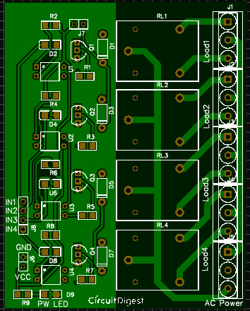
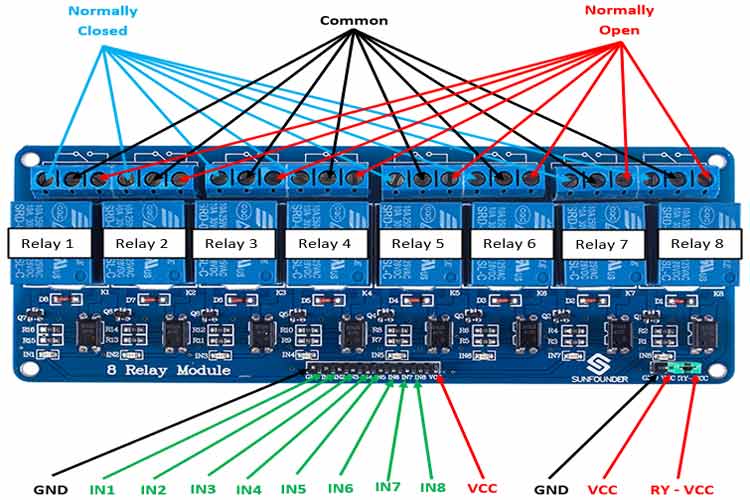
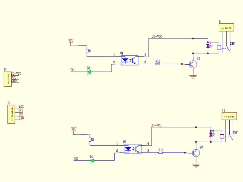
• Each SPDT relay has its own 3-terminal connector. • The A terminal is the COMMON. • The B terminal is the NORMALLY CLOSED (NC). • The C terminal is the NORMALLY OPEN (NO). • The relay’s LED will illuminate when the relay is energised. C NO NC RLY +5V +5V TTL IN COM 0V Electrical circuit diagram for a single relay channel.
8 channel relay board circuit diagram pdf
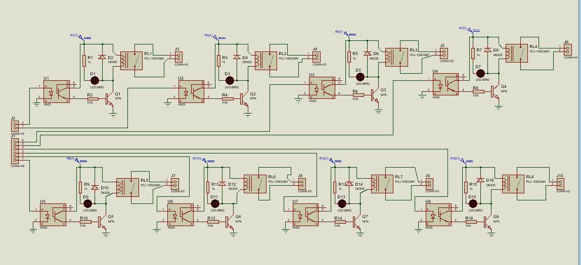
This TI Design provides a complete Programmable Logic Controller (PLC) 8-channel digital input module front-end reference design. TI has designed and fully tested this controller to meet IEC61000-4 Robert L Boylestad - Introductory Circuit Analysis, Tenth Edition The 8 channel relay module has its own optocoupler also called opto-isolator, photocoupler or optical isolator. Optocoupler is a component that transfers electrical signals between two state of isolation circuits by using light, and prevent high voltage from affecting the system receiving the signal. This 8 Channel Relay module can adopt most ...
8 channel relay board circuit diagram pdf. 3. Understanding Timer Delay Relay Function. Understanding all the time delay relay functions available in multifunctional timer can be an intimidating task. During the circuit design with the timer relay and variety of timer configuration, questions such what 8 Channel Relay Board with onboard 5V regulator. This is a general purpose relay board accepting 8 inputs to drive 8 relays providing control requirement in your project. This board can also be used as an add-on card for the various Development board that we provide. 18 Jan 2021 — Internal Circuit Diagram for Eight-Channel Relay Module ... Each relay on the board has the same circuit, and the input ground is common to all ... 20 Mar 2017 — 1 Introduction; 2 Schematic; 3 Principle of relay ... 7.1 For Arduino:; 7.2 For raspberry pi. 8 ... 5V 8-Channel Relay interface board.
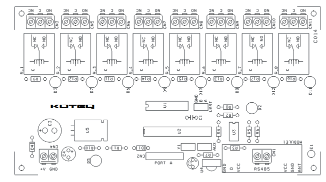
Figure 37: Communication Channel Circuit Diagram 56 Figure 38: Database Documentation of DACS Channels 57. PSRC I5 Schematic Representation of Power System Relaying May 13, 2014 4 1. Scope ... • Single-line diagram (meter and relay single line or one line diagram) MOSFET and JFET circuit symbols P-channel N-channel JFET MOSFET enhancement mode MOSFET enhancement mode (no bulk) MOSFET depletion mode A variety of symbols are used for the MOSFET. The basic design is generally a line for the channel with the source and drain leaving it at right angles and then bending back at right angles into the same direction as the channel. Sometimes … Eight channel remote relay card ... Values on the circuit diagram are subject to changes. ... manual updates, indicated as 'NOTE' on a separate leaflet. This project is a general purpose 8 Channel Relay Board. Description 8 Channel Relay Board is a simple and convenient way to interface 8 relays for switching application in your project. Input voltage level support TTL as well as CMOS. Easy interface with Microcontrollers based projects and analog circuits. Specifications: Input supply 12 VDC @Read More
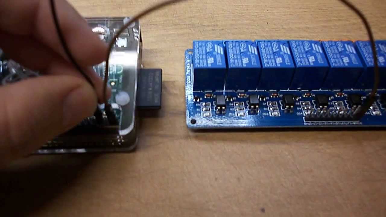
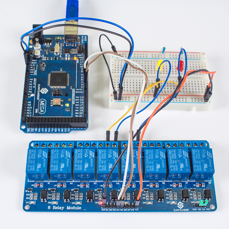
Step 2: TESTING ON BREADBOARD. Now we have all the parts to make a Diy relay module. Now we need to test the circuit diagram of the relay module on a breadboard. don't skip this step , it is necessary to avoid mistakes when soldering into a PCB and check if it is works. 25.01.2021 · Solid State Relay (also known as SSR, SS Relay, SSR relay or SSR switch, solid-state contactor, power electronic switch, automotive relays, electronic power relays, and electrical signal contactors) is an integrated contactless electronic switch device that is compactly assembled from an integrated circuit (IC) and discrete components. ... 01.11.2021 · EEP - Electrical engineering portal is study site specialized in LV/MV/HV substations, energy & power generation, distribution & transmission 12.05.2018 · Hoffman AB763 - Two Channel - PDF layout diagram and Schematic Hoffman AB763 - Two Channel - PDF BOM Hookup notes for Hoffman Boards Hoffman Board Install Instructions Hoffman Turret Boards are located on this page Kits and parts list for this build are here Go here to ask questions about this board You can see my AB763 project on this page Image showing how to create one …
4 Channel Relay Driver Circuit And Pcb Design
4 Channel 5V Optical Isolated Relay Module This is a LOW Level 5V 4-channel relay interface board, and each channel needs a 15-20mA driver current. It can be used to control various appliances and equipment with large current. It is equipped with highcurrent relays that work under AC250V 10A or DC30V 10A. It has -
8 Channel Rs485 Relay Board Electronics Lab Com
40 Limit Pinion, 8 tooth 41 Capacitor 42 Capacitor Clamp 43 Screw, #10-24 x 1/2”, Slot HH Sf-Tap 44 Nut, #10-32, Hex Serrated Flange 45 Circuit Board 46 C.B. Bracket 47 Circuit Board Mount 48 Screw, #10-16 x 5/8”, HH Sf Tap 49 Top Gear Housing 50 Middle Gear Housing 51 Bottom Gear Housing 52 Drive Shaft Bushing 53 Drive Thrust Washer 54 ...
How To Home Automation Connect 8 Channel Relay Raspberry Pi Youtube
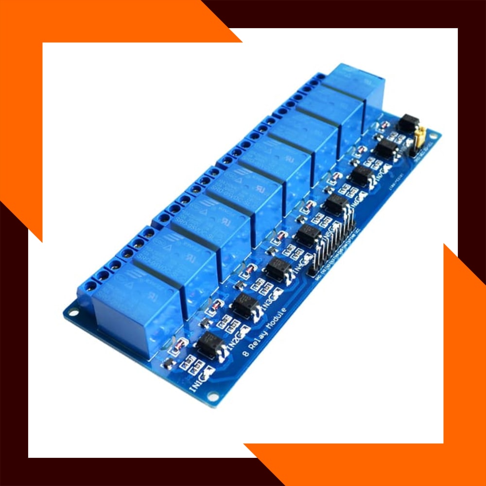
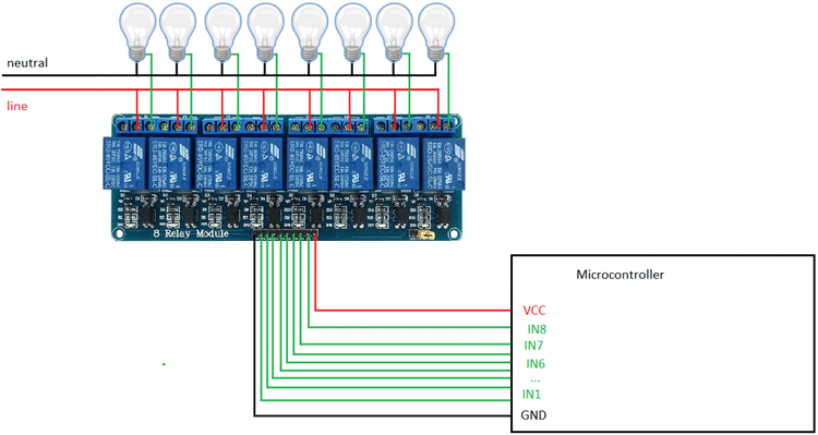
8 Channel 5V Optical Isolated Relay Module This is a LOW Level 5V 8-channel relay interface board, and each channel needs a 15-20mA driver current. It can be used to control various appliances and equipment with large current. It is equipped with high-current relays that work under AC250V 10A or DC30V 10A. It has

8 Channel Home Automation System In Hindi
The 8 channel relay module has its own optocoupler also called opto-isolator, photocoupler or optical isolator. Optocoupler is a component that transfers electrical signals between two state of isolation circuits by using light, and prevent high voltage from affecting the system receiving the signal. This 8 Channel Relay module can adopt most ...
Bisa Cod Modul Relay 8 Channel 5v Optocoupler Arduino Lazada Indonesia
Robert L Boylestad - Introductory Circuit Analysis, Tenth Edition
8 Channel 5v Relay Module Wiki
This TI Design provides a complete Programmable Logic Controller (PLC) 8-channel digital input module front-end reference design. TI has designed and fully tested this controller to meet IEC61000-4
5 Volt 8 Channel Relay Device With 4n25 Hackaday Io
5v 8 Channel Relay Module Pinout Features Working Applications Datasheet
8 Channel Relay Board
2

Raspberry Pi 8 Relay Channel Extension Board With Onboard Led For Raspberry Pi 4 Model B 3b 3b For Smart Home Demo Board Accessories Aliexpress
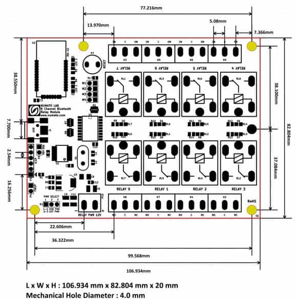
8 Channel Bluetooth Relay Module Numato Lab Help Center

Schematic For 1 Channel Relay Module Projects Kicad Info Forums
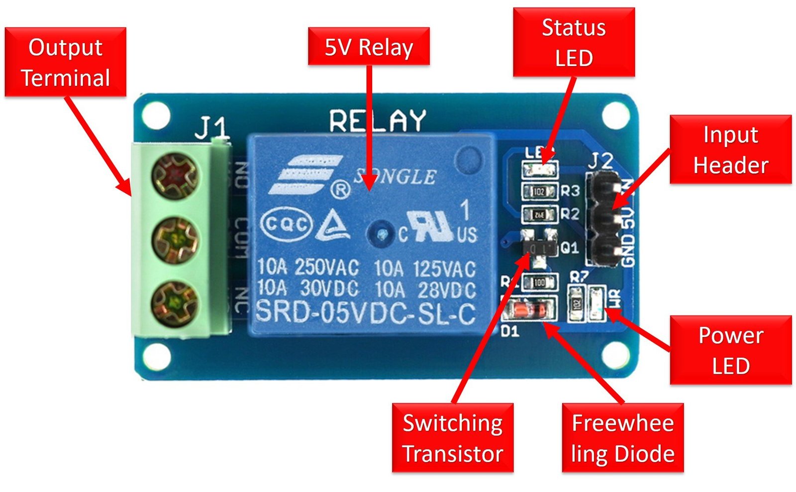
5v Single Channel Relay Module Pinout Working Interfacing Applications
5v 8 Channel Relay Module Pinout Features Working Applications Datasheet

Basics Project 086c Raspberry Pi 3 Model B Board Esp8266 Esp 12e Module 8 Channel Relay Module 7 At Acoptex Com Acoptex Com

Arduino Project Tiny Relay Shield
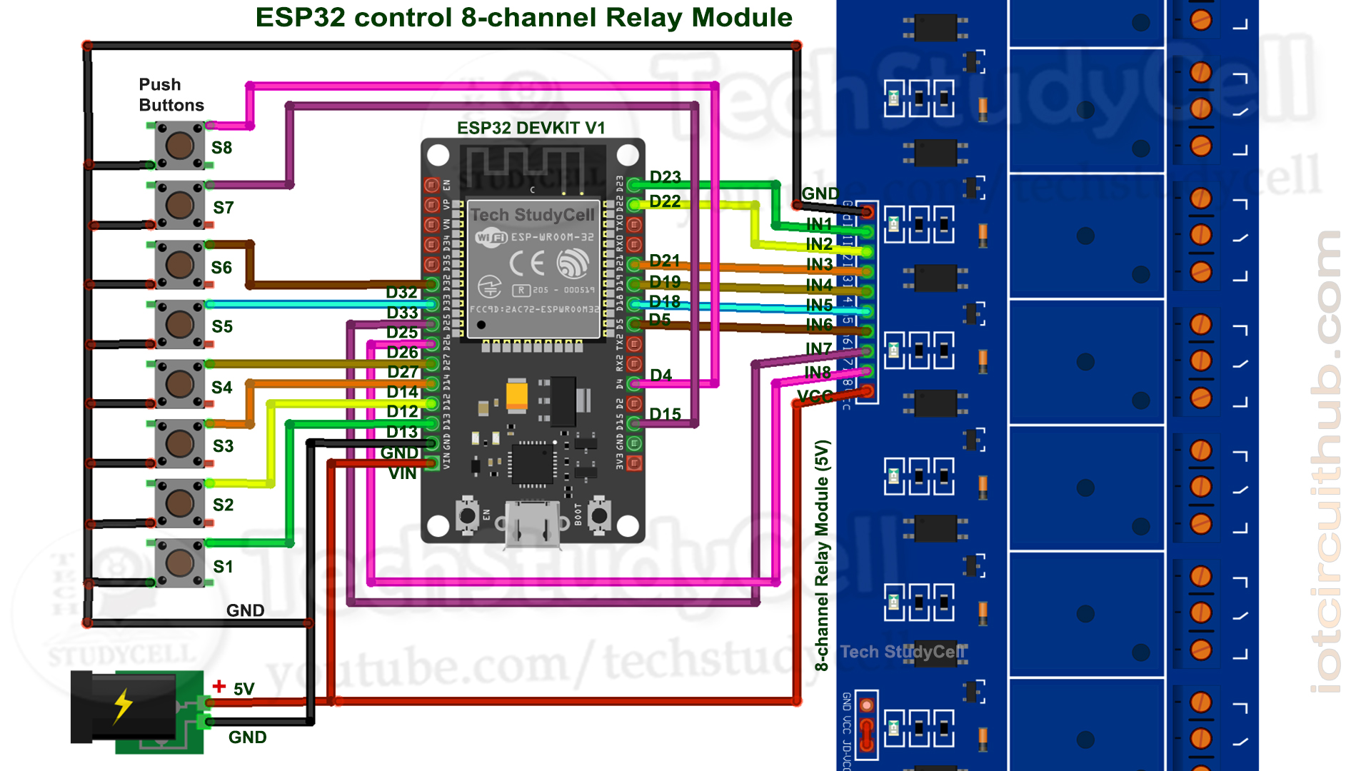
Home Automation System Using Blynk Esp32 Iot Project 2021 Hackster Io

5v 1 Channel Level Trigger Optocoupler Relay Module For Arduino Youtube

Grove 8 Channel Solid State Relay Seeed Wiki

Modul Relay Arduino Pengertian Gambar Skema Dan Lainnya Aldyrazor Com
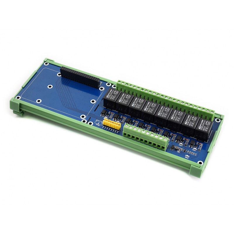
Raspberry Pi Expansion Board 8 Ch Relays

8 Channel Relay Module 10a
8 Channel Lpt Relay Board Electronics Lab Com
4 Channel Relay Driver Circuit And Pcb Design
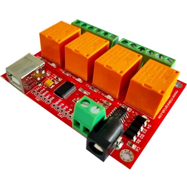
Usb 4 Channel Relay Board
2
3

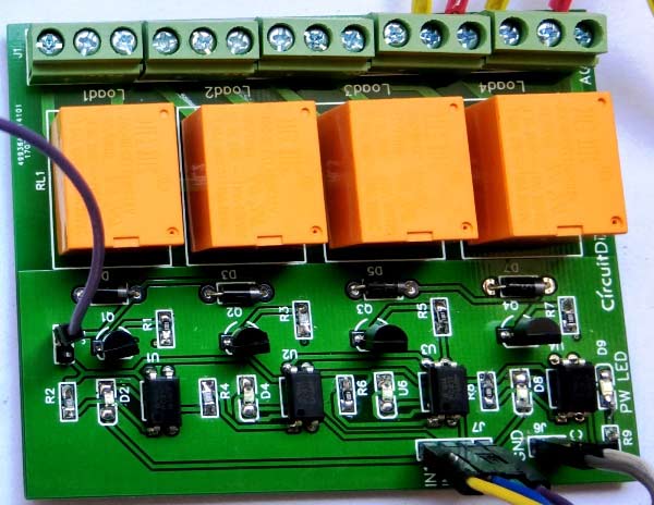
4 Channel Relay Board Buildcircuit Com

12v Relay Board Project Guidance Arduino Forum
Relay Circuit Diagram

8 Channel 5v Relay Module For Arduino Raspberry Pi Sainsmart Com
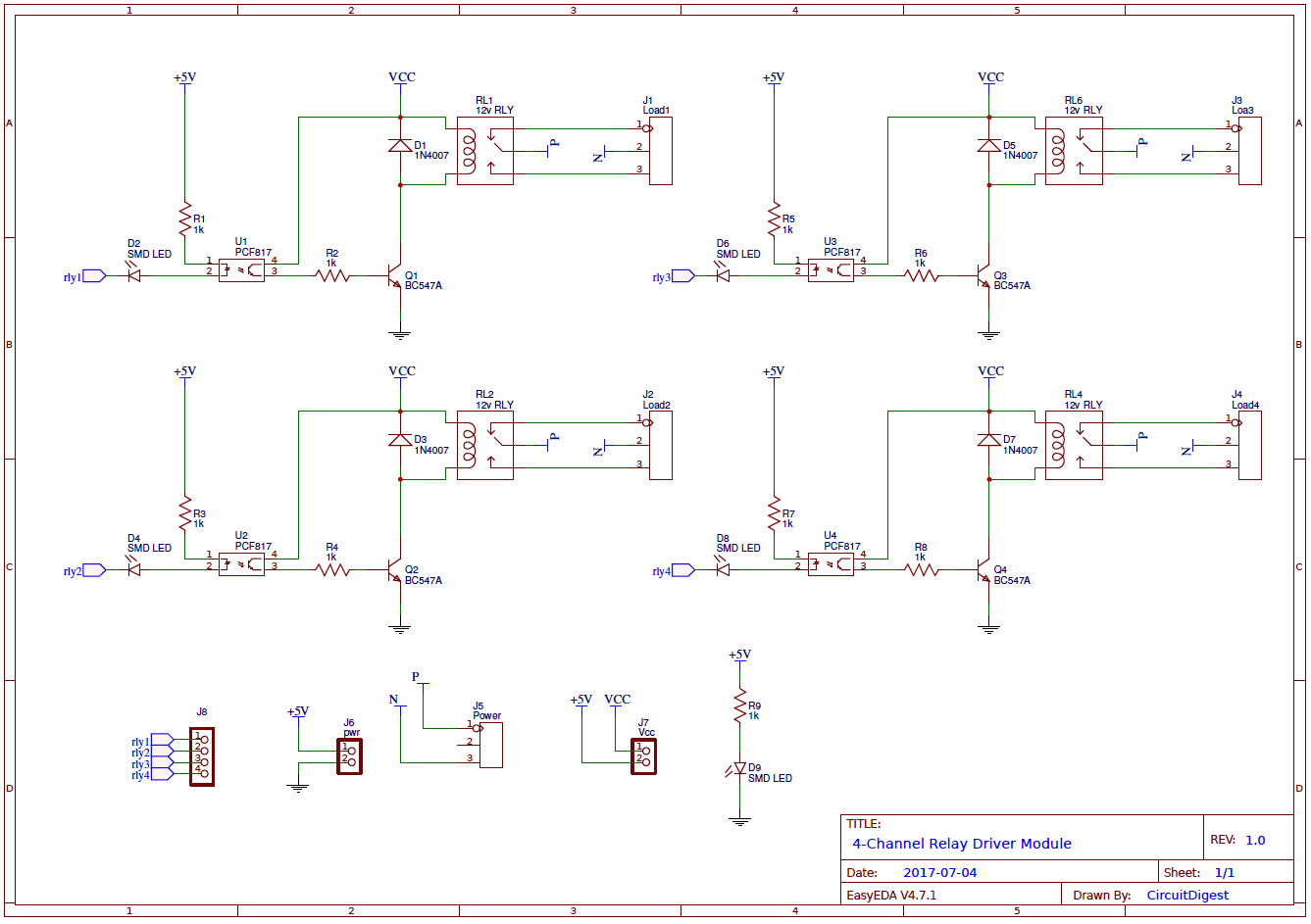
4 Channel Relay Driver Circuit And Pcb Design
Arduino Lesson 2 Channel Relay Module Osoyoo Com
2
2

12v Relay Board Project Guidance Arduino Forum
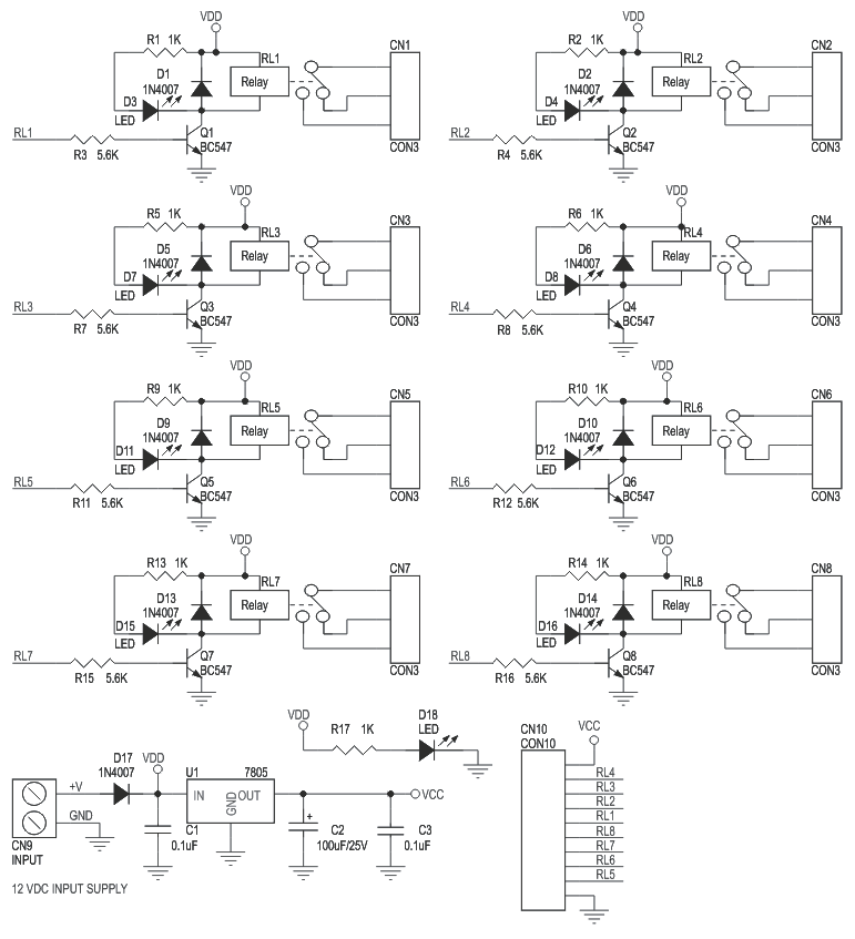
8 Channel Relay Board With Onboard 5v Regulator Electronics Lab Com

4 Channel Relay Board Buildcircuit Com
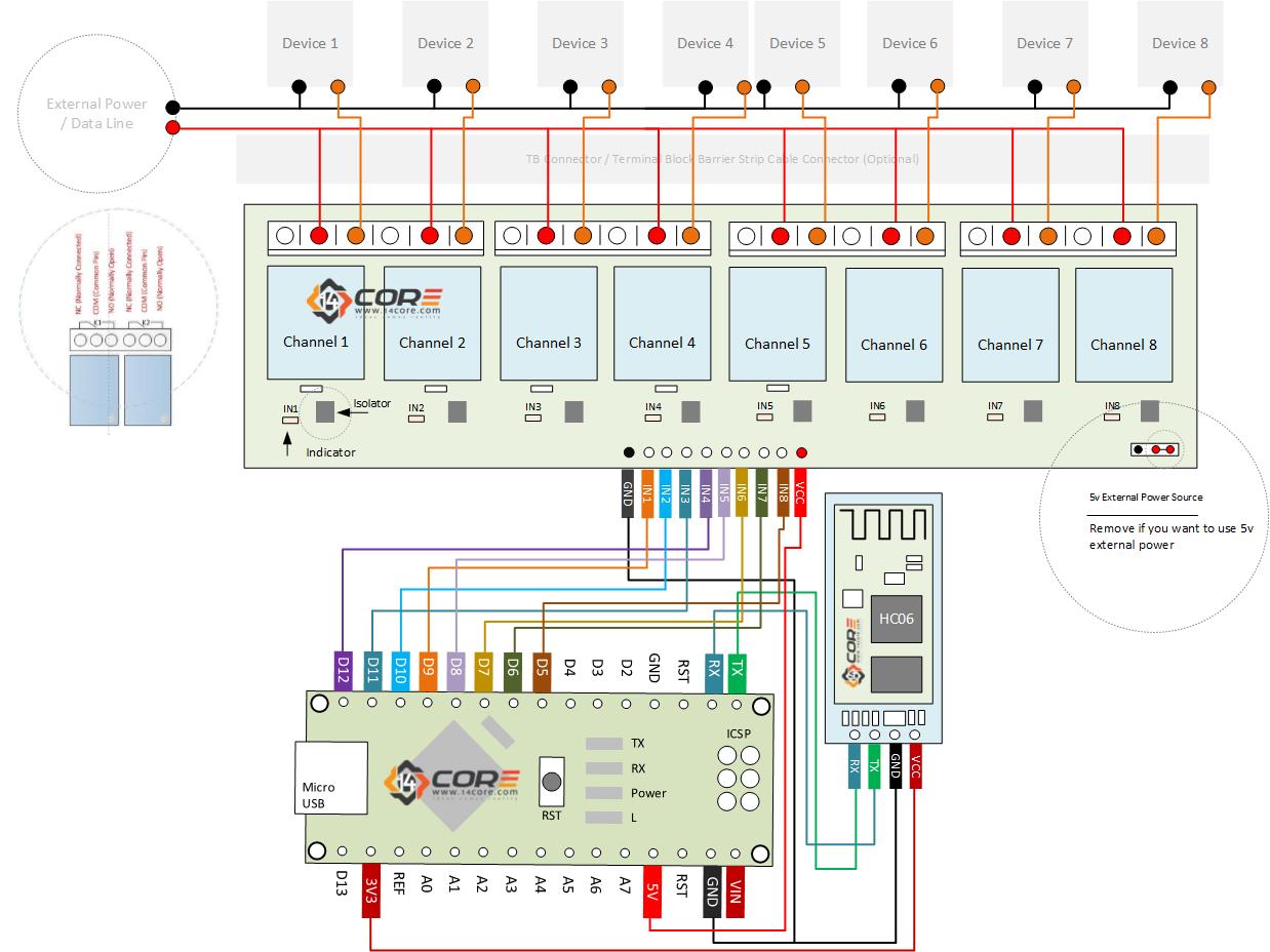
Wiring Bluetooth Hc06 In 8 Channel Relay With Android Arduino Microcontroller 14core Com
0 Response to "40 8 channel relay board circuit diagram pdf"
Post a Comment