39 ph diagram for refrigeration cycle
M. Bahrami ENSC 461 (S 11) Refrigeration Cycle 3 Fig. 5-3: T-s and P-h diagrams for an ideal vapor-compression refrigeration cycle. 1-2: A reversible, adiabatic (isentropic) compression of the refrigerant. The saturated vapor at state 1 is superheated to state 2. wc =h2 − h1 Vapour Compression Refrigeration Cycle. The P-H and T-S diagram for the simple vapor compression refrigeration cycle is shown in the figure for vapour entering the compressor is in dry saturation condition The dry and saturated vapour entering the compressor at point 1 that vapour compresses isentropic ally from point 1 to 2 which increases the pressure from evaporator pressure to condenser ...
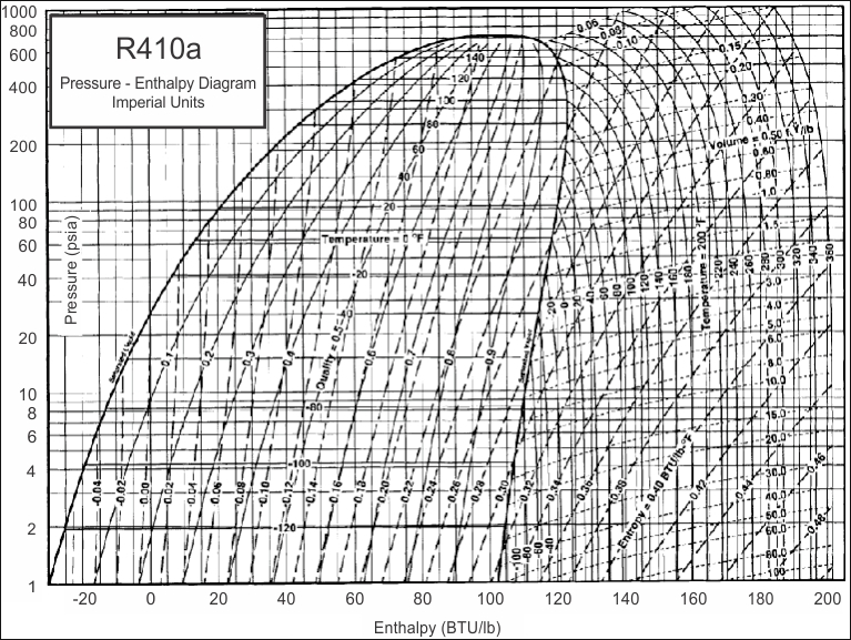
REFRIGERANTS P-H DIAGRAM - Refrigeration - The pressure-enthalpy diagram (log P/h diagram) is a very useful tool for refrigerant technicians, engineers and researchers. Since it's not always possible to have all of these diagrams together, we decided to give you this complete pack.
Ph diagram for refrigeration cycle
2.3 The basic cycle in a log Ph diagram · (1-2): The compression is performed at constant entropy. · (2-3): The condensation is performed at constant pressure and ... The P-H Diagram of the refrigeration cycle with all the operating conditions are as the following: Figure 1-9 P-H Diagram for the Refrigeration System Figure 1-10 Refrigerant Flow Diagram for the Refrigeration System . Practice-2: The CT, ET and TR are the same as Practice-1 Ph diagram for refrigeration cycle. It is an important diagram used frequently for a performance calculation of a refrigerating machine. A sample r 134a diagram is shown below with a sample refrigeration cycle identifying step 1 evaporator step 2 compressor step 3 condenser and step 4 expansion device.
Ph diagram for refrigeration cycle. Download scientific diagram | Pressure-Enthalpy (P-h) diagram of: (a) an ideal refrigeration cycle, (b) a typical refrigeration cycle [5]. from publication: The Effect of Refrigerant Charge and ... R134a Refrigerant Ph Chart. Enthalpy diagram of thermodynamic cycle p h diagram showing the refrigeration p h diagram thermodynamics hvac and thermodynamic scope for two phase fluid lab 3 ph diagram 1 et 102 p h. Pressure Enthalpy Chart Of Rankine Cycle With R134a For First Se Scientific Diagram. The p h diagram of the refrigeration cycle with all the operating conditions are as the following. What is the saturation curve. Figure 4 is a pressure enthalpy diagram of a typical refrigeration cycle in a system with one pound of hfc 134a. It uses for this example evaporating and condensing temperatures of 0f and 120f. Refrigeration cycle in the log p-h diagram. Green = compressor. Red = condenser. Yellow = expansion valve. Blue = evaporator. 1 - 2 polytropic compression to the condensing pressure (for comparison 1 - 2' isentropic compression) 2 - 2'' isobaric cooling, deheating of the superheated vapour. 2'' - 3' isobaric condensation.
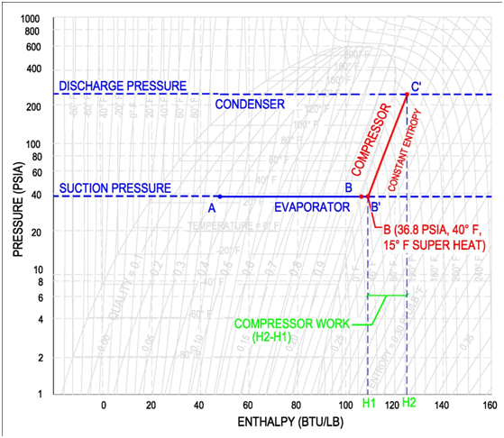
P-H Diagram for Ideal Conditions e . H 1 = h f based on temperature at 'd' (exit of condenser) H 2 = h g based on temperature at 'a' (exit of evaporator) Note 1: If there is super-heating in the evaporator, H 2 can not be obtained from P-H table Note 2: If there is sub-cooling in the condenser, H 1 can not be obtained from P-H table Refrigeration cycle is the basis of all refrigeration systems. So refrigeration cycle should be known to understand the refrigeration system. Some basic refrigeration cycles are discussed here through different diagrams. 2.2 VAPOUR COMPRESSION CYCLE Vapour compression cycle is an improved type of air refrigeration cycle in which a suitable ... Learn how to draw a cycle for ideal conditions on a PH chart.Please provide feedback on this module by selecting "Like" or "Dislike". Your feedback and comme... If you are interested in learning how a refrigeration system works, it is helpful to understand from the Ph (Pressure Enthalpy) chart perspective. It makes our life much easier. This is how the refrigeration cycle diagram looks: Yeah, it seems complicated at first, but it will be easier to understand once I have explained the refrigeration ...
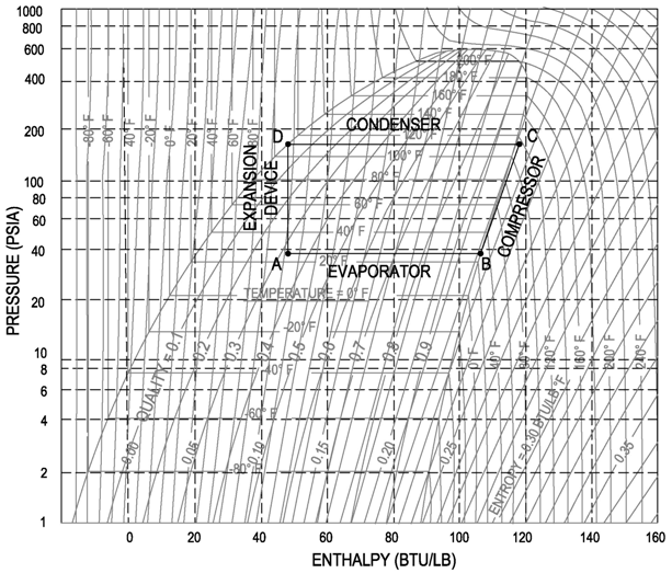
It is recommended that the engineer get a copy of the P-H diagram for R-134a and the other common refrigerants. These diagrams can be found in the ASHRAE Fundamentals book. A sample R-134a diagram is shown below, with a sample refrigeration cycle, identifying (Step 1) Evaporator, (Step 2) Compressor, (Step 3) Condenser and (Step 4) Expansion ... Fig. 11. T-S diagram for Wet Vapour Compression Cycle Fig. 12. P-h diagram for Wet Vapour Compression Cycle In this cycle, enthalpy at state 2 is found with the help of dryness fraction at this point (2). The dryness fraction at points 1 and 2 may be obtained by equating entropies at state 1 and 2. C.O.P = = Ph diagram for refrigeration cycle Efficiency - Working with the Refrigerant Circuit To measure what is happening the first thing to do is to find the temperatures and pressures at key points in the circuit. Measurement points for Temperature T and Pressure P can be used to define the process. The Vapour Compression Cycle, Practical Circuit and ... Figure 2-8: TS and P-H diagram for liquid sub-cooling in a refrigeration cycle. Exercise 2-4: Implement the sub-cooling cycle in Pro II and report the new COP. Compare it with the dry cycle without sub-cooling and the Carnot cycle. Use streams E and F as initial values. The flowsheet has two loops.
Masterclass Refrigeration Cycles Part 3
Learn refrigerant flow in a vapor compression system using a schematic of various components and a pressure enthalpy diagram.
Ptt 251 Thermodynamics For Chemical Engineering Revision Chapter
Learn various states of a refrigerant by drawing a pressure enthalpy chart.Please provide feedback on this module by selecting "Like" or ...

Case 1 The Basics Of Refrigeration Cycle P H Diagram Acirc Euro Ldquo 1 The Basics Of
Refrigeration handbook 1. Basic heat transfer 2. Compression cycle 2.1 The pressure-enthalpy diagram; 2.2 Basic components; 2.3 The basic cycle in a log Ph diagram; 2.4 The complex cycle in a log Ph diagram; 2.5 Other components; 3. Compressors 4. Expansion valves 5. Refrigerants 6. Evaporators 7. Condensers 8.

Pressure Enthalpy Diagram Of The Refrigeration Cycle Refrigeration And Air Conditioning Hvac Repair Hvac Filters
The refrigeration cycle in the log p-h diagram The refrigeration cycle in the log p-h diagram The real refrigeration cycle consists of the following changes of state: 1 - 2 polytropic compression on the condensation pressure (for comparison 1 - 2' isentropic compression) 2 - 2'' isobaric cooling, deheating of the superheated steam

Figure 1 From Energy Performance Of Eco Friendly Re170 And R510a Refrigerants As Alternatives To R134a In Vapour Compression Refrigeration System Semantic Scholar
The refrigeration cycles can also be represented in a P-H diagram. Figure 5: P-H diagram representation of a dry refrigeration cycle Refrigerant fluid choice: We now turn our attention to the fluids. Usually, one tends to pick pL as low as possible, but not below atmospheric pressure. Thus, the refrigerant chosen needs to have a normal boiling ...
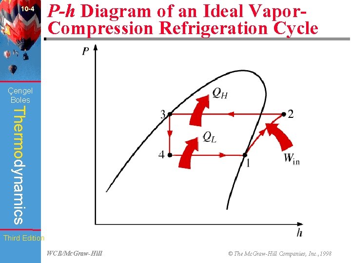
10 Chapter Engel Boles Thermodynamics Refrigeration Cycles Third
P-H Diagram for Ideal Conditions e . H 1 = h f based on temperature at 'd' (exit of condenser) H 2 = h g based on temperature at 'a' (exit of evaporator) Note 1: If there is super -heating in the evaporator, H 2 can not be obtained from P-H table Note 2: If there is sub- cooling in the condenser, H 1 can not be obtained from P-H table

P H Diagrams For Two Stage Refrigeration Cycle A Subcritical Cycle Download Scientific Diagram
Figure 2.9 The real refrigerant cycle in the log P/h diagram. The overheating is the difference between the temperatures at points 1.1 and 1.2. The sub-cooling is the difference between the temperatures at points 3.1 and 3.2. Figure 2.10 Log P/h diagram with temperature levels shown. Figure 2.11 The energy flow in a refrigerant system.

Mechanical Vapour Compression Cycles Heat Exchanger Design Handbook Multimedia Edition
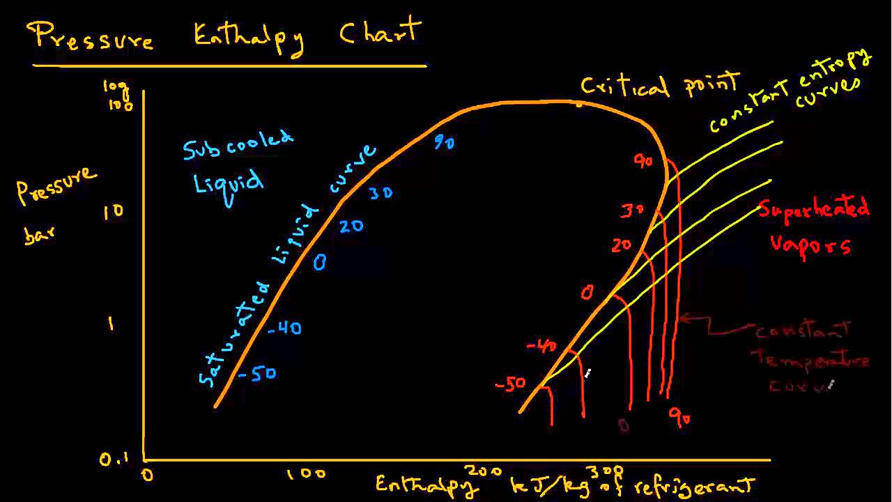
The log p-h diagram shows the thermodynamic state vari- ables in the respective phase. • pressure p. • specific enthalpy h. • temperature T. • specific volume v.
Property Diagrams Ts And Ph For Refrigeration 2 Youtube
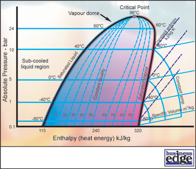
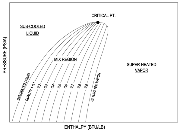
Understanding the basic refrigeration cycle diagram also helps us to find subcooled, superheat and to troubleshoot refrigeration processes much easier. As we can see in the Ph diagram below. Saturation curve this curve represents what state (vapor or liquid) and region (sub-cooled, latent heat, and superheat) the refrigerant is in.

The Refrigeration Cycle
P-h diagram of vapor compression refrigeration cycle Generally, the vapor compression refrigeration system consists of a condenser, an expansion valve, an evaporator, and a compressor.

Refrigeration Cycle Diagram Explained Refrigeration Hvac R And Solar Energy Engineering
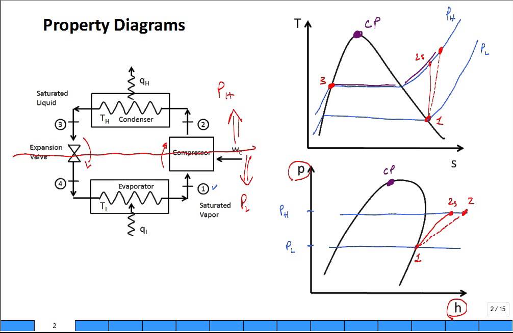
Discuss temperature-entropy (TS) and pressure-enthalpy (PH) property diagrams for vapor compression refrigeration system.
P H Diagram Thermodynamics Hvac And Refrigeration Pe Exam Tools Mechanical And Electrical Pe Sample Exams Technical Study Guides And Tools
Condensers 8. Figure 1-5 Refrigeration Cycle on the P-H Diagram Take the structure image of this refrigeration cycle from Figure 1-5, it becomes the P-H diagram for engineering calculation as shown in Figure 1-6. The points which are required for engineering calculation are from H 1 to H 6 as shown in the Figure 1-6.

P H Diagram Of Vapor Compression Refrigeration Cycle Generally The Download Scientific Diagram
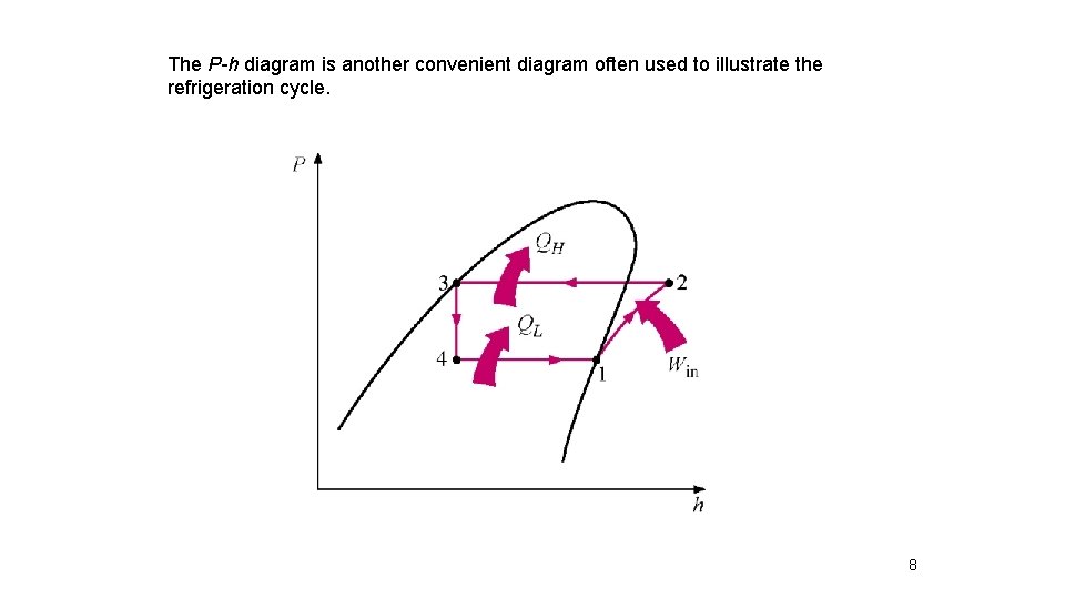
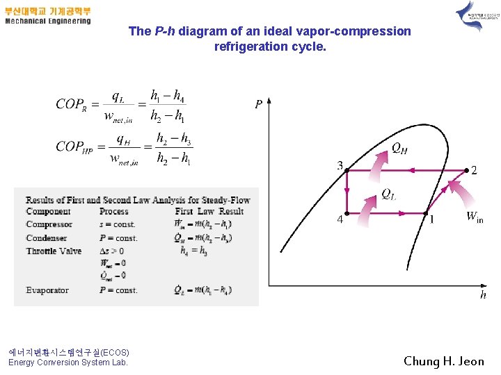
The P-h diagram is another convenient diagram often used to illustrate the refrigeration cycle. The ordinary household refrigerator is a good example of the application of this cycle. Results of First and Second Law Analysis for Steady-Flow Component Process First Law Result Compressor s = const. Wmhh () in =−21
P H Diagram Thermodynamics Hvac And Refrigeration Pe Exam Tools Mechanical And Electrical Pe Sample Exams Technical Study Guides And Tools
The following example is a simplified p-h diagram on which a refrigeration cycle is drawn. Point 1 to 4 show the following. Point 1 to 2: Refrigerant change in a compressor. Point 2 to 3: Refrigerant change in a condenser. Point 3 to 4: Refrigerant change through an expansion valve. Point 4 to 1: Refrigerant change in an evaporator.

Efficiency Measuring Refrigeration
Principles of Refrigeration MAE 554 Professor H. Ezzat Khalifa Syracuse University P-h Chart for R134a (SI Units) ... P-h Diagram for Real Vapor Compression Cycle ... P-h Diagram for 2-Stage VCC with Subcooler. 11 0.6 0.8 1.0 1.2 1.4 1.6 1.8 2.0 2.2 2.4-40 -30 -20 -10 0 10203040 50

B Pressure Enthalpy Diagram For The Refrigeration Cycle Download Scientific Diagram
Ph diagram for refrigeration cycle. It is an important diagram used frequently for a performance calculation of a refrigerating machine. A sample r 134a diagram is shown below with a sample refrigeration cycle identifying step 1 evaporator step 2 compressor step 3 condenser and step 4 expansion device.
Refrigeration Pressure Enthalpy Chart Youtube
The P-H Diagram of the refrigeration cycle with all the operating conditions are as the following: Figure 1-9 P-H Diagram for the Refrigeration System Figure 1-10 Refrigerant Flow Diagram for the Refrigeration System . Practice-2: The CT, ET and TR are the same as Practice-1
Descoenergy Com
2.3 The basic cycle in a log Ph diagram · (1-2): The compression is performed at constant entropy. · (2-3): The condensation is performed at constant pressure and ...
Chapter 11 Refrigeration Cycles 1 2 3 4

Basic Refrigeration Cycle Fundamental Refrigeration
Refrigeration Basics Definitions Part 2
Refrigeration Basics Definitions Part 2

P H Diagrams Of A Typical Refrigeration Cycle And B Subcooled And Download Scientific Diagram

2 1 The Pressure Enthalpy Diagram Swep

Refrigeration Schematic And A Pressure Enthalpy Chart Youtube

Efficiency Measuring Refrigeration
Jsrae Japanese Society For Refrigerating And Airconditioning Engineers
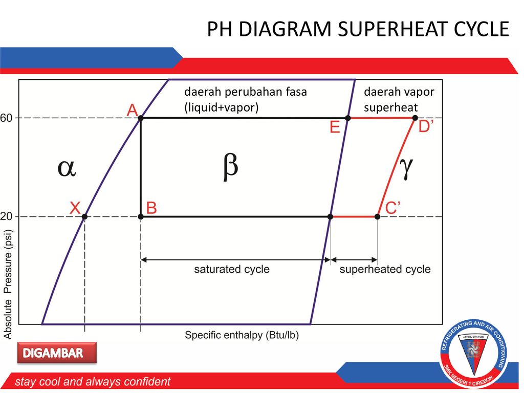
Actual Refrigeration Sistem Pada Ph Diagram Ppt Download
P H Diagram Thermodynamics Hvac And Refrigeration Pe Exam Tools Mechanical And Electrical Pe Sample Exams Technical Study Guides And Tools

Refrigeration

Pressure Enthalpy Diagram For Vapour Compression Cycle Download Scientific Diagram
Solved 2 Question 2 40 Points Refrigeration Cycle Refer Chegg Com

Siklus Refrigerasi Pt Teach Integration

Low Charge And The Pressure Enthalpy Diagram Fundamental Refrigeration
5 Vapour Compression Cycle On Ph And T S Diagrams Lessons Blendspace

Pressure Enthalpy As A Service Tool Achr News

Vapour Compression Refrigeration Cycle On A P H Diagram Download Scientific Diagram
Matec Conferences Org
Ts3040 Files Wordpress Com
0 Response to "39 ph diagram for refrigeration cycle"
Post a Comment