39 iron nickel phase diagram
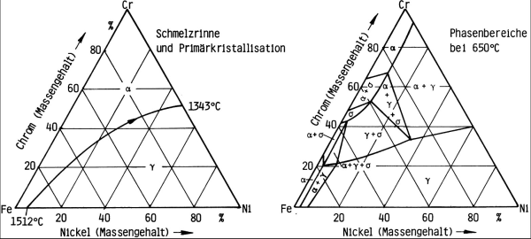
Cr-Fe-Ni (Chromium-Iron-Nickel) Cr-Fe-Ni (Chromium-Iron-Nickel) Raghavan, V. 2008-12-05 00:00:00 JPEDAV (2009) 30:94-95 Section II: Phase Diagram Evaluations DOI: 10.1007/s11669-008-9449-y 1547-7037 ASM International V. Raghavan The detailed review of the early results of the phase (a¢) phases. The Cr-Ni phase diagram [Massalski2] has a equilibria of this system by [1988Ray] presented ... K.C. Hsieh, Y.A. Chang, and T. Zhong: “The Fe-Ni-S (Iron-Nickel-Sulfur) System Above 700 °C,” Bull. Alloy Phase Diagrams, 1982, 3(2), pp. 165–72. ... O. Kubaschewski: “Iron-Sulfur,” Iron—Binary Phase Diagrams, Springer-Verlag, Berlin, 1982, pp. 125–28.
March 11, 2010 - Figure 1 shows the Ni-Pt phase diagram calculated by [2009Lu]. It may be difficult to confirm the phase boundaries of the low-temperature phases experimentally due to the slow process in reaching the equilibrium state. ... Table 1 shows Ni-Pt crystal structure data. ... P. Nash and M.F. Singleton, Ni-Pt (Nickel...

Iron nickel phase diagram
These changes are also applicable to this table as printed in “Fe-Ni (Iron-Nickel)” in Phase Diagrams of Binary NickelAlloys, P. Nash, Ed., ASM International (1991). The correct table is printed in this evaluation in Phase Diagrams of Binary lron Alloys, H. A. Phase Diagrams 1. Iron-Copper System The iron-copper phase diagram, taken from Hansen,3 is presented in Figure 1. Hansen3 also gives a thorough review of the work done on the system up to 1957. A review of more recent work, up to 1963 was done by . Elliott~ The most recent version of the phase diagram The Ti-Si-N-O quaternary phase diagram • Entire phase diagram can be calculated by taking into account all possible combinations of reactions and products • 4 ternary diagrams of Ti-Si-N, Ti-N-O, Ti-Si-O and Si-N-O were evaluated • additional quaternary tie lines from TiN to SiO 2 and Si 2N 2O A.S.Bhansali, et al., J.Appl.Phys. 68(3 ...
Iron nickel phase diagram. Section II: Phase Diagram Evaluations JPEDAV (2010) 31:184-185 DOI: 10.1007/s11669-010-9653-4 1547-7037 ÓASM International Fe-Ni-Si (Iron-Nickel-Silicon) V. Raghavan The review of this system by [1988Ray] presented a an ordered phase FeNi3 (L12, AuCu3-type cubic) forms tentative liquidus projection, partial isothermal sections at congruently from c. The Iowa State University Digital Repository provides free, public access to the research and scholarship of Iowa State's faculty, staff and students. Note: A number of things could be going on here · Please solve this CAPTCHA to request unblock to the website system, the phase diagram usually has the general appearance of that shown in Fig. 3. The diagram consists of two single-phase fields separated by a two-phase field. The boundary between the liquid field and the two-phase field in Fig. 3 is called the liquidus; that between the two-phase field and solid field is the solidus.
March 7, 2017 - Export articles to Mendeley · Get article recommendations from ACS based on references in your Mendeley library July 18, 2012 - Apart of a complex study of the effect of nickel on structure formation in iron-base alloys is presented. An accurate enough phase diagram for alloys of the Fe – Ni system is still lacking. Compilation of the data of some works and subsequent analysis of the known anomalies of structure and ... December 13, 2019 - At low temperatures, the so-called alpha phase (with hexagonal compact crystalline structure) is presented, and the beta phase (with body-centered cubic crystalline structure) emerges above 883°C. Some elements called beta stabilizers, such as niobium, molybdenum, iron, vanadium, and nickel, lead ... by AT Pickles · 1940 · Cited by 16 — The relation of the irreversible changes to the equilibrium phase diagram is not clearly understood. Recently, however, equilibrium diagrams of the iron-nickel ...
Phase Diagrams • Indicate phases as function of T, Co, and P. • For this course:-binary systems: just 2 components.-independent variables: T and Co (P = 1 atm is almost always used). • Phase Diagram for Cu-Ni system Adapted from Fig. 9.3(a), Callister 7e. (Fig. 9.3(a) is adapted from Phase Diagrams of Binary Nickel Alloys , P. Nash The new phase diagram proposed from the results of this work is shown in Figure 4, high temperatures. below 500°C and a maxim Ni content of approximately 7 At$ Ni is ... nickel is soluble in alpha-iron-nickel alloys than indicated by the presently accepted diagram. by V Raghavan · 2009 · Cited by 22 — % Al, monoclinic). The Al-Ni phase diagram [1993Oka] shows five intermediate phases: NiAl3 (D011, Fe3C- ... The influence of iron on the solidification behavior can be shown schematically by another pseudo-ternary diagram, adapted from studies of Alloy 718 (Reference 5). Figure 3 shows this diagram, in terms of the trace of the solidification path moving from the y to the y t A,B Laves particles.
Introduction - Microstructures - Cast Irons, High Alloy ...
The effect of Ni on microstructure, elemental partition behavior, γ′ phase solvus temperature, lattice misfit between γ and γ′ phases, and mechanical properties of the Co-8Ti-11V-xNi alloys ...
The Phase Diagram Of Iron – Carbon: Consider A 94 ...
The C-Ni and Al-C-Ni phase diagrams were determined by chemical analysis of alloys saturated with carbon within sealed graphite crucibles. The solubility of carbon in nickel over the temperature range 1550 °C to 2300 °C is given by log (at. pct C)=2.0376−1874.68/T, where T is temperature ...
Metals Suitable for Enameling - Ganoksin Jewelry Making Community
In Vol. 12, No. 3, page 301 ("The Fe-Ni (Iron-Nickel) System," by L.J. Swartzendruber, V.R Itkin, and C.B. Alcock), in Table 6 three figures contained incorrectly placed decimal points. In the first line following the subhead "bcc phase," 11 736.4 should be 127 364. In the first line following the subheading "fcc phase," 11 274 ...

Armor for Field and Tournament (c. 1540/60 with later etching) // Jörg T. Sorg, the Younger, after German, Augsburg, active 1502-1542
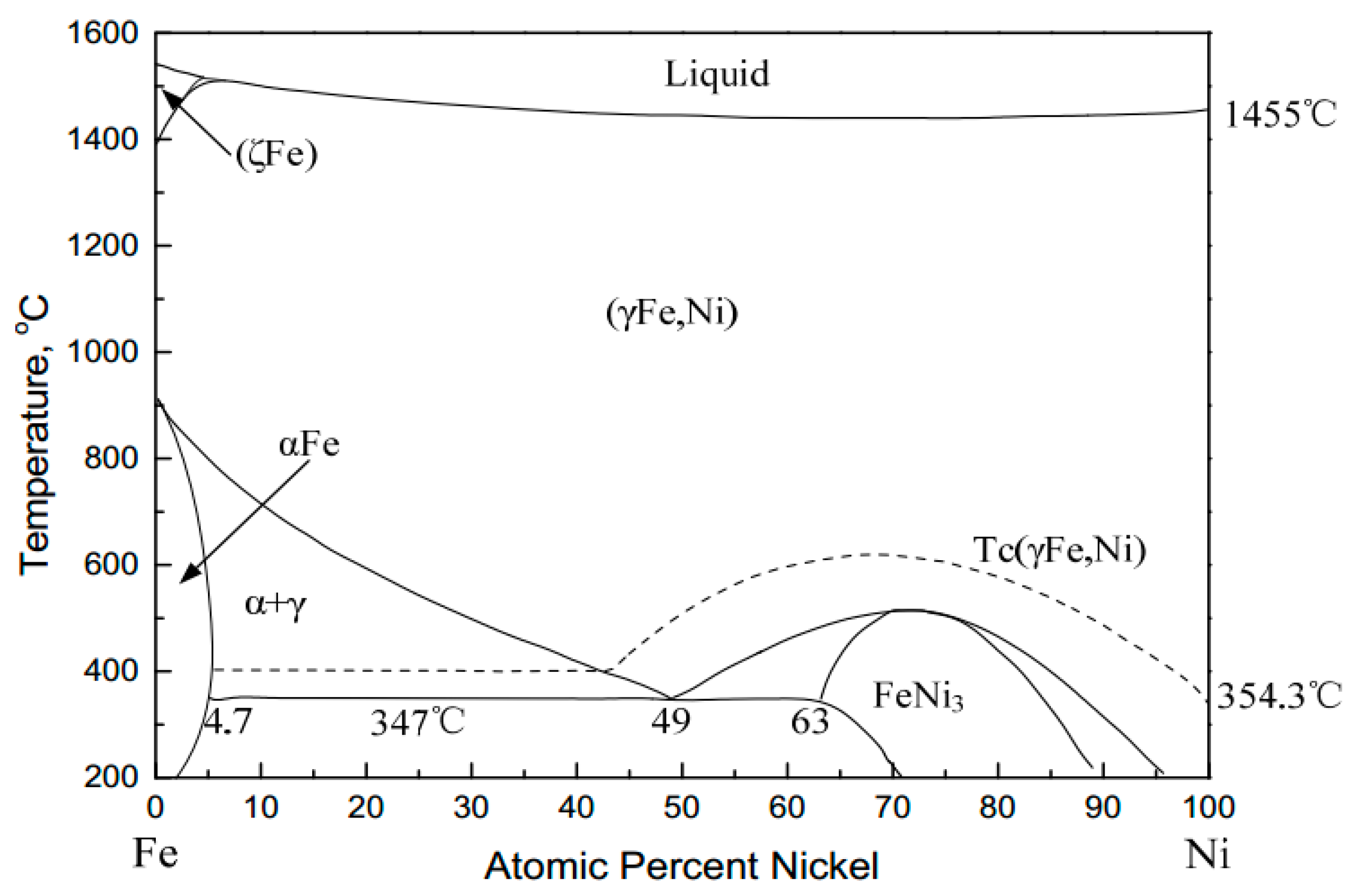
38 Iron-nickel alloys can exist in several crystallographic structures: body-centered-cubic (bcc) 39 structure (α phase), face-centered cubic (fcc) structure (γ phase), and hexagonal close-packed 40 (hcp) structure (ε phase), etc., depending on the pressure (P) and temperature (T) conditions and 41 the nickel concentration (Fig. 1).
Thermodynamics of f.c.c.-Ni–Fe Alloys in a Static Applied Magnetic Field
NTRS - NASA Technical Reports Server · Search · more_vert · About Help · Login · Page not found · Back to Search

Untitled (Carson Pirie Scott & Co. Store, Fenestration) (c. 1955, printed 1973) // Richard Nickel (American, 1928–1972) printed by Patrice Grimbert (French, 1947–1974)
This document is part of Volume 11 `Ternary Alloy Systems: Phase Diagrams, Crystallographic and Thermodynamic Data', Subvolume D `Iron Systems', of Landolt-Börnstein - Group IV `Physical Chemistry'.
Ternary phase diagram overview
About the Foundation · How to Nominate for ASM Awards

Figure 24 from Determination of the iron rich portion of ...
Nickel and iron additions suppress the γ 2, as in Figure 35. When both iron and nickel are present at nominally 5%, the structure of 9-10% aluminium alloys is modified and, instead of the formation of γ 2, a new phase κ (kappa) is created, which is more beneficial. Figure 35 - Cu-Al-Ni-Fe phase diagram at 5% each of nickel and iron (10)
Fe-Ni-O (Iron-Nickel-Oxygen) | SpringerLink
7.1. Al-Fe~Ni PHASE DIAGRAM This phase diagram can be used for the analysis of the phase composition of an 8001 alloy (Table 7.1) that contains only nickel and iron as the alloying elements. This phase diagram is also necessary for the analysis of more complex systems. In the Al-Fe-Ni ternary system, the AlsFe, AlsNi, and AIQECNI phases are
Is nichrome interstitial or substitutional alloy? - Quora
At this temperature, iron is partitioned to the β and transient pyrrhotite phase, which has only a small temperature range of stability before the emergence of pentlandite. Not obvious in these plots but evident in the copper-nickel phase diagram is a tendency to immiscibility in the fcc phase at low temperatures.

woman steaming clothes
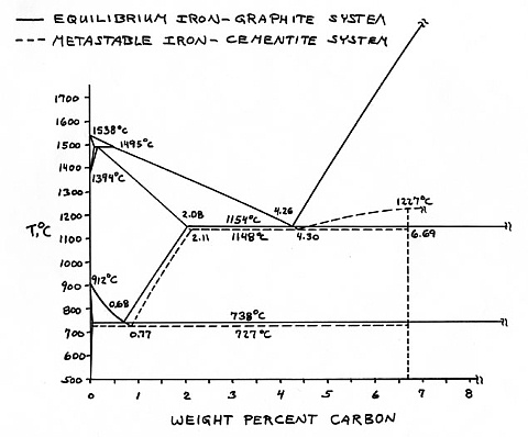
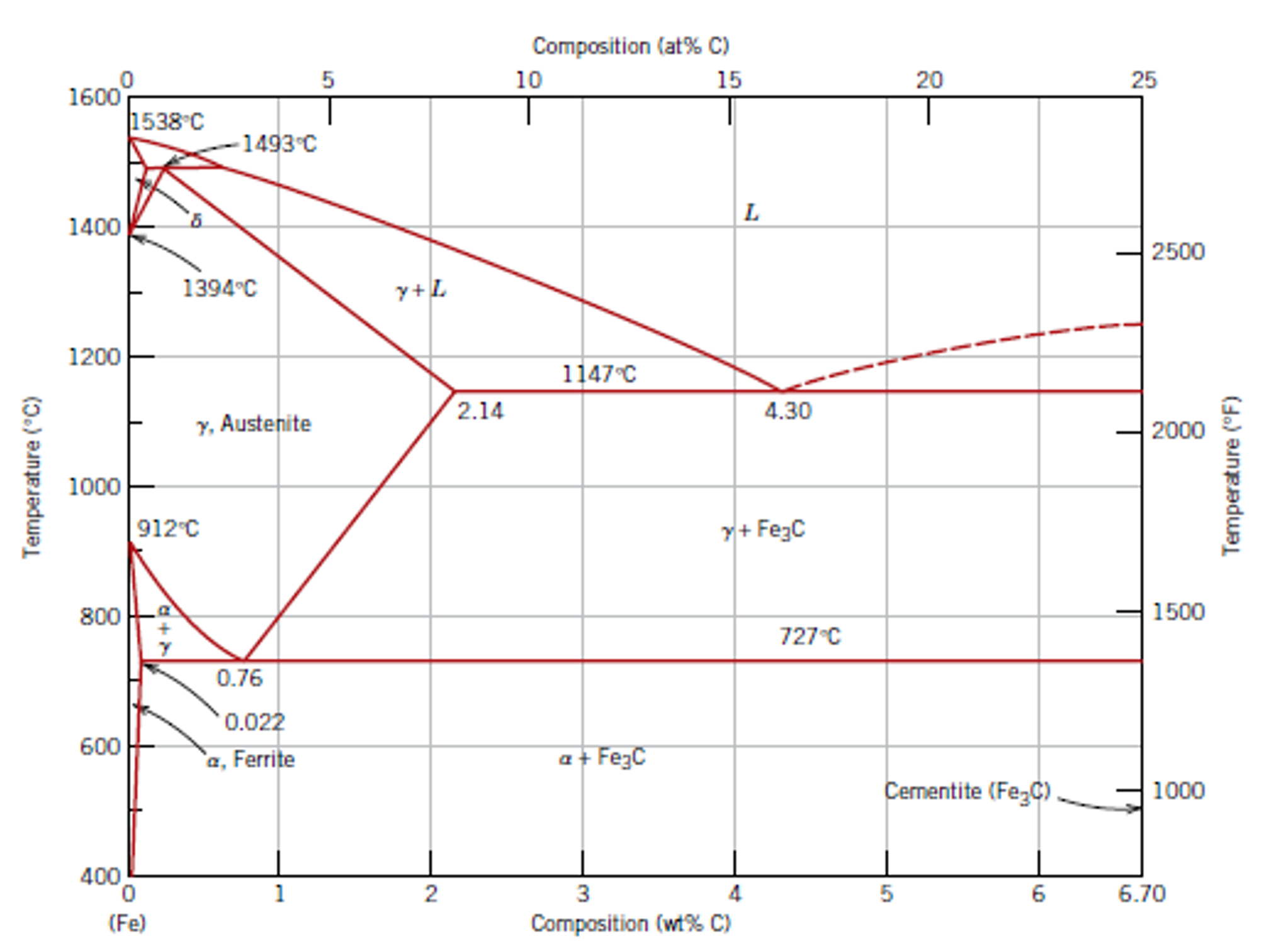
The primary phase of low-carbon or mild steel and most cast irons at room temperature is ferromagnetic α-Fe. It has a hardness of approximately 80 Brinell. The maximum solubility is about 0.02 wt% at 727 °C (1,341 °F) and 0.001% carbon at 0 °C (32 °F). When it dissolves in iron, carbon atoms occupy interstitial "holes". Being about twice the diameter of the tetrahedral hole, the carbon ...
Nickel Oxygen Phase Diagram - Diagram Media
by CW Yang · 1996 · Cited by 194 — Karsten, “The Carbonyl Method and Vapor Deposition for Determining Equilibrium Phases at Low Temperatures Taking Iron-Nickel Alloys as an ...
Binary Phase Diagrams In Metallurgy - MechanicalBase
Equilibrium phase diagram for Iron-Nickel-Chromium alloy ... 1900 1863℃ 1700 1500 1455°C 1300 1345°C (Cr) 1100 ... Effect of chromium and nickel content in steels, for each ...

Диаграмма состояния системы Fe-Ni
Fe-ni phase diagram Alpha and gamma solubility limits in iron-nickel phase diagram at high temperatures - quench- and-anneal and diffusion couple techniques and electron probe microanalysis. Document ID. 19650020214. Document Type. Technical Memorandum (TM) Authors. Goldstein, J. I. (NASA Goddard Space Flight Center Greenbelt, MD, United States)
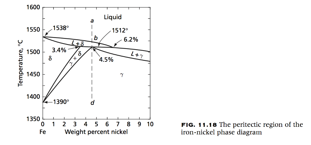
Solved: Consider The Iron‐nickel Peritectic Transformation ...
Representative phase diagram of iron and iron-nickel alloys at high pressures and temperatures. hcp iron is stable over a wide range of pressures and temperatures, while bcc iron is predicted to exist in the inner core (dashed line) and a bcc Fe 0.9Ni 0.1 alloy is experimentally observed at 225 GPa and 3,400 K (hexagon). Melting curves of ...

Image from page 68 of "Bulletin - United States National Museum" (1877)
PHASE DIAGRAM. KEY POINTS OF Fe-C Diagram Phases: ... • Gray iron was the original "cast iron", and is an iron alloy ... • The principal alloying element is 15 to 25% nickel.[1] • Secondary alloying elements are added to produce intermetallic precipitates, which include cobalt,
Solved: Determine the weight percent and composition in weight per... | Chegg.com
[8] Compared to the phase diagram of pure Fe [Hemley and Mao, 2001], it is evident that the stability field of the fcc phase can be extended to higher pressures and lower temperatures with the addition of Ni (Figure 1). However, the effect of Ni on the phase diagram of Fe is not as dramatic as the addition of silicon in Fe [Lin et al., 2002].

woman in black and white floral dress sitting on red plastic stool
Nickel–iron alloys display a broad range of magnetic properties and a well-defined structure in the range from 35 wt % Ni to 80 wt % Ni. A stable random f.c.c. solid solution (? phase) can be obtained above 35 % Ni by choice of annealing temperatures and suitably high cooling rates.

Image from page 59 of "Bulletin - United States National Museum" (1877)
The relation of the irreversible changes to the equilibrium phase diagram is not clearly understood. Recently, however, equilibrium diagrams of the iron-nickel system, determined by means of X-ray data, have been pub-lished by Bradley and Goldschmidt (I939) and Owen and Sully (I939).
Are materials’ properties dependent on temperature? If yes ...
Iron--Nickel--Tungsten Phase Diagram. Showing 1-4 of 25 pages in this report. PDF Version Also Available for Download. Physical Description. 21 p. Creation Information. Winslow, F. R. January 1, 1971. Context ...
Phase Diagrams for Nickel Based Superalloys
Note: A number of things could be going on here · Please solve this CAPTCHA to request unblock to the website

black metal frame glass cross decor
January 1, 1977 - Determination of the iron rich portion of the iron - nickel - carbon phase diagram. ... Determination of the iron rich portion of the iron - nickel - carbon phase diagram.

Untitled (Carson Pirie Scott & Co. Store, Stairway) (c. 1960, printed 1973) // Richard Nickel (American, 1928–1972) printed by Patrice Grimbert (French, 1947–1974)
Using a high-temperature isoperibolic calorimeter, [] determined the partial mixing enthalpy of Ni in ternary melts at 1600 °C across three cross-sections at atom ratios of x Cu /x Fe = 3, 1 and 1/3 for the nickel range of x Ni = -.55.The results were used as inputs for optimization, along with other experimental data on phase equilibria and thermodynamic properties, which included data ...

woman in orange long sleeve shirt sitting on chair
We will limit our discussion of phase diagrams of multi-component systems to binary alloys and will assume pressure to be constant at one atmosphere. Phase diagrams for materials with more than two components are complex and difficult to represent. An example of a phase diagram for a ternary alloy is shown for a fixed T and P below.
Phase Transformation: Lecture Review of Phase Diagrams
Access 130+ million publications and connect with 20+ million researchers. Join for free and gain visibility by uploading your research.

1 a)Aluminum Nickel Phase diagram b)Aluminum Iron Phase ...
Phase Diagram Resources from ASM International. Alloy phase diagrams and crystal structure data are used by metallurgists, materials engineers, and materials scientists to develop new alloys for specific applications; fabricate these alloys into useful configurations; design and control heat treatment procedures for alloys that will produce the required mechanical, physical, and chemical ...

woman ironing clothes
γ-phase alloy and iron is connected to α→ε phase transition in it at pressure 13 GPа. For consideration of the formed contradictions of these data sets we carried out some additional ex-speriment determination of parameters of shock compression of iron and iron-nickel alloy (stainless steel) corresponding to a melting at normal pressure

green pine trees on snow covered ground during daytime
by V Raghavan · 2010 · Cited by 23 — In the Fe-Ni phase diagram, a continuous face-centered cubic (fcc) solid solution (denoted γ) forms between γFe and Ni and is stable over a ...
Phase diagram
For example, in the iron carbon phase diagram, addition of nickel lowers the A3 boundary while the addition of chromium raises it. Eutectic Point. Eutectic point is a point where multiple phases meet. For the iron-carbon alloy diagram, the eutectic point is where the lines A1, A3 and ACM meet. The formation of these points is coincidental.
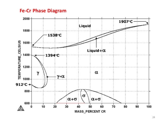
File:Fe-Cr Phase Diagram.gif - Wikiversity
testing and metallographic evaluation. A time-temperature-hardness diagram was prepared for each iron, nickel, and cobalt combination. Scanning electron microscopy was performed to document microstructural features while phase identification was performed using X-ray diffraction and energy

JAIC 1992, Volume 31, Number 3, Article 7 (pp. 355 to 366)
The geometry of the temperature–composition phase diagram of iron–nickel alloys suggests that the hcp–fcc–liquid triple point is located at 10 to 20 wt.% Ni at the pressure of the inner core boundary. The fcc phase could crystallize depending on the nickel and silicon contents in the Earth's core, both of which are fcc stabilizer.
Thermodynamics at the nanoscale: phase diagrams of nickel–carbon nanoclusters and equilibrium constants for phase transitions - Nanoscale (RSC Publishing) DOI:10.1039/C4NR02354D
Download scientific diagram | Fe-Ni phase diagram. [16] from publication: Synthesis by hydrogen reduction and characterization of iron nickel alloys | Iron nickel alloy has been prepared from the mixed aqueous solution of iron and nickel nitrates. In the first step there is a co-formation of ...
Minerals | Free Full-Text | Mineralogical Characteristics ...
The Ti-Si-N-O quaternary phase diagram • Entire phase diagram can be calculated by taking into account all possible combinations of reactions and products • 4 ternary diagrams of Ti-Si-N, Ti-N-O, Ti-Si-O and Si-N-O were evaluated • additional quaternary tie lines from TiN to SiO 2 and Si 2N 2O A.S.Bhansali, et al., J.Appl.Phys. 68(3 ...
Figure 3 from Elastic Properties of Metals and Alloys, I. Iron, Nickel, and Iron-Nickel Alloys | Semantic Scholar
A. Phase Diagrams 1. Iron-Copper System The iron-copper phase diagram, taken from Hansen,3 is presented in Figure 1. Hansen3 also gives a thorough review of the work done on the system up to 1957. A review of more recent work, up to 1963 was done by . Elliott~ The most recent version of the phase diagram
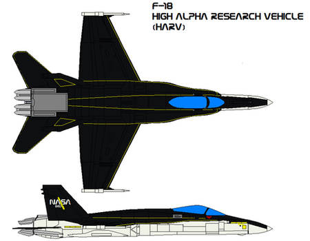
F-18 High Angle-of-Attack
These changes are also applicable to this table as printed in “Fe-Ni (Iron-Nickel)” in Phase Diagrams of Binary NickelAlloys, P. Nash, Ed., ASM International (1991). The correct table is printed in this evaluation in Phase Diagrams of Binary lron Alloys, H.
Neodymium-Iron-Boron Application
![Fe-Ni phase diagram. [16] | Download Scientific Diagram](https://www.researchgate.net/profile/RCs_Navarro/publication/286807012/figure/download/fig3/AS:587504373760005@1517083366669/Fe-Ni-phase-diagram-16.png)
Fe-Ni phase diagram. [16] | Download Scientific Diagram
File:Iron-titanium phase diagram.png - Wikiversity

Representative phase diagram of iron and iron-nickel ...
0 Response to "39 iron nickel phase diagram"
Post a Comment