38 using the isothermal transformation diagram
Using the isothermal transformation diagram. Solution we are called upon to consider the isothermal transformation of an iron carbon alloy of eutectoid composition. Ttt diagram stands for time temperature transformation diagram. A from figure 1022 a horizontal line at 550 c intersects the 50 and reaction completion curves at about 25 and 6 ... About Press Copyright Contact us Creators Advertise Developers Terms Privacy Policy & Safety How YouTube works Test new features Press Copyright Contact us Creators ...
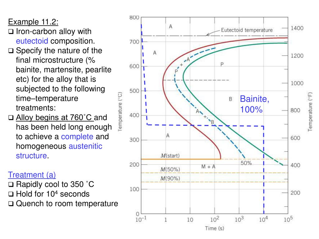
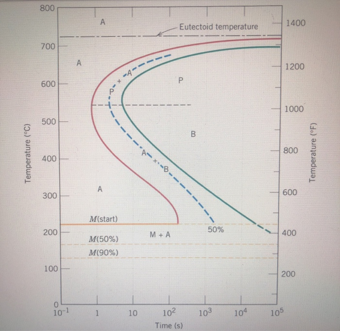
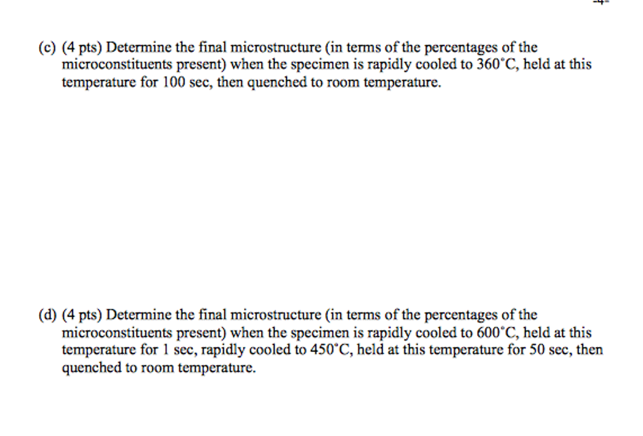
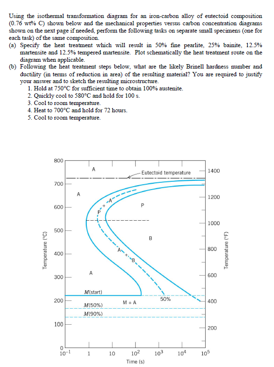
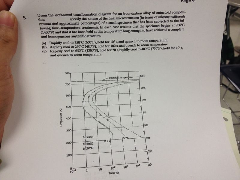
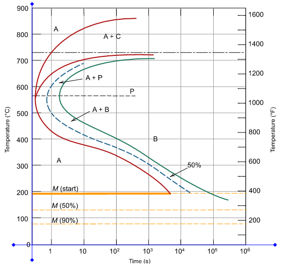
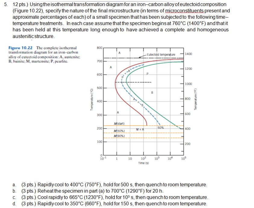
Using the isothermal transformation diagram for an iron-carbon alloy of eutectoid composition (Figure 10.23), specify the nature of the final microstructure (in terms of microconstituents presentand approximate percentages of each) of a small specimen that has been subjected to the following time -temperature treatments. In each case assume ...
Using the isothermal transformation diagram
Isothermal transformation diagrams university of portland isothermal transformation diagrams 10 18 using the isothermal transformation diagram for an ironcarbon alloy of eutectoid position download free and get a copy in your email. 1019 using the isothermal transformation diagram for an iron carbon alloy of eutectoid composition figure 1022 specify the nature of the final microstructure in ... Using the isothermal transformation diagram for an iron-carbon alloy of eutectoid composition. The nature of the final microstructure of the specimen which is subjected to various heat treatment processes can be found out by use of figure 1022 complete isothermal transformation diagram for an iron carbon alloy of eutectoid composition. However, one of the limitations of the diagrams is that the transformations are based on isothermal processes. Heat-treating operations are not carried out using isothermal process, but using continuous cooling. As a result, the TTT curves representing the transformation of austenite are not strictly applicable to heat-treating operations.
Using the isothermal transformation diagram. Using the isothermal transformation diagram for an ironcarbon alloy of eutectoid composition figure 1022 specify the nature of the final microstructure in terms of microconstituents present and approximate percentages of each of a small specimen that has been subjected to the following timetemperature treatments. Using the isothermal transformation diagram for an iron-carbon alloy of eutectoid composition (Figure), specify the nature of the final microstructure (in terms of micro constituents present and approximate percentages of each) of a small specimen that has been subjected to the following time-temperature treatments. 10.18 Using the isothermal transformation diagram for an iron-carbon alloy of eutectoid composition (Figure 10.22), specify the nature of the final microstructure (in terms of microconstituents present and approximate percentages of each) of a small specimen that has been subjected to the following time-temperature treatments. In How we can use isothermal transformation diagrams to predict ahead of time the type of microstructure that we would expect to see if we quench from the Austenite temperature and hold down at a lower temperature? So, here is our isothermal transformation diagram for the Eutectoid Steel composition. We have plotted along the x-axis, the time and ...
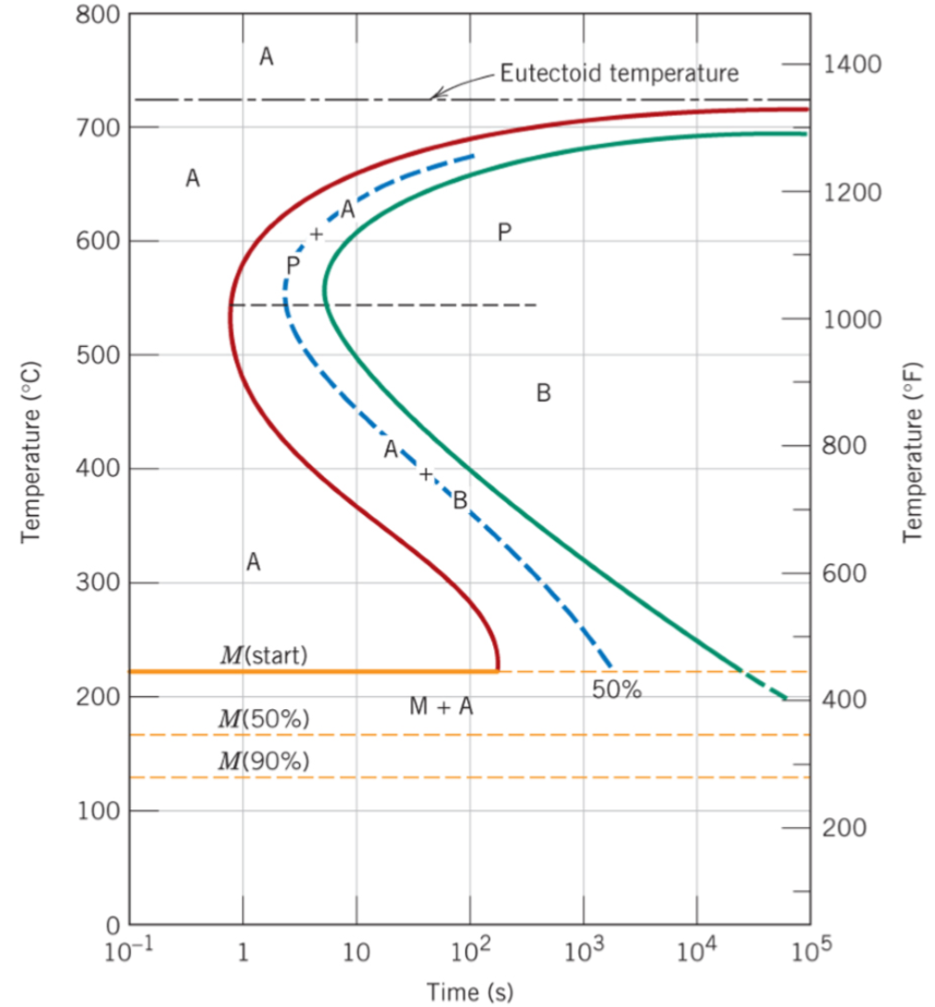
Using the isothermal transformation diagram for an ironcarbon alloy of eutectoid composition figure 1 specify the nature of the final microstructure in terms of microconstituents present and approximate percentages of each of a small specimen that has been subjected to the following timetemperature treatments. The higher the temperature the ... Using the isothermal transformation diagram for an ironcarbon alloy of eutectoid composition figure 1022 specify the nature of the final microstructure in terms of microconstituents present and approximate percentages of each of a small specimen that has been subjected to the following timetemperature treatments. Assignment 2 Solutions. Using the isothermal transformation diagram for an ironcarbon alloy of eutectoid composition shown in the figure describe the final microstructure constituents present and approximate percentages of each of a small specimen that has been subjected to the following timetemperature treatments. These are the times asked for in the problem statement. Isothermal Transformation and Cooling Transformation Diagrams, 1977. Reproduced by permission of ASM International, Materials Park, OH.] Generation of Isothermal Transformation Diagrams • The Fe-Fe3C system, for C0= 0.76 wt% C • A transformation temperature of 675 ºC. 100 50 0 1102 104 T = 675°C y, % transformed time (s) 400 500 600 700 ...
Using the isothermal Transformation Diagram for An Iron-carbon Alloy Of Eutectoid Composition. solved 10 19 using the isothermal transformation diagram 10 19 using the isothermal transformation diagram for an iron carbon alloy of eutectoid position figure 10 22 specify the nature of the final microstructure in terms of microconstituents present and approximate percentages of each of a small ... isothermal transformation are summarized by the isothermal transformation diagram For a given steel austenitized in a particular way, information given by a series of such curves, each determined at a different constant temperature, can be summarized in a single diagram, as illustrated in the lower portion of Fig. 1. Time-Temperature-Transformation (TTT) diagram or S-curve refers to only one steel of a particular composition at a time, which applies to all carbon steels.This diagram is also called as C-curve isothermal (decomposition of austenite) diagram and Bain's curve.The effect of time-temperature on the microstructure changes of steel can be shown by the TTT diagram. Using the animated figure 1022 the isothermal transformation diagram for an alloy of eutectoid composition specify the nature of the final microstructure in terms of microconstituents present and approximate percentages of each of a small specimen that has been subjected to the following temperature treatments.
Using The Isothermal Transformation Diagram For An ...
Using the isothermal transformation diagram for an iron-carbon alloy of eutectoid composition, specify the nature of the final microstructure (in terms of microconstituents present and approximate ...
TTT Diagram Basic - TTT diagram for steel, eutectoid steel
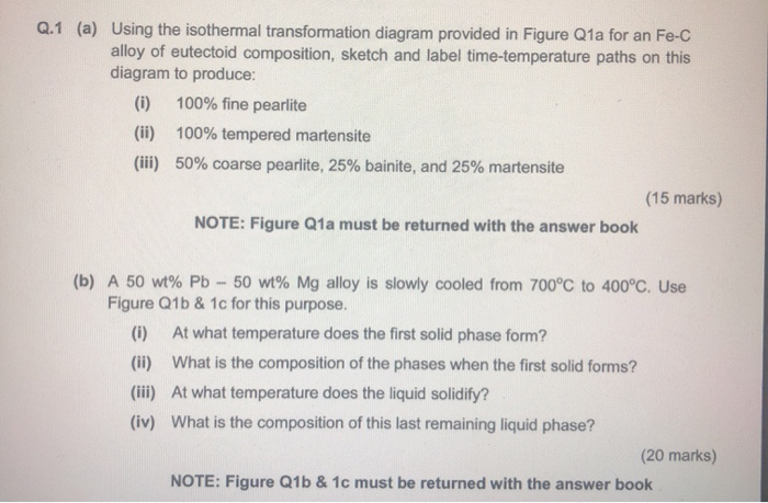
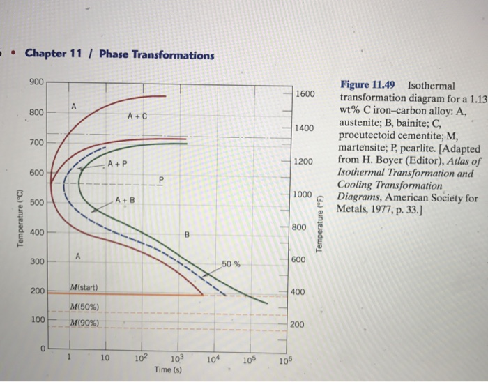
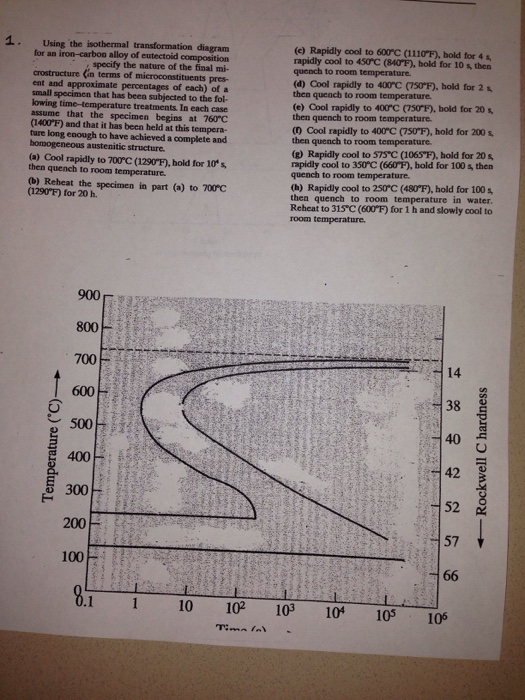
1. (a) Using the isothermal transformation diagram for an iron-carbon alloy of eutectoid composition (Figure 1), specify the nature of the final microstructure (in terms of microconstituents present and approximate percentages of each) of a small specimen that has been subjected to the following time-temperature treatments. In each case assume that the specimen begins at 760°C and that it ...
Answered: Using the isothermal transformation… | bartleby
Using the isothermal transformation diagram for an ironcarbon alloy of eutectoid composition figure 1 specify the nature of the final microstructure in terms of microconstituents present and approximate percentages of each of a small specimen that has been subjected to the following timetemperature treatments.
Solved Using the isothermal transformation diagram for an | Chegg.com
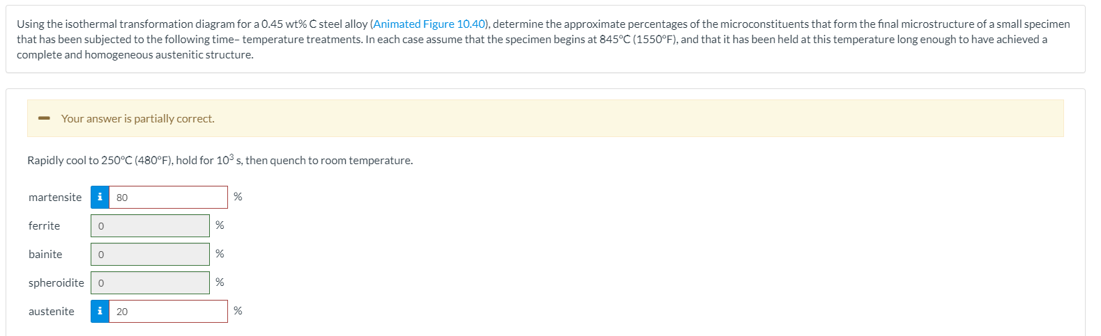
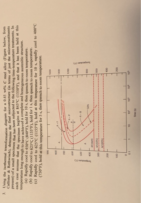
Transcribed image text: Using the isothermal transformation diagram for a 0.45 wt% C steel alloy (Animated Figure 10.40), determine the approximate percentages of the microconstituents that form the final microstructure of a small specimen that has been subjected to the following time-temperature treatments. In each case assume that the specimen begins at 845°C (1550°F), and that it has been ...

ISOTHERMAL TRANSFORMATION DIAGRAM - YouTube
Isothermal transformation diagrams (also known as time-temperature-transformation (TTT) diagrams) are plots of temperature versus time (usually on a logarithmic scale).They are generated from percentage transformation-vs time measurements, and are useful for understanding the transformations of an alloy steel at elevated temperatures.. An isothermal transformation diagram is only valid for one ...

Heat Treating Fundamentals
Using the isothermal transformation diagram for an iron-carbon alloy of eutectoid composition (Figure 10.22), specify the nature of the final microstructure (in terms of micro constituents present and approximate percentages of each) of a small specimen that has been subjected to the following time-temperature treatments.
Isothermal Transformation Diagrams - ppt video online download
T (Time) T(Temperature) T(Transformation) diagram is a plot of temperature versus the logarithm of time for a steel alloy of definite composition. It is used to determine when transformations begin and end for an isothermal (constant temperature) heat treatment of a previously austenitized alloy.
Solved Using the isothermal transformation diagram for an | Chegg.com
Using the isothermal transformation diagram for an iron-carbon alloy of eutectoid composition, specify the nature of the final microstructure (in terms of microconstituents present and approximate percentages of each) of a small specimen that has been subjected to the following time-temperature treatments.
Isothermal Transformation Diagrams
Using the isothermal transformation diagram for an ironcarbon alloy of eutectoid composition figure 1022 specify the nature of the final microstructure in terms of microconstituents present and approximate percentages of each of a small specimen that has been subjected to the following timetemperature treatments. 1018 using the isothermal transformation diagram for an ironcarbon alloy of ...

Using The Isothermal Transformation Diagram (TTT D ...
Using the isothermal transformation diagram. We have plotted along the x axis the time and its in the scale of logarithms and were looking at the temperature on the y axis. Ttt diagram gives 1 nature and type of transformation. Using the isothermal transformation diagram for an iron carbon alloy of eutectoid composition specify the nature of ...

(PDF) Adjustment of Isothermal Transformation Diagrams ...
However, one of the limitations of the diagrams is that the transformations are based on isothermal processes. Heat-treating operations are not carried out using isothermal process, but using continuous cooling. As a result, the TTT curves representing the transformation of austenite are not strictly applicable to heat-treating operations.
Using the isothermal transformation diagram for an iron-carbon alloy of eutectoid composition. The nature of the final microstructure of the specimen which is subjected to various heat treatment processes can be found out by use of figure 1022 complete isothermal transformation diagram for an iron carbon alloy of eutectoid composition.
TTT Diagram Example | Engineering Materials - YouTube
Isothermal transformation diagrams university of portland isothermal transformation diagrams 10 18 using the isothermal transformation diagram for an ironcarbon alloy of eutectoid position download free and get a copy in your email. 1019 using the isothermal transformation diagram for an iron carbon alloy of eutectoid composition figure 1022 specify the nature of the final microstructure in ...
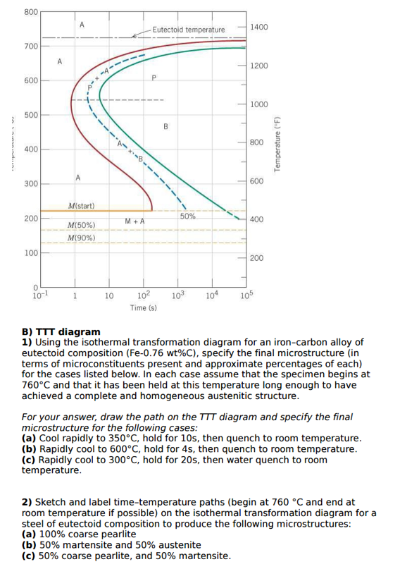
Solved: Q.1 (a) Using The Isothermal Transformation Diagra ...
Solved: Using The Isothermal Transformation Diagram (TTT D ...

B000JWHFFC Atlas of Isothermal Transformation Diagrams | eBay
Using the isothermal transformation diagram for a | Chegg.com
The TTT (isothermal Transformation) Diagram For An ...
Solved: Q.1 (a) Using The Isothermal Transformation Diagra ...
Continuous cooling transformation - Wikiwand
Module 5 Metallic Materials http www tntech edumecoursesZhangModule205M
Using The Isothermal Transformation Diagram For An ...

Solved: The Figure On The Light Shows The Isothermal Trans ...
Isothermal Transformation Diagrams TimeTemperatureTransformation TTT Diagrams Plot temperature
1019 Using the isothermal transformation diagram for an iron carbon alloy of | Course Hero
Chapter 10: Phase Transformations

Using The Isothermal Transformation Diagram - Free Diagram ...
Solved: Using The Isothermal Transformation Diagram For An ...
Solved: 3. Using The Isothermal Transformation Diagram For ...
Solved: Using The Isothermal Transformation Diagram For An ...
Solved: Using The Isothermal Transformation Diagram For An ...
Practical Maintenance » Blog Archive » I-T Diagram and Cooling Curves

An isothermal transformation diagram for a medium carbon ...
Solved: 3. Using The Isothermal Transformation Diagram For ...
Practical Maintenance » Blog Archive » I-T Diagram and Cooling Curves

DIL 805L Quenching Dilatometer
Using The Animated Figure 10.39, The Isothermal Tr ...
Using The Isothermal Transformation Diagram For An ...
0 Response to "38 using the isothermal transformation diagram"
Post a Comment