38 ts diagram carnot cycle
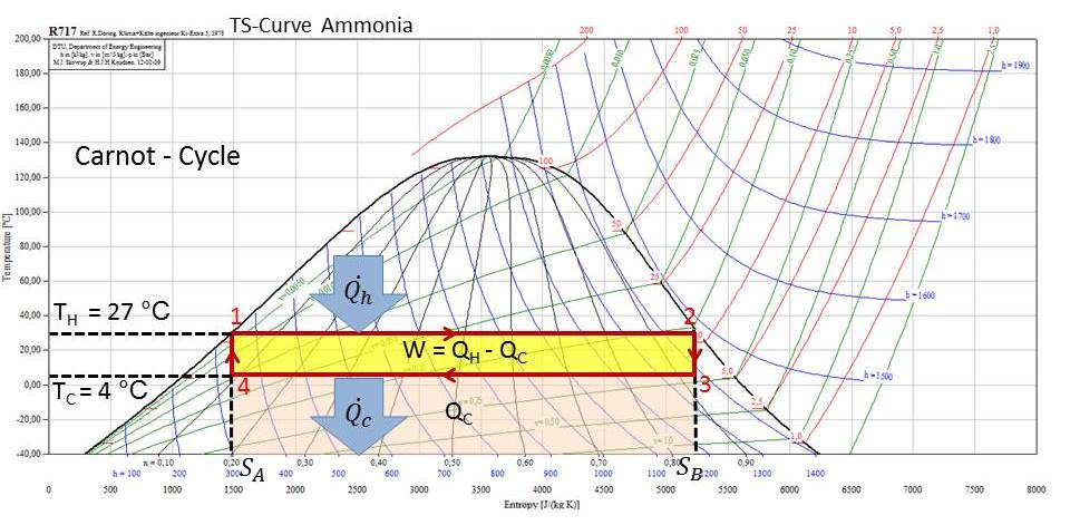
Carnot Cycle. represented on a TS Diagram. = Area below line segment 1-2. = Area below line segment 3-4. Apply the 1st Law to the. Carnot Cycle. : Q H - Q C = W net. Therefore, the area enclosed by the path of a cycle on a TS Diagram represents the net work for the cycle. The Carnot cycle is a theoretical thermodynamic cycle. During this step (A to B on T-S diagram, 1 to 2 P-V diagram) the expanding gas makes.Ts diagram of Carnot cycle. The area under the Ts curve of a process is the heat transferred to the system during that process. The Carnot cycle is often plotted on a pressure- volume diagram (pV diagram ...
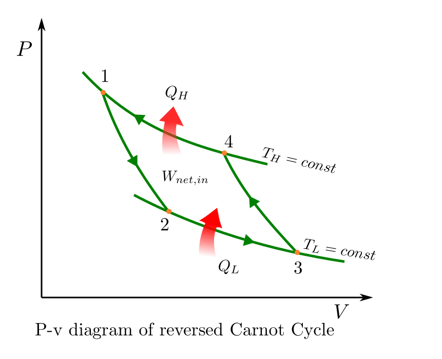
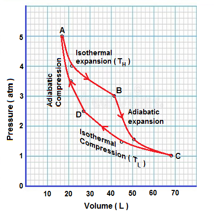
At this point the gas is in the same state as at the start of step 1. Figure 1: A Carnot cycle illustrated on a PV diagram to illustrate the work done.

Ts diagram carnot cycle
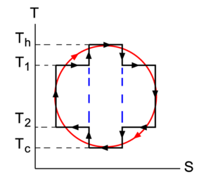
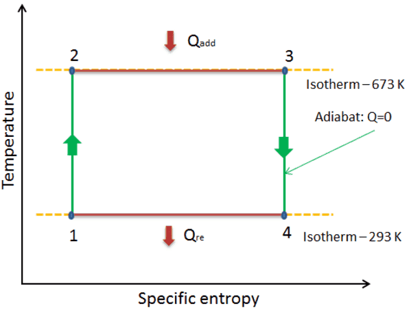
For a Carnot heat pump: From the T-s-diagram, we obtain: Q ab =Q H = T H 2→1. Q zu =Q L = T L 4→3. ΔS 2→1 = – ΔS 4→3. Therefore. For a Carnot refrigerator: For a Carnot heat pump: According to coefficient of performance (COP), we can also draw the following conclusions: The coefficient of performance (COP) of a reversed Carnot cycle ... 5- On a T-s diagram, a vertical line represents an isentropic process (no heat transfer and reversible). The Carnot Cycle. The Carnot cycle is the most ...3 pages ... energy conversion efficiency of a two-reservoir heat engine is generally compared with the theoretical efficiency of the Carnot engine. The Carnot engine ...
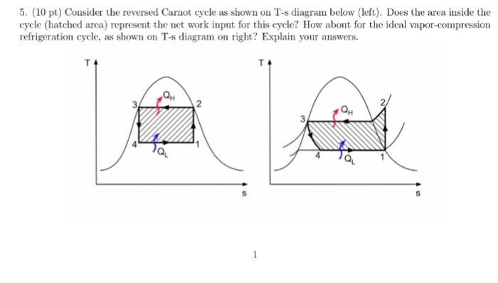
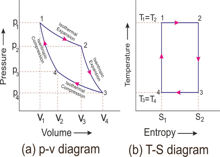
Ts diagram carnot cycle. The Carnot cycle is to be shown on a T-S diagram, and the areas that represent Q_{H}, Q_{L}, and W_{\text {net,out }} are to be indicated.. Analysis Recall that the Carnot cycle is made up of two reversible isothermal (T= constant) processes and two isentropic (s= constant) processes. These four processes form a rectangle on a T-S diagram, as shown in Fig. 7-19. In what follows we discuss one of the most important concepts of thermodynamics, the Carnot cycle. In general in a circular process the thermodynamic system ... pV diagram of Carnot cycle. The area bounded by the complete cycle path represents the total work that can be done during one cycle. The Carnot cycle is ... Carnot Cycle . Q. Q net,in = W net,out. 3 . W net,out L = − QQ HL. Mollier diagram (Table A-10) h-s diagram is useful for analysis of steady-flow devices . 1. wh. S Area Q= S 1 S 2 1 2 Internally reversible process Heat transfer during the internally reversible process ... q Ts= ∆ For isothermal ...
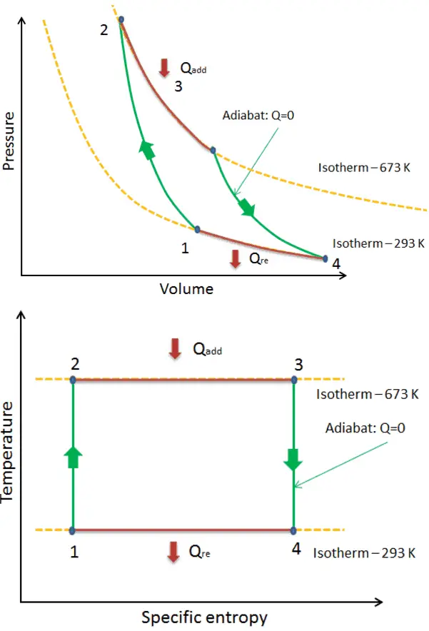
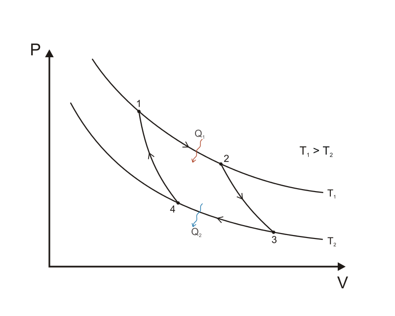
Carnot’s cycle was first developed in the year in 1824 by a French physicist named Sadi Carnot. It is an ideal cycle that basically laid the foundation for the second law of thermodynamics. Carnot cycle also brought up the concept of reversibility. In this lesson, we shall look at all the aspects of Carnot’s cycle as well as understand some ... This cycle is designed by “Carnot” who was the first scientist to analyze the problem of the efficiency of a heat engine, ignoring its mechanical details.He focussed his attention to the basic features of a heat engine. In a Carnot cycle, the working substance is subjected to a cyclic operation consisting of two isothermal and two adiabatic processes. TS diagram for a reversible Carnot cycle. The above diagram represents a graph between temperature T and entropy S for a reversible Carnot cycle. Like the PV diagram, the processes for a TS diagram of a complete Carnot cycle is similar, such as, Line AB = Isothermal expansion, where the temperature T 1 = Constant. Carnot Cycle – pV, Ts diagram pV diagram of Otto Cycle. The area bounded by the complete cycle path represents the total work that can be done during one cycle. The Otto cycle is often plotted on a pressure- volume diagram (pV diagram) and on a temperature-entropy diagram (Ts diagram).
P-V Diagram — The P-V diagram of the Carnot cycle is shown in Figure 2. In isothermal processes I and III, ∆U=0 because ∆T=0.The Carnot Cycle · P-V Diagram · T-S Diagram · Efficiency The Carnot cycle is often plotted on a pressure- volume diagram (pV diagram) and on a temperature-entropy diagram (Ts diagram). When plotted on a pressure-volume diagram , the isothermal processes follow the isotherm lines for the gas, adiabatic processes move between isotherms and the area bounded by the complete cycle path represents the ... ... energy conversion efficiency of a two-reservoir heat engine is generally compared with the theoretical efficiency of the Carnot engine. The Carnot engine ... 5- On a T-s diagram, a vertical line represents an isentropic process (no heat transfer and reversible). The Carnot Cycle. The Carnot cycle is the most ...3 pages

Carnot Refrigeration Cycle Refrigeration Cycle Assignment Help
For a Carnot heat pump: From the T-s-diagram, we obtain: Q ab =Q H = T H 2→1. Q zu =Q L = T L 4→3. ΔS 2→1 = – ΔS 4→3. Therefore. For a Carnot refrigerator: For a Carnot heat pump: According to coefficient of performance (COP), we can also draw the following conclusions: The coefficient of performance (COP) of a reversed Carnot cycle ...

What Is Otto Cycle Pv Ts Diagram Definition

Carnot Cycle Concept How To Derive Efficiency Of Carnot Cycle Animation Pv Ts Diagram Gtu Most Imp Youtube
Chapter 4 Second Law Of Thermodynamics Codecalculation Com 1 Documentation
Solved Consider The Reversed Carnot Cycle As Shown On T S Chegg Com

Rankine Cycle Pdf Pdf Energy Conversion Building Engineering
Carnot Vapour Cycle Processes With P V And T S Diagram
Carnot Cycle Knowino
Carnot Cycle Types Of Processes Nuclear Power
Carnot Cycle Pv Ts Diagram Processes Nuclear Power Com

Carnot Cycle Pv Ts Diagram Processes Nuclear Power Com
4 Stages Of Carnot Cycle Improving Thermal Efficiency Mechanicaltutorial

The Property Diagrams Of Reversible Carnot Cycle A P V Diagram B Download Scientific Diagram

File Carnot Cycle T S Diagram Svg Wikimedia Commons

Objectives Template

Gate Ese Td 21 T S Diagram Carnot Cycle Offered By Unacademy

2 Reversed Carnot Cycle A Schematic Drawing B T S Diagram Download Scientific Diagram

Complete Carnot Cycle Efficiency Pv Diagram Ts Diagram Theorem
Show Four Steps Of Carnot Engine In P V Graph Write The Equation Of Each Step And Obtain The Work Done By The System Also Obtain The Efficiency Of A C
File Carnot Cycle P V Diagram Svg Wikipedia

Vapor And Combined Power Cycles Ppt Video Online Download

Temperature Entropy Diagram Wikiwand
Refrigeration

Difference Between Carnot Cycle And Rankine Cycle Mech4study

A Draw P V Diagram For Carnot Cycle B Write The Name Of Thermodynamic Process Carried Out By Each Part Physics Thermodynamics 12380257 Meritnation Com

What Is Carnot Cycle And Carnot Engine Extrudesign
1

Mechanical Engineering Carnot Cycle

Gas Power Cycles Mech Engineering Thermodynamics Ucl Wiki

Carnot Cycle An Overview Sciencedirect Topics

Carnot Cycle Processes Efficiency Faqs Problems Theorem
Technology

6 A Ideal Carnot Cycle T S Diagram Tmin Download Scientific Diagram

Complete Carnot Cycle Efficiency Pv Diagram Ts Diagram Theorem

Presentation Title Reversed Carnot Cycle Ppt Download

Ch9 Lesson B Page 1 Why Is The Carnot Cycle Impractical

Difference Between Rankine And Carnot Cycle Mechanical Engineering Concepts And Principles
Define Carnot Vapour Cycle Draw The Carnot Vapour Cycle On T S Diagram And Make The Different Thermodynamics Processes Sarthaks Econnect Largest Online Education Community
0 Response to "38 ts diagram carnot cycle"
Post a Comment