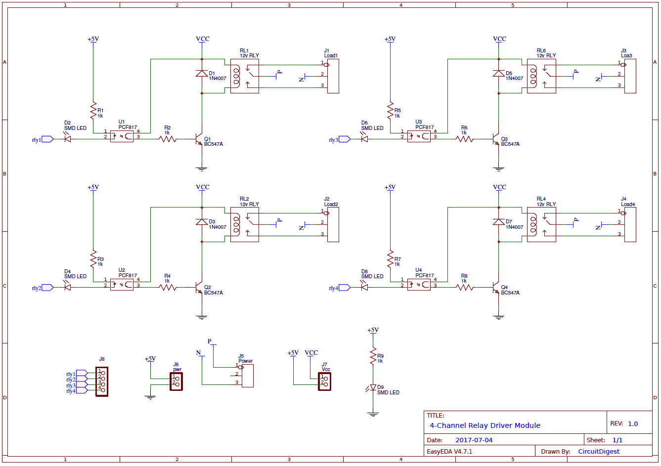
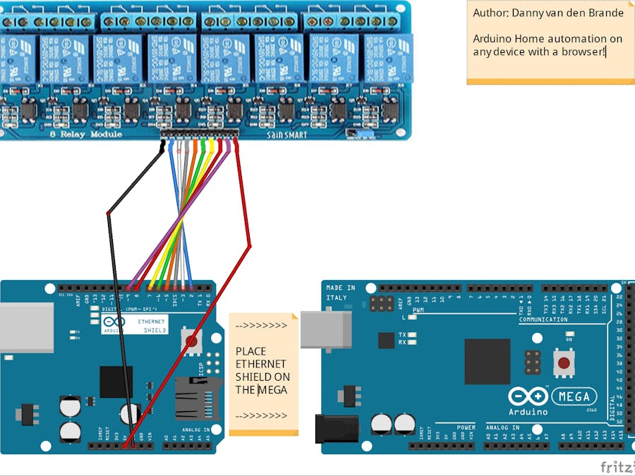
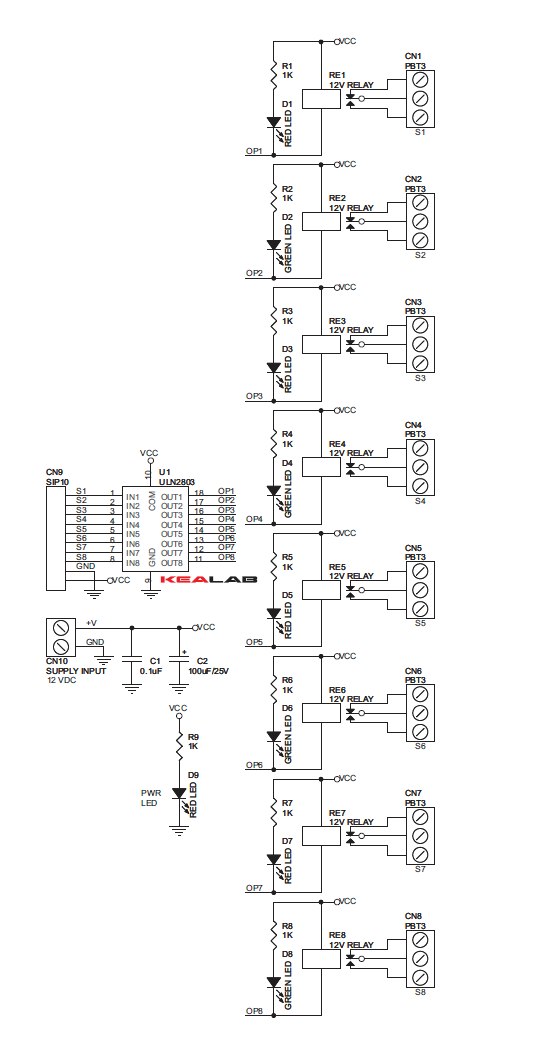
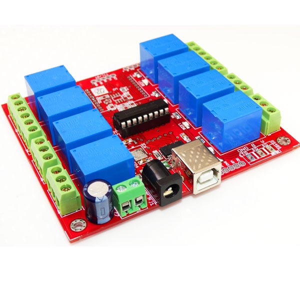
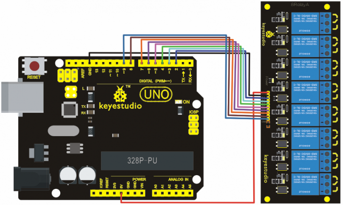
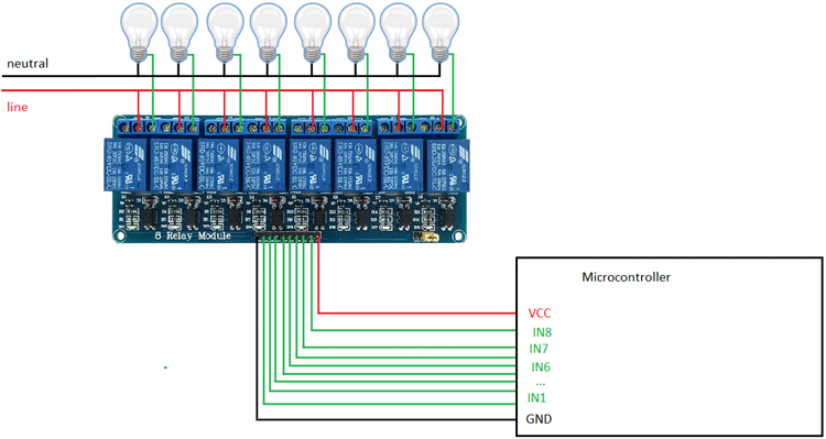
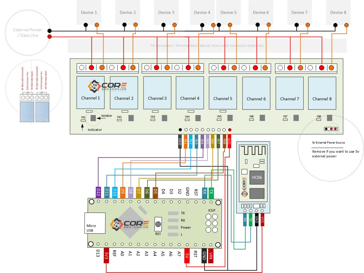
38 8 channel relay board circuit diagram
CES 4.1 & 5 Seagull AS (QUESTIONS & CORRECT ANSWERS Many relays use an electromagnet to mechanically operate the switch and provide electrical isolation between two circuits. This 8 channel 5V relay has both ... Rating: 4.8 · 33 reviews · US$12.99 · In stock
Step 1: Description · Step 2: Specifications: · Step 3: Schematic · Step 4: PCB LAYOUT · Step 5: Parts List · 8 Comments.

8 channel relay board circuit diagram
29 Aug 2015 — The 8 channel relay module has its own optocoupler also called opto-isolator, photocoupler or optical isolator. Optocoupler is a component ... The Serial relay board is with 8 SPDT relays rated up to 7A each. ... Circuit Diagram (8 Channel Relay Board- Serial); Code (Raspberry Pi and Beagle Bone). Rating: 97% · 6 votes 8 Channel Relay Board is a simple and convenient way to interface 8 relays for switching application in your project. Input voltage level support TTL as ...
8 channel relay board circuit diagram. Schematic — This is a 8-channel LOW level trigger relay and it can be applied to Arduino and Raspberry Pi. Relays are suitable for driving high power ... Relay 8 Channel Relay Home Automation ESP8266 Arduino Raspberry Pi Openhab · Default Thumb · 8 Channel Board · Default Thumb Srisivasai Prasanna - 2 years ... 20/04/2015 · This circuit measures the speed of a cricket ball based on the time taken by the ball to travel the distance from the bowling crease to the batting crease [25]. 28. 8 Channel Relay Module Schematic. Page 3. 3 www.handsontec.com. It is sometimes possible to use this relay boards with 3.3V signals, if the JD-VCC (Relay Power) ...8 pages
25/08/2017 · As said they have 4-data bit and 8-addresss bit, these 8 address bits has to be set same on both the encoder and decoder to make them work as a pair. Circuit Diagram of RF Transmitter and Receiver: The complete circuit Diagram including the Transmitter and Receiver part for this project is shown in the images below. 18 Jan 2021 — The eight-channel relay module contains eight 5V relays and the associated switching and isolating components, which makes interfacing with a ... “channels” on the E–Stop). The timing diagram in figure 6, shows the sequence of events when the E–Stop is closed and the reset button is pressed. IEC Diagram A1 T11 T12 T31 T34 T22 T35 13 23 33 43 53 61 73 A2 X1 X2 T33 14 24 34 44 54 62 74 T32 B1 B2 (+) (–) K3 K2 K1 K1 K2 K3 c Channel 1 (T11-T12) Channel 2 (X1-X2) E-Stop Reset Wiring ... 8 Channel Relay Board is a simple and convenient way to interface 8 relays for switching application in your project. Input voltage level support TTL as ...
The Serial relay board is with 8 SPDT relays rated up to 7A each. ... Circuit Diagram (8 Channel Relay Board- Serial); Code (Raspberry Pi and Beagle Bone). Rating: 97% · 6 votes 29 Aug 2015 — The 8 channel relay module has its own optocoupler also called opto-isolator, photocoupler or optical isolator. Optocoupler is a component ...
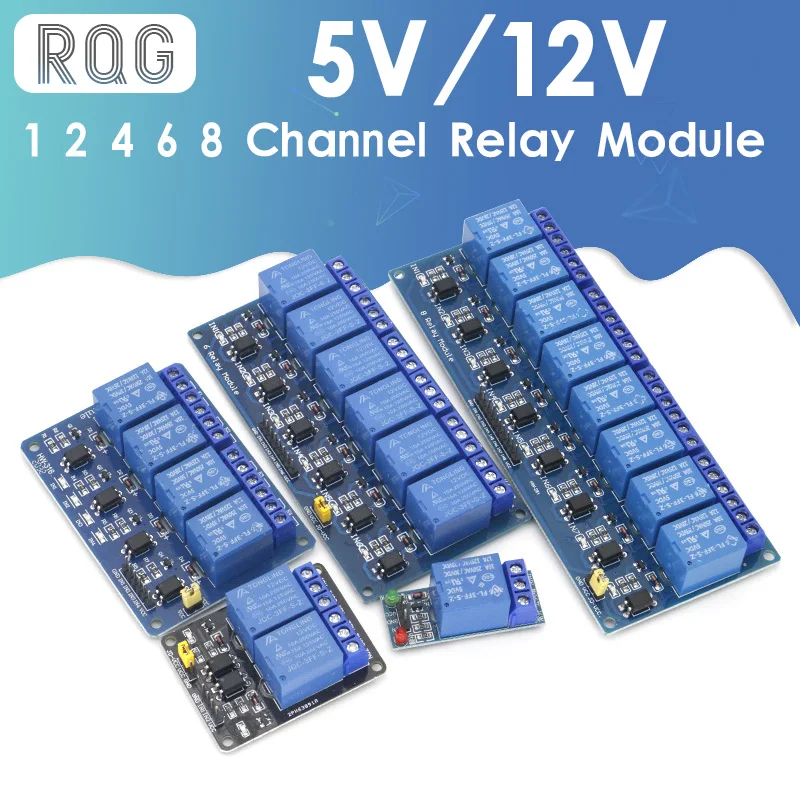
5v 12v 1 2 4 6 8 Channel Relay Modul Dengan Optocoupler Relay Output 1 2 4 6 8 Cara Relay Modul Untuk Arduino Di Saham Relay Aliexpress












0 Response to "38 8 channel relay board circuit diagram"
Post a Comment