37 cummins 8.3 fuel pump diagram
Fuel leak on 8.3. I have an odd problem with a fuel leak on my 8.3 350hp cummins. When it sits for a couple of days and I start it it will drip fuel down from somewhere around the injector pump. When I shut it down and restart it it won't leak. I have looked at it from the top and bottom and can't see a leak anywhere on the pump. Tube Routing: Fuel Pump Side. Attachment Clip Provision: ... diagram number 3925624. Instruments are 12 Volt. ... 350 @ 2100 For 6CTA 8.3 F-1.129 pages
The fuel pump main shaft turns at engine crankshaft speed, and drives the gear pump, governor and tachometer shaft. The location of these units in the fuel pump housing is indicated in Fig. 1-2. GEAR PUMP: The gear pump is located at the rear of the fuel pump and it is driven by the Figure 1-2.

Cummins 8.3 fuel pump diagram
Fuel System Naturally Aspirated I Turbocharged Maximum Allowable Restriction to the Fuel Transfer Pump 75 mm Hg or Filter Head Must Not Exceed 13 in Hol Maximum Allowable Return Line Restriction Must Not Exceed 190.5 mm Hg [7.5 in Hg] Inlet Pressure to the Injection Pump Range 0.00 kPa [0.00 psi] to 39.0 kPa [5.00 psi] Cummins Engine Company, Inc. reserves the right to make changes at any ... System Diagrams . ... The Cummins part number for the fuel injection pump.115 pages 26 Apr 2020 — (A visual inspection of the passenger side of the engine (Google diagrams of your era's engines, and they should point to the Lift Pump.) ...
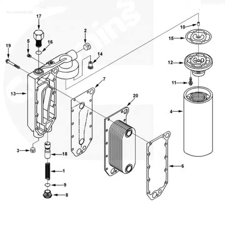
Cummins 8.3 fuel pump diagram. The following parts are suggested spares are for the Cummins 6BTA-F Item Quantity Per Service Interval Cummins PN# Fleetguard PN# 6BTA5.9-F ... Fuel Pump Datataplate to be applied to the fuel pump side of the instrument panel. ... Lock 8 3/8 inch 3 108707 Screw, Hexagon Head Cap 8 3/8 - 16 x 1 1/2 inch ... Cummins Marine QSC 8.3 Engine Diagram. Heat exchanger. Engine coolant to heat exchanger. Coolant fill cap. Expansion tank. Intake air inlet from aftercooler. Timing case cover. Sea water pump discharge. Engine mounting bracket. Fuel System Troubleshooting And Repair ... Note: All coding used in the 8.3 Liter and 9 Liter engine manuals are Cummins engine codes. ... Wiring Diagram . Source: sbmar.com. Size: 456.30 KB. Dimension: 1474 x 958. DOWNLOAD. Wiring Diagram Sheets Detail: Name: 8.3 cummins fuel shutoff solenoid wiring diagram – cranking the engine thru the magnetic switch that also operates the Bendix on the starter — draws about 50 AMPS and I call it the “suck in” circuit. File Type: JPG.
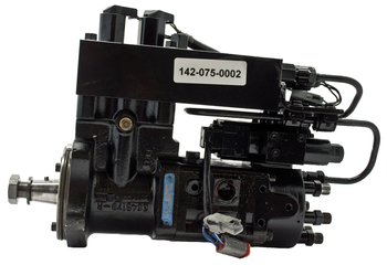
Cummins PT Fuel Pump Diagnostic . No Start, with no smoke . 1. This could be caused by the fuel pump not turning or a seized gear pump. Remove the fuel supply hose and the fuel inlet fitting from the gear pump. Check the gear pump while cranking the engine. The gear pump gears must turn. 2. If the gear pump gears do not turn, remove the fuel ... Diagram shows the 2 separate "pump" areas in the single unit, the plumbing runs to in the CAPS II pump; ie one IN/OUT (7, 9 in diagram), (This is the Gear pump) which is also before the secondary filter and one IN to the high pressure pump unit at the end of the fuel loop (11 in diagram), after secondary filter. Cummins 8.3 fuel pump diagram. Cummins 83 caps fuel system duration. Rv technical help. Engine identification engine diagrams. The friendliest place on the web for anyone with an rv or an interest in rving. Cummins celect ism isx qsm qsx engine wiring diagram. Cummins 8.3 fuel over flow/ check valve? Thread starter Floridianson; Start date Dec 22, ... There should also be a return line off of the injection pump. I had the same problem on a p7100 injection pump which is alot like the ones found on the 6cta motors. All you have to do to verify the overflow valve is good or not is pinch the rubber line ...
26 Apr 2020 — (A visual inspection of the passenger side of the engine (Google diagrams of your era's engines, and they should point to the Lift Pump.) ... Cummins Engine Company, Inc. reserves the right to make changes at any ... System Diagrams . ... The Cummins part number for the fuel injection pump.115 pages Fuel System Naturally Aspirated I Turbocharged Maximum Allowable Restriction to the Fuel Transfer Pump 75 mm Hg or Filter Head Must Not Exceed 13 in Hol Maximum Allowable Return Line Restriction Must Not Exceed 190.5 mm Hg [7.5 in Hg] Inlet Pressure to the Injection Pump Range 0.00 kPa [0.00 psi] to 39.0 kPa [5.00 psi]
Cooling System Venta De Plantas Plantas Cummins

Amazon Com Replacement 12v Fuel Shut Off Solenoid 3 For 5 9l Or 8 3l Cummins Diesel Engine 3935649 Automotive

Cummins Engine Fuel Flow Of Qsc L Youtube
How To Turn Up Your P Pump

Automotive Timing Pin And Oring Fit For Cummins Diesel 3 9 5 9l 8 3l New Us Greatrace Com
Monaco Diplomat Fuel Flow 2004 Isc 8 3l 330hp Engines Fmca Rv Forums A Community Of Rvers
1

Lot Of 2ea Cummins Bracket Wiring Retainer For Fuel Pump P N 3965124 8 3l Isc Ebay

How To Get More Power From Your P Pump Cummins Drivingline

Understanding Marine Fuel Coolers Marine Diesel Engine Cummins Diesel Engine
Dongfeng Suku Cadang Mesin 6ct8 3 3945967 Regulator Prs Plunger Buy Dcec 6ct Mesin Diesel Plunger Tekanan Minyak Regulator 3945967 Plunger Prs Regulator 3945967 Untuk 6ct Kapal Mesin Dongfeng Mesin Truk Plunger 6c 3945967

Kysor Blue Bird 2009 2013 Re 8 3 8 9l Cummins Kit 3720022 By Kysor 3720022

Ram Chrysler Oem 15 16 Promaster City Fuel Pump 68268800aa Walmart Com

Cummins Isl Isc Fuel Pumps Code 559 Spn 157 Youtube

Cummins Isc Isl Qsl High Pressure Fuel Pump Part Tx4076442rm

2002 Cummins 6ct 8 3 Air Compressor For Sale Felda Fl 202271 Mylittlesalesman Com

Reman Injection Pump Jr4076442 Case Avspare Com

Cummins 6cta8 3 G2 So20682 Parts Catalogue

Spn 1347 Fmi 3 Fault Code 272 Blog Teknisi

Dodge Chrysler Oem 05 07 Dakota 4 7l V8 Fuel System Line 68043248aa Walmart Com
Cummins Isc 8 3 L Not Starting Lift Pump Issue Irv2 Forums
2003 Cummins Isc 350hp Caps Fuel Pump Failure Fault Codes 277 539 111 Winnebago Owners Online Community

Dodge Cummins 12v Lift Pump Install Tips Overview 6bt Youtube
Cummins Isc 8 3 Stalls And Heals Overnight Fuel Pump Ecm Page 6 Irv2 Forums
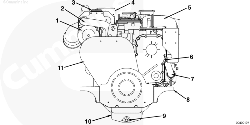
Cummins Marine Qsc 8 3 Engine Diagram Seaboard Marine
2003 Cummins Isc 350hp Caps Fuel Pump Failure Fault Codes 277 539 111 Winnebago Owners Online Community

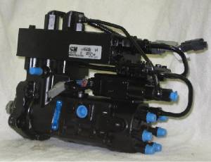
Cummins Engine Actuator Installation In An Efc Fuel Pump Housing
1

Bosch P7100 Fuel Pump Information Big Bear Engine Company
Cummins Isc 8 3 Caps Possible Alternative To Fass Upgrade Irv2 Forums
Ag Industrial Case Ih Tractors Stx325
2

Bosch P7100 Fuel Pump Information Big Bear Engine Company

Cummins Marine Qsc 8 3 Engine Diagram Seaboard Marine
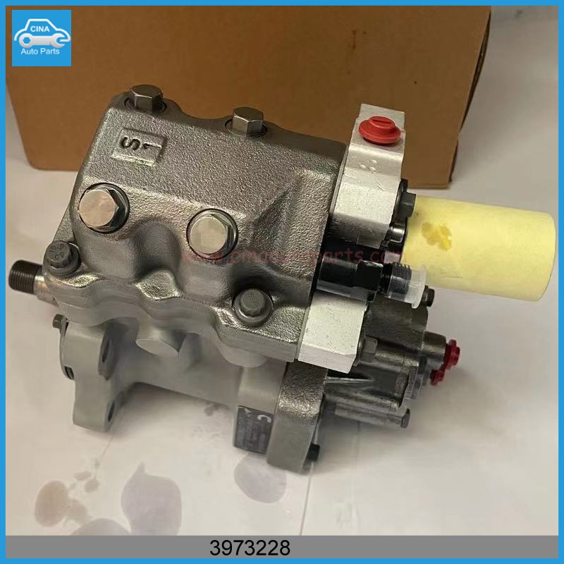
Cummins Holdwell Fuel Pump 3973228 4921431 Compatible With Engine L8 9 G8 3 6c8 3 Qsc8 3 Cm554

I Need To Know If These 2 Pumps For A 8 3 Isc Cummins Are Interchangable The Partnumber I Have Is 4076441rx The One I Am

Instructions Trouble Shooting Dieseltuff
0 Response to "37 cummins 8.3 fuel pump diagram"
Post a Comment